US809793A - Electrostatic voltmeter. - Google Patents
Electrostatic voltmeter. Download PDFInfo
- Publication number
- US809793A US809793A US20060304A US1904200603A US809793A US 809793 A US809793 A US 809793A US 20060304 A US20060304 A US 20060304A US 1904200603 A US1904200603 A US 1904200603A US 809793 A US809793 A US 809793A
- Authority
- US
- United States
- Prior art keywords
- vanes
- movable system
- case
- cells
- instrument
- Prior art date
- Legal status (The legal status is an assumption and is not a legal conclusion. Google has not performed a legal analysis and makes no representation as to the accuracy of the status listed.)
- Expired - Lifetime
Links
- 239000004020 conductor Substances 0.000 description 7
- 239000011248 coating agent Substances 0.000 description 6
- 238000000576 coating method Methods 0.000 description 6
- 239000011810 insulating material Substances 0.000 description 4
- ATJFFYVFTNAWJD-UHFFFAOYSA-N Tin Chemical compound [Sn] ATJFFYVFTNAWJD-UHFFFAOYSA-N 0.000 description 2
- 238000010276 construction Methods 0.000 description 2
- 238000000034 method Methods 0.000 description 2
- 229910001369 Brass Inorganic materials 0.000 description 1
- 229910000906 Bronze Inorganic materials 0.000 description 1
- 229910045601 alloy Inorganic materials 0.000 description 1
- 239000000956 alloy Substances 0.000 description 1
- 239000005030 aluminium foil Substances 0.000 description 1
- 239000010951 brass Substances 0.000 description 1
- 239000010974 bronze Substances 0.000 description 1
- KUNSUQLRTQLHQQ-UHFFFAOYSA-N copper tin Chemical compound [Cu].[Sn] KUNSUQLRTQLHQQ-UHFFFAOYSA-N 0.000 description 1
- 230000000694 effects Effects 0.000 description 1
- 238000009413 insulation Methods 0.000 description 1
- 229910052741 iridium Inorganic materials 0.000 description 1
- 230000001846 repelling effect Effects 0.000 description 1
- 239000000725 suspension Substances 0.000 description 1
Images

Classifications
-
- G—PHYSICS
- G01—MEASURING; TESTING
- G01R—MEASURING ELECTRIC VARIABLES; MEASURING MAGNETIC VARIABLES
- G01R5/00—Instruments for converting a single current or a single voltage into a mechanical displacement
- G01R5/28—Electrostatic instruments
Definitions
- nnrrnn s ra r ns ra -ram onrion JAMES FERGUSON, OF GLASGOW, SCOTLAND, ASSIGNOR TO KELVIN & JAMES WHITE, LIMITED, OF GLASGOW, SCOTLAND.
- This invention relates to improvements in voltmeters of the electrostatic type, and specially those with multicellular system.
- the main object of my invention is to obtain a longer and more open scale without increasing the size of the instrument to any appreciable extent.
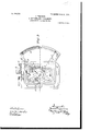
- Figure 1 is a part elevation and part vertical section of an electrostatic voltmeter embodying my invention.
- Fig. 2 is a sectional side elevation, and
- Fig. 3 is. a part horizontal section and part plan, of the same.
- the vanesF are made from exceedingly thin aluminium-foil and are ribbed, as seen in Fig. 1, to obtain the necessary rigidity.
- each vaneF an eyelet f, of brass or other easily-soldered alloy, is clenched or riv- To the eted.
- the hole in said eyelet f is of a size to fit a hard-drawn wire of one-half to one millimeter diameter, which forms the spindle of the movable system, as indicated by the letter g.
- the vanes F are properly spaced on the said spindle g by placing them in an accurately-constructed gage. After passing the spindle 9 through the said vanes F the eyelets. f are soldered to the spindle 0 while in the gage.
- the movable system is suspended with a fine wire strip It of platino-iridium or bronze. If from any cause a spark should pass between the cells C and vanes F, the suspension will act as a fuse, but as soon as fused will allow the movable system to drop.
- the whole of the fixed and movable systems is carried on a frame K, attached to a vulcanite base L and quite independent of the case M of the instrument.
- the case M has no electrical connection to either the fixed or movable systems.
- I coat the whole of the inside of the case with insulating material, and to this is attached a coating of tin-foil or other conducting material m.
- the lining or screen of conducting material m does not come quite close to the edge of the insulating-lining, thus allowing ample insnlation between the conducting material and the case aforesaid.
- This inner lining 7/7, as well as the scale-plate G, which is also insulated from the case M, is in electrical connection with the movable system.
- a geometrical fitting N between the case of the instrument and a bracket O.
- Said bracket has a rim O passing round the body of the case and provided, further, with leveling-screws P and P and a center hole Q, formed in said bracket.
- the leveling-screws P and P support the instrument, P engaging with a plane 9 and R with a slot R, While the pin it rests 5 in the small hole Q in the bracket.
- S is a revolving contact-piece for connect- IO ing either of the terminals S and S".
- T is a screw for locking the movable system for the purpose of transit.
Landscapes
- Physics & Mathematics (AREA)
- General Physics & Mathematics (AREA)
- Adjustable Resistors (AREA)
- Elimination Of Static Electricity (AREA)
Description
N0. 809,79.3;-- PATBNTED JAN. 9, 1906. J.' FERGUSON.
ELECTROSTATIC VOLTMBTBR.
APPLICATION FILED mums, 1904.
w 2 Sa -SHEET 1. Q s
g 55 "F l PATENTED JAN. 9, 1906.
J.' FERGUSON. EGTROSTATIG VOLTMBTER. APPLICATION FILED MAR.29, 1904.
2 SHEETS-SHEET 2.
"nnrrnn s ra r ns ra -ram: onrion JAMES FERGUSON, OF GLASGOW, SCOTLAND, ASSIGNOR TO KELVIN & JAMES WHITE, LIMITED, OF GLASGOW, SCOTLAND.
ELECTROSTATIC VOLTMETER.
Specification of Letters Patent.
Patented Jan. 9, 1906.
Application filed March 29, 1904. Serial No- 200,603.
To all whom it may concern:
Be it known that I, J AMES FERGUSON, electrical engineer, residing at 18 Cambridge street, in the city of Glasgow, Scotland, have invented certain new and useful Improvements in Electrostatic Voltmeters, of which the following is a specification.
This invention relates to improvements in voltmeters of the electrostatic type, and specially those with multicellular system.
The main object of my invention is to obtain a longer and more open scale without increasing the size of the instrument to any appreciable extent.
In order that my invention may be properly understood and readily carried into effect, I have hereunto appended two sheets of drawings, of which Figure 1 is a part elevation and part vertical section of an electrostatic voltmeter embodying my invention. Fig. 2 is a sectional side elevation, and Fig. 3 is. a part horizontal section and part plan, of the same.
In carrying out my invention I remove the repelling plates or screens which are fitted in the instrument hitherto constructed for the purpose of guarding the movable system against attraction by the back of the cells. As a substitute for these repelling-plates I fit narrow backs (indicated by letters A B) of vulcanite or other insulating material to the cells C. These backs A B have attached to them on the side remote from the cells C and nearest to the vanes F (comprising the movable system) when the pointer a is at zero (which position is shown in Fig. 3) a coating of tin-foil D E or other conductor narrower than the vulcanite itself to insure sufiicient insulation between it and the cells C. To keep the conductor D E at the same potential as the movable system, it is permanently in metallic connection with the movable system. It will be seen in Fig. 3 that by this arrangement considerable angular space is left free, allowing the use of cells C and vanes F of wider angle with a correspondingly greater angle of travel of the pointer a and a longer scale G without increasing the length of the said pointer.
The vanesF are made from exceedingly thin aluminium-foil and are ribbed, as seen in Fig. 1, to obtain the necessary rigidity.
center of each vaneF an eyelet f, of brass or other easily-soldered alloy, is clenched or riv- To the eted. The hole in said eyelet f is of a size to fit a hard-drawn wire of one-half to one millimeter diameter, which forms the spindle of the movable system, as indicated by the letter g. The vanes F are properly spaced on the said spindle g by placing them in an accurately-constructed gage. After passing the spindle 9 through the said vanes F the eyelets. f are soldered to the spindle 0 while in the gage. The advantage of this method of construction, reference being made to Figs. 2 and 3, is that the movable system can be constructed with the wider angle-vanes F lighter than was possible with the narrow vanes by the older method of construction.
As in the older electrostatic instruments, the movable system is suspended with a fine wire strip It of platino-iridium or bronze. If from any cause a spark should pass between the cells C and vanes F, the suspension will act as a fuse, but as soon as fused will allow the movable system to drop.
In the improved instrument short-circuiting between the movable system-namely, the vanes F and the cells O-is prevented. To efi ect this, I bush the hole I, through which the top end of the spindle g of the movable system passes, with vulcanite or other insulating material J, thus preventing connection between the movable system and its terminal.
The whole of the fixed and movable systems is carried on a frame K, attached to a vulcanite base L and quite independent of the case M of the instrument. The case M has no electrical connection to either the fixed or movable systems, To avoid error through the case M attaining a different potential to the vanes F, I coat the whole of the inside of the case with insulating material, and to this is attached a coating of tin-foil or other conducting material m. The lining or screen of conducting material m does not come quite close to the edge of the insulating-lining, thus allowing ample insnlation between the conducting material and the case aforesaid. This inner lining 7/7, as well as the scale-plate G, which is also insulated from the case M, is in electrical connection with the movable system.
To allow the instrument to be easily and accurately set up and leveled, we arrange a geometrical fitting N between the case of the instrument and a bracket O. Said bracket has a rim O passing round the body of the case and provided, further, with leveling-screws P and P and a center hole Q, formed in said bracket. The leveling-screws P and P support the instrument, P engaging with a plane 9 and R with a slot R, While the pin it rests 5 in the small hole Q in the bracket. By this arrangement the instrument when once leveled may be removed if necessary and replaced without again releveling.
S is a revolving contact-piece for connect- IO ing either of the terminals S and S".
T is a screw for locking the movable system for the purpose of transit.
I claim A voltmeter of the electrostatic type com- 5 prising a case, a coating of insulating material on the interior surface of said case, acoating of conductive material on the interior surface of said insulating-coating, a fixed system of cells within said case, a vertical back of insulatinginaterial fitted to each set of fixed 20 cells, a coating of conductive material on the exposed surface of said back, and a movable system of vanes to which the conductive coating of said backs is permanently connected.
In testimony whereof I aflix my signaturein 5 presence of two witnesses.
JAMES FERGUSON. Witnesses:
JOHN LIDDLE, AGNES MAOKINTOSH.
Priority Applications (1)
| Application Number | Priority Date | Filing Date | Title |
|---|---|---|---|
| US20060304A US809793A (en) | 1904-03-29 | 1904-03-29 | Electrostatic voltmeter. |
Applications Claiming Priority (1)
| Application Number | Priority Date | Filing Date | Title |
|---|---|---|---|
| US20060304A US809793A (en) | 1904-03-29 | 1904-03-29 | Electrostatic voltmeter. |
Publications (1)
| Publication Number | Publication Date |
|---|---|
| US809793A true US809793A (en) | 1906-01-09 |
Family
ID=2878274
Family Applications (1)
| Application Number | Title | Priority Date | Filing Date |
|---|---|---|---|
| US20060304A Expired - Lifetime US809793A (en) | 1904-03-29 | 1904-03-29 | Electrostatic voltmeter. |
Country Status (1)
| Country | Link |
|---|---|
| US (1) | US809793A (en) |
Cited By (1)
| Publication number | Priority date | Publication date | Assignee | Title |
|---|---|---|---|---|
| US2423100A (en) * | 1947-07-01 | Electrostatic |
-
1904
- 1904-03-29 US US20060304A patent/US809793A/en not_active Expired - Lifetime
Cited By (1)
| Publication number | Priority date | Publication date | Assignee | Title |
|---|---|---|---|---|
| US2423100A (en) * | 1947-07-01 | Electrostatic |
Similar Documents
| Publication | Publication Date | Title |
|---|---|---|
| US809793A (en) | Electrostatic voltmeter. | |
| US1319036A (en) | Island | |
| US762040A (en) | Electrical contact means for ship's compasses. | |
| US3110185A (en) | Split anode plasma accelerometer | |
| US500236A (en) | kennelly | |
| US496312A (en) | Electric measuring-instrument | |
| US978942A (en) | Recording-compass. | |
| US620327A (en) | Electric recording system | |
| US525020A (en) | jungner | |
| US500362A (en) | Resistance-box | |
| US1716838A (en) | Apparatus for the measurement of the level and flow of liquids | |
| US519634A (en) | Ernst kloss | |
| GB190308791A (en) | Improvements in Electrostatic Voltmeters. | |
| US571109A (en) | John p | |
| US530145A (en) | Electrometer | |
| US771968A (en) | Electrostatic instrument. | |
| US496500A (en) | Electrical measuring-instrument | |
| US1115720A (en) | Switch-key. | |
| US1361800A (en) | Voltage-protective device | |
| US1744847A (en) | Lightning arrester | |
| US435896A (en) | Electrical indicator | |
| US1915232A (en) | Multirange voltmeter-ammeter | |
| US905594A (en) | Device for locating a molten distributing-fuse. | |
| US737303A (en) | Electrical measuring instrument. | |
| US1184824A (en) | Steadying device for vertical arc-lamps. |