US809772A - Emergency-governor. - Google Patents
Emergency-governor. Download PDFInfo
- Publication number
- US809772A US809772A US1904212274A US809772A US 809772 A US809772 A US 809772A US 1904212274 A US1904212274 A US 1904212274A US 809772 A US809772 A US 809772A
- Authority
- US
- United States
- Prior art keywords
- spring
- governor
- free end
- speed
- stud
- Prior art date
- Legal status (The legal status is an assumption and is not a legal conclusion. Google has not performed a legal analysis and makes no representation as to the accuracy of the status listed.)
- Expired - Lifetime
Links
- 239000012530 fluid Substances 0.000 description 7
- 230000009471 action Effects 0.000 description 6
- 230000001105 regulatory effect Effects 0.000 description 5
- 238000013016 damping Methods 0.000 description 4
- 229910052729 chemical element Inorganic materials 0.000 description 3
- 238000010276 construction Methods 0.000 description 3
- 230000001276 controlling effect Effects 0.000 description 3
- 230000007246 mechanism Effects 0.000 description 3
- 230000008901 benefit Effects 0.000 description 2
- 230000008859 change Effects 0.000 description 2
- 230000000694 effects Effects 0.000 description 2
- 239000002184 metal Substances 0.000 description 2
- 229910000831 Steel Inorganic materials 0.000 description 1
- 208000027418 Wounds and injury Diseases 0.000 description 1
- 238000005452 bending Methods 0.000 description 1
- 230000006378 damage Effects 0.000 description 1
- 239000000835 fiber Substances 0.000 description 1
- 230000005484 gravity Effects 0.000 description 1
- 208000014674 injury Diseases 0.000 description 1
- 230000010358 mechanical oscillation Effects 0.000 description 1
- 230000000452 restraining effect Effects 0.000 description 1
- 239000010959 steel Substances 0.000 description 1
Images
Classifications
-
- F—MECHANICAL ENGINEERING; LIGHTING; HEATING; WEAPONS; BLASTING
- F01—MACHINES OR ENGINES IN GENERAL; ENGINE PLANTS IN GENERAL; STEAM ENGINES
- F01D—NON-POSITIVE DISPLACEMENT MACHINES OR ENGINES, e.g. STEAM TURBINES
- F01D21/00—Shutting-down of machines or engines, e.g. in emergency; Regulating, controlling, or safety means not otherwise provided for
- F01D21/16—Trip gear
-
- Y—GENERAL TAGGING OF NEW TECHNOLOGICAL DEVELOPMENTS; GENERAL TAGGING OF CROSS-SECTIONAL TECHNOLOGIES SPANNING OVER SEVERAL SECTIONS OF THE IPC; TECHNICAL SUBJECTS COVERED BY FORMER USPC CROSS-REFERENCE ART COLLECTIONS [XRACs] AND DIGESTS
- Y10—TECHNICAL SUBJECTS COVERED BY FORMER USPC
- Y10T—TECHNICAL SUBJECTS COVERED BY FORMER US CLASSIFICATION
- Y10T137/00—Fluid handling
- Y10T137/0971—Speed responsive valve control
- Y10T137/108—Centrifugal mass type [exclusive of liquid]
- Y10T137/1153—Excess speed responsive
-
- Y—GENERAL TAGGING OF NEW TECHNOLOGICAL DEVELOPMENTS; GENERAL TAGGING OF CROSS-SECTIONAL TECHNOLOGIES SPANNING OVER SEVERAL SECTIONS OF THE IPC; TECHNICAL SUBJECTS COVERED BY FORMER USPC CROSS-REFERENCE ART COLLECTIONS [XRACs] AND DIGESTS
- Y10—TECHNICAL SUBJECTS COVERED BY FORMER USPC
- Y10T—TECHNICAL SUBJECTS COVERED BY FORMER US CLASSIFICATION
- Y10T74/00—Machine element or mechanism
- Y10T74/11—Tripping mechanism
- Y10T74/111—Speed controlled
Definitions
- the present invention relates to emergency-governors suitable for elastic-fluid turbines and other machinery having one or more rotating parts, and has for its object to provide a governor that is simple in construction and which can be relied upon to operate each time a predetermined change in speed takes place, and this without injury to the governor itself or to the parts controlled thereby.
- each spring In carrying out the invention one or more flat springs are provided, which are mounted upon a revolving part of the turbine or other machine.
- each spring In order to obtain the required degree of flexibility, each spring must have considerable length, and since it is impracticable to use a straight or relatively straight spring on account of the great fiber stress to which it would be subjected and also because of the amount of space required the spring is coiled in the general form of a clock-spring.
- the spring resembles those commonly known by that name; but it also possesses certain characteristics peculiar to itself which will be more fully set forth later.
- the spring is given a certain initial tension which should be great enough to prevent the free end from operating until the predetermined change in speed has been attained.
- the free end of the spring can be weighted or not, as best suits the conditions. For speeds around four thousand revolutions per minute it has not been found necessary to use a weight, since the centrifugal force due to the weight of the spring itself is sufficient to produce the required deflection.
- the springs are preferably made of some homogeneous metal, such as rolled steel, and are suitably tempered.
- the shape of the spring is also an important consideration.
- the springs can either be of the opening or closing typethat is to say, they may either wind or unwind under the action of the rotating member to which they are attached.
- a device which acts directly or indirectly to effect a new condition of operation.
- an elastic-fluid turbine it may open or close a circuit or permit or cause a valve to shut and cut off the supply of motive fluid to the machine, or both. In other words, it may be used to perform any desired work.
- the outward movement ICO of the striking-arm when adjusted to underisochronism is a function of the speed alone the mechanical oscillations set up in the spring due to its striking a resistant body, such as the tripping device, caused the spring to reach outward to a position such that on striking the said device a number of times in succession the blow was sufficient to break the spring, this striking continuing even after the tripping device had receded from its normal position.
- a damping device is employed which may partake of the nature of a ring surrounding the orbit of the striking or free end of the spring.
- the ring has a small opening to receive the end of the tripping device, which opening is so arranged that after the device is actuated it will move out of the path of the arm. In this manner the dampg ing device presents a smooth unbroken sur face to the spring-arm and all tendency for V the spring to reach is obviated.
- governors maybe arranged for isochronous or under or over isochronous operation, as desired.
- the one illustrated is intended for under-isochronous operation, and the parts are commonly set to operate on a seven-per-cent. increase in speed; but the invention is not to be construed as being limited thereto.
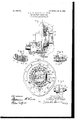
- Figure 1 is a partial view of a turbine, showing speed and emergency governors, together with a valve for shutting off the supply of steam or other elastic fluid.
- Fig. 2 is a partial view, in front elevation, taken on line 2 2 of Fig. 2 and looking in the direction of the arrow.
- Fig. 3 is a detailed view of a clock-spring emergency-governor.
- Fig. 4 is a detailed view of the means employed to secure the emergency-governor in place, the said figure being a section taken on line 4 4 of Fig. 3 and Fig. 5 is a detail View.
- 1 represents the casing of a turbine, and 2 a head, which is detachably secured thereto by bolts and incloses the speed-governor 3.
- a passage 4 which conveys steam or other elastic fluid to the nozzle and wheel-buckets. Fluid is admitted to the passage by a pipe or conduit 5.
- a flap-valve 6 Between the conduit 5 and said passage is a flap-valve 6, which is adapted to be tripped under certain conditions, as will be more fully described hereinafter.
- the valve is normally held in an open position, as shown by the latch 7, which engages a projection on the hub of the valve.
- the walls of the passage 4 terminate in a seat 8 for the valve.
- the latch 7 is mounted on a rock-shaft 9, which is located in the head 2 and extends into the main turbine-casing.
- the shaft is mounted in suitable bearings at opposite ends, and a coiled spring 10 is provided, which by torsional action tends at all times to hold the latch 7 in engagement with the valve and the tripping device 11 in a position to be engaged by the emergency-governor.
- a coiled spring 10 is provided, which by torsional action tends at all times to hold the latch 7 in engagement with the valve and the tripping device 11 in a position to be engaged by the emergency-governor.
- the valve is mounted on a rock-shaft 12, which extends to a point outside of the head and is provided with a handle whereby the valve may be set. The valve may close due to gravity or the action of a spring, or both.
- Fig. 2, 13 and 14 represent the weights on the centrifugal governor, which normally controls the speed of the moving element upon which it is mounted.
- the controlling mechanism actuated by the governor is omitted but it is to be understood that suitable controlling mechanism is employed which varies the admission of motive fluid to the turbine in accordance with the demand for energy.
- the speed-responsive device will be connected to the governing mechanism of suitable character.
- a ring 15 Located within the turbine-casing and forming a support for the governor-weights is a ring 15, that is supported by posts or pillars 16 from the moving part of the turbine. Mounted upon this ring at diametrically opposite points are coiled springs 17. Each of these springs is attached to a stud 18 at its inner end, as shown in Fig. 3, and has a free outer or striking end. Each of the springs is given an initial tension and is normally held against unwinding by the stop 19. It is to be noted that at the point 20 the springturns are slightly flattened, so that they are nearer together than on the opposite side of the supporting-stud.
- the plane of movement of the springs is at right angles to the axis of the shaft, and the securing means occupy a plane parallel with the shaft.
- securing means is more fully illustrated, wherein 15 represents the supporting-ring, and 18 the stud.
- the stud is provided with a knurled shoulder 21 and a retaining-nut 22.
- One end of the stud is provided with a squared end 23, by means of which the spring may be given a definite initial tension.
- the end of the stud opposite the retaining-nut is slotted to receive the inner end of the spring, and the stock adjacent to the slot is cut away, as at 24, to afford a better support to the short bend of the spring.
- the spring is prevented from slipping off the stud by the nut 25.
- a da1nping or limiting device 26 Surrounding the springs 17 17 is a da1nping or limiting device 26, which takes the form of a ring.
- the ring is provided with projections through which pass retainingbolts for securing it to the head 2.
- the tripping device or trigger 11 By rea son of this construction when the head is moved the emergency-valve 6, the tripping device or trigger 11, and the damping device can be removed as a unit.
- the inner surface of the damping-ring is unbroken, except for the slot at the lower portion, which receives the tripping device 11.
- the portion of the damping-ring adjacent to the end of the tripping device is recessed, so that after the latter is actuated by the spring it will occupy the recess and be out of the path oi the said spring.
- Fig. 5 On the support or ring 15 is a cut or indicator, which is definitely located, as is the hole for receiving the stud 18. After the parts are assembled loosely the stud is rotated through a certain angle until the tension of the spring is correct, after which a mark or indicator 28 is made on the shoulder 21 of the stud that registers with the indicator 27. The tension on the spring is proportional to the angle through which the stud is turned. Consequently the indicators on the stud and ring may be considered as a measure of this tension.
- a governor comprising a rotating element, and a coiled spring carried thereby having a free end, and a regulator acted upon by the spring.
- a governor comprising a rotating ele ment, and a coiled spring carried thereby having a free end, which end increases its distance from the axis of rotation under predetermined changes in speed.
- a governor comprising a rotating element, and a coiled spring mounted thereon having a free end whose axis is parallel with that of the rotating element.
- a governor comprising a rotatingelement, and a flat coiled spring mounted there on having its inner end fastened to the said element with its outer end free to move in a plane at right angles to the plane of the rotating element.
- a governor comprising a rotating element, a coiled spring mounted thereon having a free end, aregulator acted upon by the spring, and a means for preventing excess movement of the said free end.
- a governor comprising a rotating element, a coiled spring mounted thereon having a free end, and a damping device which surrounds the orbit of said free end.
- a governor comprising a rotating element, a coiled spring mounted thereon having a free end, a damping device which surrounds the orbit of said free end, and a support for the damper.
- a governor comprising a revolving element, a clock-spring carried thereby which has flattened turns and a free end, and a regulating device acted upon by the free end of the spring.
- a governor comprising a revolving element, a coiled spring having flattened turns and free end, and a means for securing the spring to the revolving element in such a position that the free end moves in a plane at right angles to that of the element.
- a governor comprising a revolving element, a coiled spring mounted thereon and having a free end, and a device which is located within the orbit of said free end and is engaged thereby when the speed of said element exceeds a certain amount.
- a governor comprising a revolving ele ment, a coiled spring mounted thereon and having a free end, a device which is located within the orbit of said free end and is engaged thereby when the speed of said element exceeds a certain amount, and a damper for preventing excess movement of the end of said spring.
- a governor comprising a rotating ele ment, a coiled spring mounted thereon having a free end, which tends to wind up or close under conditions of increasing speed, a stationary damper surrounding the orbit of said free end, and a device which extends through the damper into the path of the free end.
- a governor comprising a rotating element, a coiled spring mounted thereon having afree end, a regulating device acted upon by the spring, and a counterbalance for said spring.
- a governor comprising a rotating element, a coiled spring mounted thereon having a free end, a second spring of similar characteristic arranged to balance the first, and a regulator acted upon by the springs.
- a governor comprising a rotating element, a coiled spring mounted thereon having a free end, a valve, and a means acted upon by the free end of the spring for con trolling the valve.
- a governor comprising a rotating element, a coiled spring mounted thereon, and which has a free end that tends to wind up when rotated above a certain speed, and a means for attaching the spring to the element so that its plane of operation is at right angles to that of the element.
- a governor the combination of a support, a flat spring mounted thereon, a stud for supporting the spring under an 'initial tension, and means for indicating the proper position of the stud with respect to the support.
- a governor the combination of a support, a flat coiled spring, a stud carried by the support and arranged to impart initial movement to the spring and also to form its sole support, and an indicator for showing the correct angular position of the stud on the support.
- a governor the combination of a ring or support, a device mounted thereon which is normally restrained and operates under emergency conditions, an adjustable means for clamping the device to the ring or support, and an indicator which is a measure of the restraining force opposing the action of said device.
- a governor comprising a revolving element, a spring carried thereby which is bent in the form of a curve and is provided with a free end, and a regulating device which is acted upon by the free end of the spring under definite speed conditions.
- a governor comprising a revolving element, a spring which is bent in the form of a curve and is secured to the revolving element and has an end that is free to move toward and away from the axis -of rotation as the speed changes, and a regulating device which is caused to assume a given position by reason of the action of the free end of the spring upon a definite increase in speed.
- a governor comprising a revolving element, a spring carried thereby which is bent in the form of a curve and has a free end that moves toward and away from the axis of rotation as the speed of said element changes, a damper for preventing overtravel of the free end of the spring, and a regulating device which is acted upon by the free end of the spring before it engages the damper.
- a governor comprising a revolving element, a spring carried thereby which is secured to the element and has a free end that moves toward and away from the axis of rotation as the speed of the element changes, a damper surrounding the orbit of the free end of the spring which has an opening therein through which the free end of the spring acts, and a regulator which is under the control of the free end of the spring.
- a governor comprising a revolving element, a coiled spring carried thereby which is fixed at one point and has a free actuating end, the turns of the spring being initially flattened so that the turns will center themselves about the point of support under normal speed conditions, a damper surrounding the orbit of the free end of the spring, and a regulator that is acted upon by the spring before its free end is restrained by the damper.
Landscapes
- Engineering & Computer Science (AREA)
- Mechanical Engineering (AREA)
- General Engineering & Computer Science (AREA)
- Control Of Water Turbines (AREA)
Description
No. 809,772. PATENTBD JANQQ, 1906. J. G. GALLAN & F. R. C. BOYD.
EMERGENCY GOVERNOR.
APPLIOATIOH FILED JUNE 13.1904.
lmvenLfors-z JohnG Cal an, F redeT-icFlC. 803d CDinesses UNITE STATES PATENT FFIOE.
JOHN G. OALLAN AND FREDERIO R. O. BOYD, OF LYNN, MASSACHUSETTS, ASSIGNORS TO GENERAL ELECTRIC COMPANY, A CORPORATION OF NEW YORK.
EMERGENCY-GOVERNOR.
Specification 0f,Letters Patent.
Patented Jan. 9, 1906.
To all whom it may concern.-
Be it known that we, JOHN G. CALLAN and FREDERIC R. C. BOYD, citizens of the United States, residing at Lynn, in the county of Essex and State of Massachusetts, have invent ed certain new and useful Improvements in Emergency-Governors for Turbines and other Motors, of which the following is a specification.
The present invention relates to emergency-governors suitable for elastic-fluid turbines and other machinery having one or more rotating parts, and has for its object to provide a governor that is simple in construction and which can be relied upon to operate each time a predetermined change in speed takes place, and this without injury to the governor itself or to the parts controlled thereby.
In carrying out the invention one or more flat springs are provided, which are mounted upon a revolving part of the turbine or other machine. In order to obtain the required degree of flexibility, each spring must have considerable length, and since it is impracticable to use a straight or relatively straight spring on account of the great fiber stress to which it would be subjected and also because of the amount of space required the spring is coiled in the general form of a clock-spring.
The term eneral form is used because in.
a broad sense, the spring resembles those commonly known by that name; but it also possesses certain characteristics peculiar to itself which will be more fully set forth later.
The spring is given a certain initial tension which should be great enough to prevent the free end from operating until the predetermined change in speed has been attained. The free end of the spring can be weighted or not, as best suits the conditions. For speeds around four thousand revolutions per minute it has not been found necessary to use a weight, since the centrifugal force due to the weight of the spring itself is sufficient to produce the required deflection.
The springs are preferably made of some homogeneous metal, such as rolled steel, and are suitably tempered. The shape of the spring is also an important consideration. The springs can either be of the opening or closing typethat is to say, they may either wind or unwind under the action of the rotating member to which they are attached.
Where a spring of the opening type is used, the free end will naturally strike a more glancing blow than where a spring of the closing type is used; but the glancing effect may be simulated by bending the end of a spring of the closing type. This type of spring also has the advantage that in opening there is a tendency to reduce friction between the turns. With the closing type of spring the friction between turns can be eliminated, however, by properly spacing them, and the greater the tension the more it is supported at its weakest pointthat is, where it is attachedto a fmed support. It also has the advantage that the outward movement while in action is dampened by the decrease in movement of the free end as it winds up.
The proper shape for a spring of the closing type, neglecting the centrifugal force due to the separate turns, is a logarithmic spiral. In order to compensate for the distortion due to centrifugal force, it has been found desirable to flatten this curve 011 the side farthest from the axis of rotation to such an extent that when the carrier is rotating at normal speed the spring approximates a true logarithmic spiral. Owing to the fact that the spring is under an initial tension, the flattened portion of the curve is shifted somewhat in a direction away from the free end. I/Vhen at rest, the turns of the spring should be nearly,
if not quite, touching on the flattened side,
and when the spring is moving at speed the turns at this flattened portion will open out. The number of turns is determined by the length requisite to give the proper relation of initial to final tension without causing a dangerous stress on the metal. Experince demonstrates that the free or striking arm of the spring should be relatively long, since it secures greater accuracy and less danger of breaking than where a short arm is employed.
Located at a suitable point with respect to the free or striking arm of the spring is a device which acts directly or indirectly to effect a new condition of operation. In the case of an elastic-fluid turbine it may open or close a circuit or permit or cause a valve to shut and cut off the supply of motive fluid to the machine, or both. In other words, it may be used to perform any desired work.
It has been found that for certain speeds say four thousand revolutions per minute,
for examplewhile the outward movement ICO of the striking-arm when adjusted to underisochronism is a function of the speed alone the mechanical oscillations set up in the spring due to its striking a resistant body, such as the tripping device, caused the spring to reach outward to a position such that on striking the said device a number of times in succession the blow was sufficient to break the spring, this striking continuing even after the tripping device had receded from its normal position. In order to obviate this objection, a damping device is employed which may partake of the nature of a ring surrounding the orbit of the striking or free end of the spring. The ring has a small opening to receive the end of the tripping device, which opening is so arranged that after the device is actuated it will move out of the path of the arm. In this manner the dampg ing device presents a smooth unbroken sur face to the spring-arm and all tendency for V the spring to reach is obviated.
These governors maybe arranged for isochronous or under or over isochronous operation, as desired. The one illustrated is intended for under-isochronous operation, and the parts are commonly set to operate on a seven-per-cent. increase in speed; but the invention is not to be construed as being limited thereto.
In the accompanying drawings, which illustrate one embodiment of our invention, Figure 1 is a partial view of a turbine, showing speed and emergency governors, together with a valve for shutting off the supply of steam or other elastic fluid. Fig. 2 is a partial view, in front elevation, taken on line 2 2 of Fig. 2 and looking in the direction of the arrow. Fig. 3 is a detailed view of a clock-spring emergency-governor. Fig. 4 is a detailed view of the means employed to secure the emergency-governor in place, the said figure being a section taken on line 4 4 of Fig. 3 and Fig. 5 is a detail View.
In the drawings, 1 represents the casing of a turbine, and 2 a head, which is detachably secured thereto by bolts and incloses the speed-governor 3. In the head is provided a passage 4, which conveys steam or other elastic fluid to the nozzle and wheel-buckets. Fluid is admitted to the passage by a pipe or conduit 5. Between the conduit 5 and said passage is a flap-valve 6, which is adapted to be tripped under certain conditions, as will be more fully described hereinafter. The valve is normally held in an open position, as shown by the latch 7, which engages a projection on the hub of the valve. The walls of the passage 4 terminate in a seat 8 for the valve. The latch 7 is mounted on a rock-shaft 9, which is located in the head 2 and extends into the main turbine-casing. The shaft is mounted in suitable bearings at opposite ends, and a coiled spring 10 is provided, which by torsional action tends at all times to hold the latch 7 in engagement with the valve and the tripping device 11 in a position to be engaged by the emergency-governor. As soon as the latch is tripped the torsional spring 10 tends to return the parts to the position shown. The valve is mounted on a rock-shaft 12, which extends to a point outside of the head and is provided with a handle whereby the valve may be set. The valve may close due to gravity or the action of a spring, or both.
Referring now to Fig. 2, 13 and 14 represent the weights on the centrifugal governor, which normally controls the speed of the moving element upon which it is mounted. For simplicity of illustration the controlling mechanism actuated by the governor is omitted but it is to be understood that suitable controlling mechanism is employed which varies the admission of motive fluid to the turbine in accordance with the demand for energy. When the invention is employed in connection with motors requiring a different form of energy, the speed-responsive device will be connected to the governing mechanism of suitable character.
Located within the turbine-casing and forming a support for the governor-weights is a ring 15, that is supported by posts or pillars 16 from the moving part of the turbine. Mounted upon this ring at diametrically opposite points are coiled springs 17. Each of these springs is attached to a stud 18 at its inner end, as shown in Fig. 3, and has a free outer or striking end. Each of the springs is given an initial tension and is normally held against unwinding by the stop 19. It is to be noted that at the point 20 the springturns are slightly flattened, so that they are nearer together than on the opposite side of the supporting-stud. It is also to be noted that the point where the turns of the spring approach the closest is the point below-the horizontal line pasing through the center of the stud. By reason of this arrangement the spring will when running at its normal speed adjust itself, so that the turns are suitably spaced apart.
stantially the same initial tension; but under certain conditions it may be desirable to give them different initial tensions and place them slightly out of alinement, so that the orbit of one spring does not coincide with that of the other. With this arrangement it is possible to obtain successive operation of the triggers or other devices actuated thereby. As shown, the plane of movement of the springs is at right angles to the axis of the shaft, and the securing means occupy a plane parallel with the shaft. When two springs are provided, one acts as a counterbalance for the other.
These springs would ordinarilybe adjusted so asto have the same or sub- When only one spring is employed, a suitable counterweight should be provided.
In Fig. 4 the securing means is more fully illustrated, wherein 15 represents the supporting-ring, and 18 the stud. The stud is provided with a knurled shoulder 21 and a retaining-nut 22. One end of the stud is provided with a squared end 23, by means of which the spring may be given a definite initial tension. The end of the stud opposite the retaining-nut is slotted to receive the inner end of the spring, and the stock adjacent to the slot is cut away, as at 24, to afford a better support to the short bend of the spring. The spring is prevented from slipping off the stud by the nut 25.
Surrounding the springs 17 17 is a da1nping or limiting device 26, which takes the form of a ring. The ring is provided with projections through which pass retainingbolts for securing it to the head 2. By rea son of this construction when the head is moved the emergency-valve 6, the tripping device or trigger 11, and the damping device can be removed as a unit. The inner surface of the damping-ring is unbroken, except for the slot at the lower portion, which receives the tripping device 11. The portion of the damping-ring adjacent to the end of the tripping device is recessed, so that after the latter is actuated by the spring it will occupy the recess and be out of the path oi the said spring.
It is desirable to make the emergency de vices interchangeable, so that they may be renewed without returning the governor to the factory or without making it necessary to test each device on the particular governor to which it is to be applied. To carry out this feature of our invention, the construction shown in Fig. 5 is employed. On the support or ring 15 is a cut or indicator, which is definitely located, as is the hole for receiving the stud 18. After the parts are assembled loosely the stud is rotated through a certain angle until the tension of the spring is correct, after which a mark or indicator 28 is made on the shoulder 21 of the stud that registers with the indicator 27. The tension on the spring is proportional to the angle through which the stud is turned. Consequently the indicators on the stud and ring may be considered as a measure of this tension. In practice the emergency-springs are tested in quantities on a suitable standard gov ernor, and when the tension is correct the studs are marked at apoint-opposite the indicator 27 on the standard. The studs and springs can then be sent out as supply parts or changed from one machine to another at will, the proper setting being. determined solely by the location of the indicator. Obviously, this arrangement has great practical and commercial value.
In accordance with the provisions of the patentstatutes we have described the principle of operation of our invention, together paratus shown is only illustrative and that the invention can be carried out by other means.
What we claim as new, and desire to secure by Letters Patent of the United States, is
1. A governor comprising a rotating element, and a coiled spring carried thereby having a free end, and a regulator acted upon by the spring.
2. A governor comprising a rotating ele ment, and a coiled spring carried thereby having a free end, which end increases its distance from the axis of rotation under predetermined changes in speed.
a 3. A governor comprising a rotating element, and a coiled spring mounted thereon having a free end whose axis is parallel with that of the rotating element.
4. A governor comprising a rotatingelement, and a flat coiled spring mounted there on having its inner end fastened to the said element with its outer end free to move in a plane at right angles to the plane of the rotating element.
5. A governor comprising a rotating element, a coiled spring mounted thereon having a free end, aregulator acted upon by the spring, and a means for preventing excess movement of the said free end.
6. A governor comprising a rotating element, a coiled spring mounted thereon having a free end, and a damping device which surrounds the orbit of said free end.
7. A governor comprising a rotating element, a coiled spring mounted thereon having a free end, a damping device which surrounds the orbit of said free end, and a support for the damper.
8. A governor comprising a revolving element, a clock-spring carried thereby which has flattened turns and a free end, and a regulating device acted upon by the free end of the spring.
9. A governor comprising a revolving element, a coiled spring having flattened turns and free end, and a means for securing the spring to the revolving element in such a position that the free end moves in a plane at right angles to that of the element.
10. A governor comprising a revolving element, a coiled spring mounted thereon and having a free end, and a device which is located within the orbit of said free end and is engaged thereby when the speed of said element exceeds a certain amount.
11. A governor comprising a revolving ele ment, a coiled spring mounted thereon and having a free end, a device which is located within the orbit of said free end and is engaged thereby when the speed of said element exceeds a certain amount, and a damper for preventing excess movement of the end of said spring.
12. A governor comprising a rotating ele ment, a coiled spring mounted thereon having a free end, which tends to wind up or close under conditions of increasing speed, a stationary damper surrounding the orbit of said free end, and a device which extends through the damper into the path of the free end.
13. A governor comprising a rotating element, a coiled spring mounted thereon having afree end, a regulating device acted upon by the spring, and a counterbalance for said spring.
14. A governor comprising a rotating element, a coiled spring mounted thereon having a free end, a second spring of similar characteristic arranged to balance the first, and a regulator acted upon by the springs.
15. A governor comprising a rotating element, a coiled spring mounted thereon having a free end, a valve, and a means acted upon by the free end of the spring for con trolling the valve.
16. A governor comprising a rotating element, a coiled spring mounted thereon, and which has a free end that tends to wind up when rotated above a certain speed, and a means for attaching the spring to the element so that its plane of operation is at right angles to that of the element.
17. In a governor, the combination of a support, a flat spring mounted thereon, a stud for supporting the spring under an 'initial tension, and means for indicating the proper position of the stud with respect to the support.
18. In a governor, the combination of a support, a flat coiled spring, a stud carried by the support and arranged to impart initial movement to the spring and also to form its sole support, and an indicator for showing the correct angular position of the stud on the support.
19. In a governor, the combination of a ring or support, a device mounted thereon which is normally restrained and operates under emergency conditions, an adjustable means for clamping the device to the ring or support, and an indicator which is a measure of the restraining force opposing the action of said device.
20. A governor comprising a revolving element, a spring carried thereby which is bent in the form of a curve and is provided with a free end, and a regulating device which is acted upon by the free end of the spring under definite speed conditions.
21. A governor comprising a revolving element, a spring which is bent in the form of a curve and is secured to the revolving element and has an end that is free to move toward and away from the axis -of rotation as the speed changes, and a regulating device which is caused to assume a given position by reason of the action of the free end of the spring upon a definite increase in speed.
22. A governor comprising a revolving element, a spring carried thereby which is bent in the form of a curve and has a free end that moves toward and away from the axis of rotation as the speed of said element changes, a damper for preventing overtravel of the free end of the spring, and a regulating device which is acted upon by the free end of the spring before it engages the damper.
23. A governor comprising a revolving element, a spring carried thereby which is secured to the element and has a free end that moves toward and away from the axis of rotation as the speed of the element changes, a damper surrounding the orbit of the free end of the spring which has an opening therein through which the free end of the spring acts, and a regulator which is under the control of the free end of the spring.
I 24. A governor comprising a revolving element, a coiled spring carried thereby which is fixed at one point and has a free actuating end, the turns of the spring being initially flattened so that the turns will center themselves about the point of support under normal speed conditions, a damper surrounding the orbit of the free end of the spring, and a regulator that is acted upon by the spring before its free end is restrained by the damper.
In witness whereof we have hereunto set our hands this 10th day of June, 1904.
JOHN G. CALLAN. FREDERIC R. C. BOYD. Witnesses:
DUGALD McK. McKrLLoP, JOHN J. WALKER.
Priority Applications (1)
| Application Number | Priority Date | Filing Date | Title |
|---|---|---|---|
| US1904212274 US809772A (en) | 1904-06-13 | 1904-06-13 | Emergency-governor. |
Applications Claiming Priority (1)
| Application Number | Priority Date | Filing Date | Title |
|---|---|---|---|
| US1904212274 US809772A (en) | 1904-06-13 | 1904-06-13 | Emergency-governor. |
Publications (1)
| Publication Number | Publication Date |
|---|---|
| US809772A true US809772A (en) | 1906-01-09 |
Family
ID=2878253
Family Applications (1)
| Application Number | Title | Priority Date | Filing Date |
|---|---|---|---|
| US1904212274 Expired - Lifetime US809772A (en) | 1904-06-13 | 1904-06-13 | Emergency-governor. |
Country Status (1)
| Country | Link |
|---|---|
| US (1) | US809772A (en) |
-
1904
- 1904-06-13 US US1904212274 patent/US809772A/en not_active Expired - Lifetime
Similar Documents
| Publication | Publication Date | Title |
|---|---|---|
| US809772A (en) | Emergency-governor. | |
| US1076472A (en) | Emergency-governor. | |
| US742842A (en) | Automatic governor. | |
| US749217A (en) | Ho model | |
| US88495A (en) | Improvement in steam-engine governors | |
| US1118443A (en) | Means for changing the output of centrifugal compressors. | |
| US500019A (en) | Governor for engines | |
| US805392A (en) | Speed-governor. | |
| US88496A (en) | Improvement in steaifl-engine governors | |
| US542013A (en) | Governor | |
| US294262A (en) | Striking mechanism for clocks | |
| US2917637A (en) | Frequency-regulated turbo generator | |
| US337611A (en) | George | |
| US820913A (en) | Governing mechanism for fluid-actuated motors. | |
| US386036A (en) | And theodore | |
| US1103024A (en) | Governor. | |
| US127572A (en) | Improvement in governors for steam and other engines | |
| US1013184A (en) | Governing mechanism for mixed-pressure turbines. | |
| US1162707A (en) | Speed-indicator for cream-separators. | |
| US1728042A (en) | Emergency governing mechanism for elastic-fluid turbines and the like | |
| US466488A (en) | Island | |
| US57490A (en) | Improvement in steam-engine governors | |
| US1221757A (en) | Automatic safety-stop for engines. | |
| US221296A (en) | Improvement in governors for steam-engines | |
| US1049809A (en) | Governing mechanism for mixed-pressure turbines. |