US80973A - F e a n c is a - Google Patents
F e a n c is a Download PDFInfo
- Publication number
- US80973A US80973A US80973DA US80973A US 80973 A US80973 A US 80973A US 80973D A US80973D A US 80973DA US 80973 A US80973 A US 80973A
- Authority
- US
- United States
- Prior art keywords
- ratchet
- brake
- hay
- staple
- wagon
- Prior art date
- Legal status (The legal status is an assumption and is not a legal conclusion. Google has not performed a legal analysis and makes no representation as to the accuracy of the status listed.)
- Expired - Lifetime
Links
- XEEYBQQBJWHFJM-UHFFFAOYSA-N Iron Chemical compound [Fe] XEEYBQQBJWHFJM-UHFFFAOYSA-N 0.000 description 4
- 229910052742 iron Inorganic materials 0.000 description 2
- 238000010276 construction Methods 0.000 description 1
- 229940048662 kwai Drugs 0.000 description 1
Images
Classifications
-
- G—PHYSICS
- G05—CONTROLLING; REGULATING
- G05G—CONTROL DEVICES OR SYSTEMS INSOFAR AS CHARACTERISED BY MECHANICAL FEATURES ONLY
- G05G5/00—Means for preventing, limiting or returning the movements of parts of a control mechanism, e.g. locking controlling member
- G05G5/12—Means for preventing, limiting or returning the movements of parts of a control mechanism, e.g. locking controlling member for holding members in an indefinite number of positions, e.g. by a toothed quadrant
- G05G5/20—Means for preventing, limiting or returning the movements of parts of a control mechanism, e.g. locking controlling member for holding members in an indefinite number of positions, e.g. by a toothed quadrant by locking a quadrant, rod, or the like carried by the member
- G05G5/24—Means for preventing, limiting or returning the movements of parts of a control mechanism, e.g. locking controlling member for holding members in an indefinite number of positions, e.g. by a toothed quadrant by locking a quadrant, rod, or the like carried by the member by positive interengagement, e.g. by a pawl
-
- Y—GENERAL TAGGING OF NEW TECHNOLOGICAL DEVELOPMENTS; GENERAL TAGGING OF CROSS-SECTIONAL TECHNOLOGIES SPANNING OVER SEVERAL SECTIONS OF THE IPC; TECHNICAL SUBJECTS COVERED BY FORMER USPC CROSS-REFERENCE ART COLLECTIONS [XRACs] AND DIGESTS
- Y10—TECHNICAL SUBJECTS COVERED BY FORMER USPC
- Y10T—TECHNICAL SUBJECTS COVERED BY FORMER US CLASSIFICATION
- Y10T74/00—Machine element or mechanism
- Y10T74/20—Control lever and linkage systems
- Y10T74/20576—Elements
- Y10T74/20636—Detents
- Y10T74/20714—Lever carried rack
- Y10T74/2072—Pivoted
Definitions
- Ivzvenor fwes: fw" 5W *Kwai wwweww l WM'W MI i nihtstr gatrnt @Hire Laar@ Palmi No. 80,973, @zaad August 11, 186s.
- my invention consists in providing' means by which audriver on the top of a high load of hay, barrels, or the like, may apply a wagon-brake to the wheels thereof.
- Figui-e2 of the drawings shows a plan view of a wagon and hay-rack with my'brake attached
- Letter C is the point at which the rods B .'B, are united on a bolt or key.
- Letter D is a rod extending forward from the bolt C, to which it is attached, and itis joined at its forward end to a clevis, E. This clevis E is connected at its rear end to the rod D, and .at its front end to the lower end of the-lever G, next mentioned.Y
- the lever Gr is united at the clevis E,in themanner shown, and it is also pivoted in a slot in the block II, in the manner represented in fig. 2.k It extends upward from the block H to a point s uiiiciently high to allow the top thereof to be seen abovea high load-upon they wagon, where itis attached to the forward end of the ratchet K, as hereinafter described.
- a i The block II is fastened securely' on the front cross-bar of the hay-rack, and extends forward therefrom about ten inches, more or less. The forward end ofthis block is slotted or mortised as shown, to allow space for pivoting therein the lever G, and allowing the same to work back and forth.
- the ratchet K is united to the top-of lever G, in the manner shown. It is a straight plate of iron, with a handle cut therein at its rear end, and it is toothed on the under side to providemeans for fastening the brake in such position as the operator may desire.
- the letters O O are upright posts extending upward from the main body of the hay-rack to a point a few inches above the top of leverV G ⁇ ,.where they are united by bolts or other suitable means.
- I attach an iron staple, S, and arrange it to work in conjunction with the ratchet K, in fasteniugthe brakes in any desired position, or in loosening the same from the wheels.
- That part of the staple upor which the ratchet rests is bevelled en its forward side, te allow for an easy movement of the ratchet to therear.
- the drawings show the form in which this staple is constructed, and the mode of operating the ratchet therein.
- rIhe upright posts O serve not only asa rest and support for the staple and ratchet above named, but also as a support for the front end ⁇ of the loaden the hay-rack.
- the driver To operate rny brake, the. driver on the load draws tho ratchet K to thel rear, and the rake is thereby applied. To release the brake from the wheels, the driver raises the ratchet from the bevelled part of the staple, and allows the ratchet and leverconnected therewith to be drawn forward.
- a brake for wagons adapted for operation by an operator on a high load, and having lever G block H, ratchet K, staple S, and posts O O, constructed, arranged, and operating substantially as specified'.
Landscapes
- Physics & Mathematics (AREA)
- General Physics & Mathematics (AREA)
- Engineering & Computer Science (AREA)
- Automation & Control Theory (AREA)
- Tires In General (AREA)
Description
'F. A. KINGTON.
Wagonl Brake. Nol 80,973. Patented Aug. H. 1868.
Ivzvenor: fwes: fw" 5W *Kwai wwweww l WM'W MI i nihtstr gatrnt @Hire Laar@ Palmi No. 80,973, @zaad August 11, 186s.
IMPRV WAGONLQGK.
tlge .tlgetnletiiemh tu in ipse titiers @that mit* making artt tf tige anni.
TO ALL WHOM IT MAY CONCERN:
Be it known that I, FRANCIS A. KINGTorLof Meudon, in the county of Adams, and State of Illinois, have invented a new and useful machine called a Wagon-Loek, to he used in drawing hay, grain, or any high 'loads on a wagon, such as boxes or barrels; and I do hereby declare that the followingis a full, clear, and exact description of the construction and operation of the same, reference being had to the annexed drawings, making a part of this specification, and to the letters and figures of reference marked thereon.`
The nature of my invention consists in providing' means by which audriver on the top of a high load of hay, barrels, or the like, may apply a wagon-brake to the wheels thereof. i
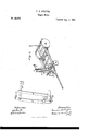
Figui-e2 of the drawings shows a plan view of a wagon and hay-rack with my'brake attached, and
Figure lis a detail view of the upright portion of my brake.`
I construct the brake proper in the usuel form, as shown-by the letters A-A and B B, the former being the levers, and the latter being the rods connected therewith, in the form and manner represented. y 1
Letter C is the point at which the rods B .'B, are united on a bolt or key. Letter D is a rod extending forward from the bolt C, to which it is attached, and itis joined at its forward end to a clevis, E. This clevis E is connected at its rear end to the rod D, and .at its front end to the lower end of the-lever G, next mentioned.Y
The lever Gr is united at the clevis E,in themanner shown, and it is also pivoted in a slot in the block II, in the manner represented in fig. 2.k It extends upward from the block H to a point s uiiiciently high to allow the top thereof to be seen abovea high load-upon they wagon, where itis attached to the forward end of the ratchet K, as hereinafter described. A i The block II is fastened securely' on the front cross-bar of the hay-rack, and extends forward therefrom about ten inches, more or less. The forward end ofthis block is slotted or mortised as shown, to allow space for pivoting therein the lever G, and allowing the same to work back and forth.
The ratchet K is united to the top-of lever G, in the manner shown. It is a straight plate of iron, with a handle cut therein at its rear end, and it is toothed on the under side to providemeans for fastening the brake in such position as the operator may desire. I l
The letters O O are upright posts extending upward from the main body of the hay-rack to a point a few inches above the top of leverV G`,.where they are united by bolts or other suitable means. On one side of these posts, near'their summits, I attach an iron staple, S, and arrange it to work in conjunction with the ratchet K, in fasteniugthe brakes in any desired position, or in loosening the same from the wheels. That part of the staple upor which the ratchet rests is bevelled en its forward side, te allow for an easy movement of the ratchet to therear. The drawings show the form in which this staple is constructed, and the mode of operating the ratchet therein.
rIhe upright posts O serve not only asa rest and support for the staple and ratchet above named, but also as a support for the front end` of the loaden the hay-rack.
To operate rny brake, the. driver on the load draws tho ratchet K to thel rear, and the rake is thereby applied. To release the brake from the wheels, the driver raises the ratchet from the bevelled part of the staple, and allows the ratchet and leverconnected therewith to be drawn forward.
What I claim as my invention, and desire to securev by Letters Patent, is
A brake for wagons, adapted for operation by an operator on a high load, and having lever G block H, ratchet K, staple S, and posts O O, constructed, arranged, and operating substantially as specified'.
FRANCIS A. KINGTON.
Witnesses:
M. R. BUrz, L. EQEMMONS.
Publications (1)
| Publication Number | Publication Date |
|---|---|
| US80973A true US80973A (en) | 1868-08-11 |
Family
ID=2150467
Family Applications (1)
| Application Number | Title | Priority Date | Filing Date |
|---|---|---|---|
| US80973D Expired - Lifetime US80973A (en) | F e a n c is a |
Country Status (1)
| Country | Link |
|---|---|
| US (1) | US80973A (en) |
-
0
- US US80973D patent/US80973A/en not_active Expired - Lifetime
Similar Documents
| Publication | Publication Date | Title |
|---|---|---|
| US80973A (en) | F e a n c is a | |
| US59610A (en) | Improvement in vehicles | |
| US93205A (en) | Improvement in wagons | |
| US87782A (en) | Improvement in horse-rakes | |
| US32231A (en) | Improvement in plows | |
| US67132A (en) | Joseph myers | |
| US62430A (en) | little field | |
| US49856A (en) | Improvement in corn-cultivators | |
| US267328A (en) | Wagon-brake | |
| US96576A (en) | Horse hay-rake | |
| US47017A (en) | Improvement in cultivators | |
| US115909A (en) | Improvement in horse hay-rakes | |
| US98355A (en) | Improvement in stump-extractors | |
| US216999A (en) | Improvement in wheelbarrows | |
| US62524A (en) | William l | |
| US584829A (en) | Hay-wagon brake | |
| US14794A (en) | Xwagon-tongue | |
| US58014A (en) | Improvement in wagon-brakes | |
| US42932A (en) | Improvement in cultivators | |
| US4775A (en) | Carbiagke-bkake | |
| US108996A (en) | Improvement in the attachment of cultivator-frames to wagon axle-trees | |
| US65700A (en) | William sloan | |
| US52731A (en) | Improvement in wagon-brakes | |
| US26472A (en) | brown | |
| US75127A (en) | Improvement in cultivators |