US809704A - Motor-plow. - Google Patents
Motor-plow. Download PDFInfo
- Publication number
- US809704A US809704A US26442205A US1905264422A US809704A US 809704 A US809704 A US 809704A US 26442205 A US26442205 A US 26442205A US 1905264422 A US1905264422 A US 1905264422A US 809704 A US809704 A US 809704A
- Authority
- US
- United States
- Prior art keywords
- wheel
- plow
- frame
- motor
- indicated
- Prior art date
- Legal status (The legal status is an assumption and is not a legal conclusion. Google has not performed a legal analysis and makes no representation as to the accuracy of the status listed.)
- Expired - Lifetime
Links
Images


Classifications
-
- B—PERFORMING OPERATIONS; TRANSPORTING
- B62—LAND VEHICLES FOR TRAVELLING OTHERWISE THAN ON RAILS
- B62K—CYCLES; CYCLE FRAMES; CYCLE STEERING DEVICES; RIDER-OPERATED TERMINAL CONTROLS SPECIALLY ADAPTED FOR CYCLES; CYCLE AXLE SUSPENSIONS; CYCLE SIDECARS, FORECARS, OR THE LIKE
- B62K5/00—Cycles with handlebars, equipped with three or more main road wheels
- B62K5/02—Tricycles
- B62K5/027—Motorcycles with three wheels
Definitions
- This invention relates to plows such as used upon farms for tilling the soil.
- the object of the invention is to produce a plow which will be advanced by a motor carried on the framework thereof.
- Special objects of the invention are to provide operating mechanism which is of simple construction and which enables the operation of the plow to be easily controlled by a person not skilled in the mechanical arts.
- the invention consists in the construction and combination of parts, to be more fully described hereinafter and definitely set forth in the claim.
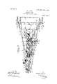
- Figure 1 is a side elevation of a plow constructed according to my invention.
- Fig. 2 is a plan.
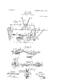
- Fig. 3 is a side elevation of the plow-beam and the contiguous parts of the plow-frame, certain parts being broken away and shown in section, as will appear. The purpose of this view is to illustrate the manner of raising and lowering the plow-beam.
- Fig. .4 is av horizontal section taken just above the plow-beam and illustrating a modified arrangement in which the beam is equipped with two plows instead of one, as in Fig. 3.
- Fig. 5 is a rear elevation of the forward axle and illustrating the details of construction.
- Fig. 6 is an end elevation of the axle shown in Fig. 5 and illustrating the mechanism for raising and lowering the furrow-wheel
- Fig. 7 is a front elevation of the plow.
- 1 represents the frame of the implement, and this frame is preferably of symmetrical form, comprising side stringers 2, which diverge forwardly, as indicated, the same being connected by transverse frame-bars Near its rear portion the frame is provided with a pair of oppositely-disposed parallel frame-bars which are disposed longitudinally of the machine, as shown, so as to present a wheel- 1 space 5 therebetwcen. ln this wheel-space a mam wheel or drivmg-wheel 6 is rotatably mounted upon a shaft 7, which shaft 1s,car
- this driving-wheel runs upon the ground and supports the rear of the frame.
- This wheel is driven by the motor in a manner which will be described hereinafter and operates to advance the entire machine.
- the surface of the wheel is preferably pro: vided with the usual ribs or teeth 8, which engage the surface of the ground as the implement advances.
- a motor 9 is provided Near the middle portion of the frame 1 .
- this motor should be a gasolene motor, as illustrated, the gasolene therefor being supplied from tanks 10, arranged forwardly thereof, as indicated.-
- the motor, well as the tanks 10, is supported upon the transverse framebars 3, as will be readily understood.
- the shaft 11 of the motor is of course a horizontal shaftfas indicated. It carries a fiy-wheel 12 with a broad face, about which a band-brake 13 is arranged, as shown.
- the details of the arrangement of this brake will be described more fully hereinafter. Sufiice it to say at this point that the brake affords means for controlling the speed of the motor.
- a sprocket-wheel 1a is mounted on the shaft 11, and over this sprocket-wheel a driving-chain 15 extends rearwardly, the rear extremity of. this chain passing around a sprocketwheel 16, carried on a counter-shaft 17. From the countershaft 17 the main wheel 6 is adapted to be driven by a main driving-chain 18. This chain passes about a main sprocket-wheel 19, which is rigidly carried by the main wheel 6, as indicated in Fig. 1.
- the driving of the main wheel 6 is controlled by means of a clutch 20, disposed near the chain 15.
- the mechanism for actuating this clutch will be described more fully hereinafter. It may be stated, however, at this point that the purpose of the clutch is to en- ITO .channel or guide-groove 37.
- the forward portion of the frame 1 is supported upon an axle 27, to the upper side of which springs 28 attach.
- These springs 28 attach to the forward corners of the frame, as indicated, and extend rearwardly, at which point they are provided with laterally-disposed necks 29, which attach to the side stringers 2, as indicated.
- the construction of the axle 27 is very clearly shown in Fig. 5. It is formed at its extremities with forks 30, which form knuckle-joints 31 with knuckles 32 and 33. These knucklejoints include vertical pivot-pins 34, which operate as axes of rotation for the knuckles in the usual manner.
- a spindle 35 projects outwardly, to which a wheel 36 at the right of the implement is attached in any suitable manner.
- the body of the knuckle 32 has the form of a vertically-elongated bar, the outer face whereof is provided with a vertical In this guidegroove 37 a slide-block 38 is mounted, and this slide-block is formed with an outwardly-projecting spindle 39, upon which the opposite wheel 40 is mounted, as indicated.
- the pur-- pose of mounting the Wheel upon this slideblock is to enable the height thereof to be readily adjusted. The mechanism for effecting this adjustment will be described more fully hereinafter.
- the knuckles 32 and 33 are provided with inwardly-projecting inclined arms 41, which extend,preferably, toward the rear, as indicated, and these arms are formed with eyes at their extremities, enabling them to be connected by a link 42, as shown most clearly in Figs. 2 and 5. the knuckles to be moved in unison, so that if one of them be moved the movement will be imparted to the other in a well-understood manner.
- I provide means for controlling the knuckle 33.
- the said knuckle is provided with an inwardly-projecting arm 43, the extremity whereof is attached to an inclined link 44, which extends rearwardly through the slots 54, as indicated.
- This link 42 enables under the frame 1, passing near its rear extremity through a guide-bracket 45, attached to the under side of the frame, as indicated most clearly in Fig. 1.
- the extremity of the link 44 is formed with teeth, so that this portion of the link constitutes a rack or rack-bar 46, the teeth of this rack meshing with a worm 47, which is attached to the extremity of an inclined shaft 48, mounted in any suitable manner in the frame, as indicated.
- the upper extremity of this shaft 48 is provided with a hand-wheel 49, which is in convenient reach from the seat 50'for the driver of the implement, the said seat being preferably located substantially over the main wheel 3.
- the link 44 may be displaced longitudinally, which will operate to rotate the knuckles 32 and 33 in either direction.
- the left-hand frame-bar 4 supports the plow-beam 51.
- the manner of supporting the plow-beam and adjusting the same will now be described, referring especially to Fig. 3.
- the extremities of the links 57 and 58 are attached to operating-levers 60 and 61, which cooperate with the segment in a well-known manner. Attention is called to the fact that these levers 60 and 61 both operate upon the same segment, the lever 60 cooperating with the rear portion of the segment, while the lever 61 cooperates with the forward portion. Thus a movement of the levers tending to separate them operates to raise the plowbeam, and the movement in the opposite direction of course operates to lower the beam.
- the plow 62 is attached to a'plowshare 63, carried on the under side of the beam, as indicated, the said plowsh'are being preferably secured in position by a diagonal brace 64, also attached to the under side of the beam.
- a colter 65 Forward of the plow 62 a colter 65 is attached, the same being carried upon a fork 66, having attached, as indicated in Fig. 2, and cooper-- ating with this segment there is a lever 70.
- This lever is for the purpose of controlling the adjustment'of the slide-block 38, referredto above.
- T c this end the link 71 is provided, which leads forwardly in an inclined direction, as shown in Fig.2.
- the forward extremity of this link attaches to a bell-crank lever 72, as indicated most clearly in Figs. 1 and 6.
- This bell-crank lever is preferably pivotedto the upper extremity of the body of the knuckle 32, and one of its arms is provided with a link 73, the lower extremity of which is pivoted to the block 38 at 7 4, as illustrated in Fig. 6. From this arrangement evidently by moving the lever 7 0 forwardly or rearwardly the position of the slide-block 38 may be adjusted so as to raise or lower the wheel 40. -1n practice the implement may be constructed so as to carry a single plow or more than one plow. In Fig. 4 I have illustrated the arrangement I adopt for mounting two plows and 76 upon the beam.
- bracket 77 the body whereof is inclined, as shown, and disposed directly beneath the beam 78, the same being attached thereto by a suitable bolt 79, as shown.
- the bracket 77 is formed at its extremities with longitudinal extensions 80, to which the plowshares 81 attach by bolts. Beyond the extensions the ends of the bracket are bent inwardly, so as to form feet 82, which are attached to the sides of the beam, as shown.
- the manner of mounting such a beam carrying two plows, as illustrated, would be the same as that described above.
- the extremities of the beam project through guide-slots 83, formed in vertically-disposed guide-bars 84.
- the driverof the implement would be located at the seat 50, in which position he would be within easy reach of the hand-wheel 49 and the handles of the'levers 60, 61', 22, 23, and 7 O.
- the lever 23 enables the clutch 20 to be thrown in and out as desired, while the lever 22 would enable the brake-band 13 to be applied at will.
- the lever 70 When it is desired to adjust the position of the forward axle, the lever 70 would be operatedso as to raise or lower the knuckle 32 in the manner just described.
- the rotation of the shaft of the motor through the mechanism described operates to rotate the main wheel 6 r and advance the implement, so that the plow 62 will throw up the earth. Attention is called to the fact that the plow 62 is located to the left of the main wheel, and it operates to throw the earth away from the wheel. In this way the main wheel will always run upon unbroken land and will have a better footing or holding power for this reason.
- the handwheel 49 affords means for steering the imple ment so as to turn the same at the end of a furrow. As described above, this wheel operates through the worm L7 to actuate the link 44, and this in turn moves the knuckles 32 and 33, thus changing the angular position of the wheels 36 and 40.
- the springs 28 at the front, which support the frame upon the axle 27 are conducive to easy riding of the frame upon its supports.
- the shaft 11 preferably projects well beyond the frame of the machine and carries a pulley 11, which enables the machine to be used as a portable engine when desired. 1
- a frame comprising forwardly-diverging side stringers and having a wheel'space formed in the rear portion thereof, a main driving-wheel rotatably mounted in said frame in said wheel-space, means for driving said wheel, springs attached to the forward extremity of said frame and having laterallydisposed necks attached to said side stringers, an axle attached to the under side of said stringers and wheels mounted upon said axle.
Landscapes
- Engineering & Computer Science (AREA)
- Mechanical Engineering (AREA)
- Soil Working Implements (AREA)
Description
PATENTED JAN. 9, 1906.
' H. J. KYLE.
MOTOR PLOW.
APPLICATION FILED JUNE 9, 1905.
4 SHEETS-SHEET l.
No. 809,704. PATENTED JAN. 9, 1906.
H. J. KYLE. MOTOR PLOW. APPLICATION FILED JUNE 9,1905.
4 SHEETS-SHEET z.
WITNESSES:
PATENTED JAN. 9, 1906.
H. J. KYLE. MOTOR PLOW. APPLICATION FILED JUNE9,1905.
4 SHEETSSHEET 3.
WITNESSES.
A a ATTORNEYS PATENTED JAN. 9, 1906.
H. J. KYLE. MOTOR PLOW.
APPLICATION FILED JUNE 9,1905.
4 SHEETS-SHEET 4.
lNVE/VTUR .f/afg .[Jfgje ATTORNEYS HENRY JERO KYLE, OF TlPTON, INDIANA.
, MOTOR=PLOW.
Specification of Letters Patent.
Patented Jan. .9, 1906.
Application filed ne 9,1905. Serial No. 26 L422.
To all whom it may concern.-
Be it known that l, HENRY Jmzo KYLE, a citizen of the United States, and a resident of Tipton, in the county of Tipton and State of Indiana, have invented a new and improved Motor-Plow, of which the following is a full, clear, and exact description.
This invention relates to plows such as used upon farms for tilling the soil.
The object of the invention is to produce a plow which will be advanced by a motor carried on the framework thereof.
Special objects of the invention are to provide operating mechanism which is of simple construction and which enables the operation of the plow to be easily controlled by a person not skilled in the mechanical arts.
The invention consists in the construction and combination of parts, to be more fully described hereinafter and definitely set forth in the claim.
Reference is to be had to the accompanying drawings, forming a part of this specification, in which similar characters of reference indicate corresponding parts in all the figures.
Figure 1 is a side elevation of a plow constructed according to my invention. Fig. 2 is a plan. Fig. 3 is a side elevation of the plow-beam and the contiguous parts of the plow-frame, certain parts being broken away and shown in section, as will appear. The purpose of this view is to illustrate the manner of raising and lowering the plow-beam. Fig. .4 is av horizontal section taken just above the plow-beam and illustrating a modified arrangement in which the beam is equipped with two plows instead of one, as in Fig. 3. Fig. 5 is a rear elevation of the forward axle and illustrating the details of construction. Fig. 6 is an end elevation of the axle shown in Fig. 5 and illustrating the mechanism for raising and lowering the furrow-wheel, and Fig. 7 is a front elevation of the plow.
Referring more particularly to the parts, 1 represents the frame of the implement, and this frame is preferably of symmetrical form, comprising side stringers 2, which diverge forwardly, as indicated, the same being connected by transverse frame-bars Near its rear portion the frame is provided with a pair of oppositely-disposed parallel frame-bars which are disposed longitudinally of the machine, as shown, so as to present a wheel- 1 space 5 therebetwcen. ln this wheel-space a mam wheel or drivmg-wheel 6 is rotatably mounted upon a shaft 7, which shaft 1s,car
ried in bearings mounted on the aforesaid frame-bars i. As indicated in Fig. 1, this driving-wheel runs upon the ground and supports the rear of the frame. This wheel is driven by the motor in a manner which will be described hereinafter and operates to advance the entire machine. For this purpose the surface of the wheel is preferably pro: vided with the usual ribs or teeth 8, which engage the surface of the ground as the implement advances.
Near the middle portion of the frame 1 a motor 9 is provided. I prefer that this motor should be a gasolene motor, as illustrated, the gasolene therefor being supplied from tanks 10, arranged forwardly thereof, as indicated.- The motor, well as the tanks 10, is supported upon the transverse framebars 3, as will be readily understood. The shaft 11 of the motor is of course a horizontal shaftfas indicated. It carries a fiy-wheel 12 with a broad face, about which a band-brake 13 is arranged, as shown. The details of the arrangement of this brake will be described more fully hereinafter. Sufiice it to say at this point that the brake affords means for controlling the speed of the motor. At a suitable point, preferably near the fly-wheel or brake-wheel 12, a sprocket-wheel 1a is mounted on the shaft 11, and over this sprocket-wheel a driving-chain 15 extends rearwardly, the rear extremity of. this chain passing around a sprocketwheel 16, carried on a counter-shaft 17. From the countershaft 17 the main wheel 6 is adapted to be driven by a main driving-chain 18. This chain passes about a main sprocket-wheel 19, which is rigidly carried by the main wheel 6, as indicated in Fig. 1.
The driving of the main wheel 6 is controlled by means of a clutch 20, disposed near the chain 15. The mechanism for actuating this clutch will be described more fully hereinafter. It may be stated, however, at this point that the purpose of the clutch is to en- ITO .channel or guide-groove 37.
pose it is attached to the extremity of the understood.
Attention is called to the fact that the two levers 22 and 23 both operate upon the same segment, being attached on opposite sides thereof. This arrangement is made possible because the range of movement of the lever 23 is upon the forward portion of the segment, while the range of movement of the lever 22 is upon the rear portion of the segment.
The forward portion of the frame 1 is supported upon an axle 27, to the upper side of which springs 28 attach. These springs 28 attach to the forward corners of the frame, as indicated, and extend rearwardly, at which point they are provided with laterally-disposed necks 29, which attach to the side stringers 2, as indicated. The construction of the axle 27 is very clearly shown in Fig. 5. It is formed at its extremities with forks 30, which form knuckle-joints 31 with knuckles 32 and 33. These knucklejoints include vertical pivot-pins 34, which operate as axes of rotation for the knuckles in the usual manner. From the side of the knuckle 33 a spindle 35 projects outwardly, to which a wheel 36 at the right of the implement is attached in any suitable manner. The body of the knuckle 32 has the form of a vertically-elongated bar, the outer face whereof is provided with a vertical In this guidegroove 37 a slide-block 38 is mounted, and this slide-block is formed with an outwardly-projecting spindle 39, upon which the opposite wheel 40 is mounted, as indicated. The pur-- pose of mounting the Wheel upon this slideblock is to enable the height thereof to be readily adjusted. The mechanism for effecting this adjustment will be described more fully hereinafter. The knuckles 32 and 33 are provided with inwardly-projecting inclined arms 41, which extend,preferably, toward the rear, as indicated, and these arms are formed with eyes at their extremities, enabling them to be connected by a link 42, as shown most clearly in Figs. 2 and 5. the knuckles to be moved in unison, so that if one of them be moved the movement will be imparted to the other in a well-understood manner.
I provide means for controlling the knuckle 33. For this purpose the said knuckle is provided with an inwardly-projecting arm 43, the extremity whereof is attached to an inclined link 44, which extends rearwardly through the slots 54, as indicated.
This link 42 enables under the frame 1, passing near its rear extremity through a guide-bracket 45, attached to the under side of the frame, as indicated most clearly in Fig. 1. To the rear of the guide-bracket 45 the extremity of the link 44 is formed with teeth, so that this portion of the link constitutes a rack or rack-bar 46, the teeth of this rack meshing with a worm 47, which is attached to the extremity of an inclined shaft 48, mounted in any suitable manner in the frame, as indicated. The upper extremity of this shaft 48 is provided with a hand-wheel 49, which is in convenient reach from the seat 50'for the driver of the implement, the said seat being preferably located substantially over the main wheel 3. Evidently by rotating the worm 47 the link 44 may be displaced longitudinally, which will operate to rotate the knuckles 32 and 33 in either direction.
The left-hand frame-bar 4, referred to above, supports the plow-beam 51. The manner of supporting the plow-beam and adjusting the same will now be described, referring especially to Fig. 3.
To the under side of the frame-bar, which is at the left, I attach downwardly-projecting guide-bars 52. These bars 52 are rigidly secured in position by diagonal braces or tiebars 53. The bodies of these tiebars are formed with slots 54, which pass through their front and rear faces and extend longitudinally throughout substantially the entire length of the bars, as indicated. In this way these bars constitute guides for the beam 51 of the plow, the extremities whereof project On the upper side of the frame-bar 4 bell-crank levers 55 are mounted in any suitable manner, the said levers having horizontal arms, which are connected by links 56 with the extremities of the beam 51, as indicated. These levers 55 have vertical arms which are connected to links 57 and 58, which extend toward a segment 59, said segment being attached to the upper side of the frame member, as shown.
The extremities of the links 57 and 58 are attached to operating-levers 60 and 61, which cooperate with the segment in a well-known manner. Attention is called to the fact that these levers 60 and 61 both operate upon the same segment, the lever 60 cooperating with the rear portion of the segment, while the lever 61 cooperates with the forward portion. Thus a movement of the levers tending to separate them operates to raise the plowbeam, and the movement in the opposite direction of course operates to lower the beam. The plow 62 is attached to a'plowshare 63, carried on the under side of the beam, as indicated, the said plowsh'are being preferably secured in position by a diagonal brace 64, also attached to the under side of the beam. Forward of the plow 62 a colter 65 is attached, the same being carried upon a fork 66, having attached, as indicated in Fig. 2, and cooper-- ating with this segment there is a lever 70. This lever is for the purpose of controlling the adjustment'of the slide-block 38, referredto above. T c this end the link 71 is provided, which leads forwardly in an inclined direction, as shown in Fig.2. The forward extremity of this link attaches to a bell-crank lever 72, as indicated most clearly in Figs. 1 and 6. This bell-crank lever is preferably pivotedto the upper extremity of the body of the knuckle 32, and one of its arms is provided with a link 73, the lower extremity of which is pivoted to the block 38 at 7 4, as illustrated in Fig. 6. From this arrangement evidently by moving the lever 7 0 forwardly or rearwardly the position of the slide-block 38 may be adjusted so as to raise or lower the wheel 40. -1n practice the implement may be constructed so as to carry a single plow or more than one plow. In Fig. 4 I have illustrated the arrangement I adopt for mounting two plows and 76 upon the beam. With this arrangement I use a bracket 77, the body whereof is inclined, as shown, and disposed directly beneath the beam 78, the same being attached thereto by a suitable bolt 79, as shown. The bracket 77 is formed at its extremities with longitudinal extensions 80, to which the plowshares 81 attach by bolts. Beyond the extensions the ends of the bracket are bent inwardly, so as to form feet 82, which are attached to the sides of the beam, as shown. The manner of mounting such a beam carrying two plows, as illustrated, would be the same as that described above. The extremities of the beam project through guide-slots 83, formed in vertically-disposed guide-bars 84.
The mode of operation of the plow should be clearly understood from the foregoing.
However, it may be said in recapitulation that the driverof the implement would be located at the seat 50, in which position he would be within easy reach of the hand-wheel 49 and the handles of the'levers 60, 61', 22, 23, and 7 O.
The lever 23 enables the clutch 20 to be thrown in and out as desired, while the lever 22 would enable the brake-band 13 to be applied at will. When it is desired to adjust the position of the forward axle, the lever 70 would be operatedso as to raise or lower the knuckle 32 in the manner just described. The rotation of the shaft of the motor through the mechanism described operates to rotate the main wheel 6 r and advance the implement, so that the plow 62 will throw up the earth. Attention is called to the fact that the plow 62 is located to the left of the main wheel, and it operates to throw the earth away from the wheel. In this way the main wheel will always run upon unbroken land and will have a better footing or holding power for this reason. The handwheel 49 affords means for steering the imple ment so as to turn the same at the end of a furrow. As described above, this wheel operates through the worm L7 to actuate the link 44, and this in turn moves the knuckles 32 and 33, thus changing the angular position of the wheels 36 and 40. The springs 28 at the front, which support the frame upon the axle 27 are conducive to easy riding of the frame upon its supports. The shaft 11 preferably projects well beyond the frame of the machine and carries a pulley 11, which enables the machine to be used as a portable engine when desired. 1
Having thus described my invention, I claim as new and desire to secure by Letters Patent- In a plow of the class described, in combination, a frame comprising forwardly-diverging side stringers and having a wheel'space formed in the rear portion thereof, a main driving-wheel rotatably mounted in said frame in said wheel-space, means for driving said wheel, springs attached to the forward extremity of said frame and having laterallydisposed necks attached to said side stringers, an axle attached to the under side of said stringers and wheels mounted upon said axle. In testimony whereof lhave signed my name to this specification in the presence of two subscribing witnesses.
HENRY J ER-O KYLE. Witnesses:
W. A. BROOKMAN,
FRANK J. Bowen.
Priority Applications (1)
| Application Number | Priority Date | Filing Date | Title |
|---|---|---|---|
| US26442205A US809704A (en) | 1905-06-09 | 1905-06-09 | Motor-plow. |
Applications Claiming Priority (1)
| Application Number | Priority Date | Filing Date | Title |
|---|---|---|---|
| US26442205A US809704A (en) | 1905-06-09 | 1905-06-09 | Motor-plow. |
Publications (1)
| Publication Number | Publication Date |
|---|---|
| US809704A true US809704A (en) | 1906-01-09 |
Family
ID=2878185
Family Applications (1)
| Application Number | Title | Priority Date | Filing Date |
|---|---|---|---|
| US26442205A Expired - Lifetime US809704A (en) | 1905-06-09 | 1905-06-09 | Motor-plow. |
Country Status (1)
| Country | Link |
|---|---|
| US (1) | US809704A (en) |
-
1905
- 1905-06-09 US US26442205A patent/US809704A/en not_active Expired - Lifetime
Similar Documents
| Publication | Publication Date | Title |
|---|---|---|
| US809704A (en) | Motor-plow. | |
| US1158680A (en) | Tractor for plows and cultivators. | |
| US1471138A (en) | Motor cultivator | |
| US1068560A (en) | Wheeled plow. | |
| US1204808A (en) | Means for driving agricultural implements. | |
| US1411476A (en) | Motor cultivator | |
| US800710A (en) | Traction gang-plow. | |
| US301313A (en) | Rotary plow | |
| US861202A (en) | Plow-carriage. | |
| US914453A (en) | Land roller and pulverizer. | |
| US788013A (en) | Combined cotton chopper and cultivator. | |
| US188247A (en) | Improvement in gang-plows | |
| US586909A (en) | Land-roller | |
| US332301A (en) | strait | |
| US1486385A (en) | Tractor plow | |
| US777935A (en) | Wheel-plow. | |
| US819737A (en) | Plow. | |
| US618519A (en) | Attachment for cd ltivators | |
| US766590A (en) | Automobile plow. | |
| US222534A (en) | Improvement in wheel-plows | |
| US1376787A (en) | strandltjnd | |
| US257749A (en) | osbobn | |
| US768263A (en) | Straddle-row cultivator. | |
| US197160A (en) | Improvement in gang-plows | |
| US765401A (en) | Combined cultivating-plow and chopper. |