US809673A - Can-opener. - Google Patents
Can-opener. Download PDFInfo
- Publication number
- US809673A US809673A US26508405A US1905265084A US809673A US 809673 A US809673 A US 809673A US 26508405 A US26508405 A US 26508405A US 1905265084 A US1905265084 A US 1905265084A US 809673 A US809673 A US 809673A
- Authority
- US
- United States
- Prior art keywords
- blade
- head
- screw
- cutting
- opener
- Prior art date
- Legal status (The legal status is an assumption and is not a legal conclusion. Google has not performed a legal analysis and makes no representation as to the accuracy of the status listed.)
- Expired - Lifetime
Links
- 238000010276 construction Methods 0.000 description 3
- 208000027418 Wounds and injury Diseases 0.000 description 1
- 230000006378 damage Effects 0.000 description 1
- 208000014674 injury Diseases 0.000 description 1
- 239000007788 liquid Substances 0.000 description 1
Images
Classifications
-
- B—PERFORMING OPERATIONS; TRANSPORTING
- B67—OPENING, CLOSING OR CLEANING BOTTLES, JARS OR SIMILAR CONTAINERS; LIQUID HANDLING
- B67B—APPLYING CLOSURE MEMBERS TO BOTTLES JARS, OR SIMILAR CONTAINERS; OPENING CLOSED CONTAINERS
- B67B7/00—Hand- or power-operated devices for opening closed containers
- B67B7/30—Hand-operated cutting devices
- B67B7/34—Hand-operated cutting devices with rotatable cutters
Definitions
- JAMES WALTER DAVIS OFALTO, TEXAS, ASSIGNOR OF ONE-HALF TO MARSHALL E. MCBEE, OF ALTO, TEXAS.
- This invention relates to a can-opener
- the invention has for an object to provide a construction for supporting a can and moving the same into contact with a cuttingblade and after such contact rotating the can to remove the head therefrom.
- Figure ⁇ 1 is a perspective of the invention
- Fig. 2 a side elevation of the standard supporting the circular canopener
- Fig. 8 a plan of the can-support
- Fig. 4 a detail perspective of the cuttingblade.
- the letter A designates a base-plate of any desired construction or configuration, which is provided at one side with a standard A extending upward therefrom and provided with a laterally-extending head A2. Intermediate of this head and the base is a threaded arm A3, through which the screwB passes, and is provided at its upper end with a canholding plate B secured thereto, while the lower end of the screw is provided with an operating-handle B2, as shown.
- the upper face of the can-holding plate B is provided with any desired means, such as a roughened face B2, for preventing a slipping or relative movement of thecan thereon. as the parts are rotated, one form of which is shown in Fig. 3.
- the head A2 is provided with a longitudinal slot A2', as shown by dotted lines in Fig. 2, and also with a depending centering-pin A4, adapted to engage the can as the same is forced upward into contact with the cuttingblade C, which is supported in the slot A3 by means of its shank C extending through the slot and provided with a clamping-nut C2 upon the upper face of the head.
- the cutting-blade is thus adjustably mounted for movement relative to the centering pin, whereby an opening of different sizes may be made in the can, as found desirable.
- This cutting-blade is sharpened upon its opposite edges, as shown in Fig. 4, and provided with shoulders C3, which rest against the under face of the head to support the blade and to permit its reversal in order to use both edges thereof.
- the base A is provided with upwardly extending lugs A, spaced apart and to the upper ends of which the side bars D are pivotally connected, each being provided with a knife or cutting edge D2, while the end bar D3 of the frame is provided with a similar edge D and with an operating-handle D5.
- the base is formed with a stop-fiange A6v at its end next the handle, against which the end of the can abuts when it is placed beneath this cutter.
- the can is supported upon the plate carried by the screw, which when rotated carries the can upward until it engages the centering-pin and cutterblade, at which time the continued movement of the screw causes these points to puncture the can-top, and owing to the rotary movement of the can the blade continues its cut in a circular path until the top is severed from the can, when the parts may be quickly Withdrawn by reversing the direction of rotation of the screw.
- the invention presents a simple and eflicient construction for yquickly opening Vcans Y and avoids the necessity for holding the can in the hand or for manually operating the cutter-blade during the opening, thus obviating the soiling of the hands and the contact of liquid or other contents of the can and also the frequent injury caused by slipping of a blade of the opener when carried by the hand.
- Abase provided with astandard having a laterally-extending head, a cutting-blade fixed to said head relative to a can, a supporting arm carried by said standard, a screw mounted upon said arm, and a can-support secured to the upper end of said screw to rotate therewith and move the can into cutting relation with said blade.
- Abase provided With a standardhaving va laterally-extending head, a cutting-blade fixed to said head relative to a can, a supportingarm carried by said standard, a 5 screw mounted upon said arm, a can-support secured to the upper end of said screw to rotate therewith and move the oaninto out ting relation With said blade, a centering-pin carried by the head in alinernent With said screw, and means for adjusting said outting- Io blade relative to said pin.
Landscapes
- Engineering & Computer Science (AREA)
- Mechanical Engineering (AREA)
- Knives (AREA)
Description
NITEI) STATES PATENT OFFICE.
JAMES WALTER DAVIS, OFALTO, TEXAS, ASSIGNOR OF ONE-HALF TO MARSHALL E. MCBEE, OF ALTO, TEXAS.
CAN-'OPENEFLk Specification of Letters Patent.
Patented Jan. 9, 1906.
Application led June 13, 1905. Serial No. 265,084:-
TO all whom, it nung concern:
Be it known that I, J AMES WALTER DAvrs,`
This invention relates to a can-opener, and
particularly to a structure in which the can is rotated into contact with a cutting-blade.
The invention has for an object to provide a construction for supporting a can and moving the same into contact with a cuttingblade and after such contact rotating the can to remove the head therefrom.
Other and further obj ects and advantages of the invention will be hereinafter set forth, and the novel features thereof defined by the appended claims.
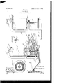
In the drawings, Figure `1 is a perspective of the invention; Fig. 2, a side elevation of the standard supporting the circular canopener; Fig. 8, a plan of the can-support, and Fig. 4 a detail perspective of the cuttingblade.
Like letters of reference refer to like parts in the several figures of the drawings.
The letter A designates a base-plate of any desired construction or configuration, which is provided at one side with a standard A extending upward therefrom and provided with a laterally-extending head A2. Intermediate of this head and the base is a threaded arm A3, through which the screwB passes, and is provided at its upper end with a canholding plate B secured thereto, while the lower end of the screw is provided with an operating-handle B2, as shown. The upper face of the can-holding plate B is provided with any desired means, such as a roughened face B2, for preventing a slipping or relative movement of thecan thereon. as the parts are rotated, one form of which is shown in Fig. 3.
The head A2 is provided with a longitudinal slot A2', as shown by dotted lines in Fig. 2, and also with a depending centering-pin A4, adapted to engage the can as the same is forced upward into contact with the cuttingblade C, which is supported in the slot A3 by means of its shank C extending through the slot and provided with a clamping-nut C2 upon the upper face of the head. The cutting-blade is thus adjustably mounted for movement relative to the centering pin, whereby an opening of different sizes may be made in the can, as found desirable. This cutting-blade is sharpened upon its opposite edges, as shown in Fig. 4, and provided with shoulders C3, which rest against the under face of the head to support the blade and to permit its reversal in order to use both edges thereof.
For the purpose of supporting the rectangular cutter D in position the base A is provided with upwardly extending lugs A, spaced apart and to the upper ends of which the side bars D are pivotally connected, each being provided with a knife or cutting edge D2, while the end bar D3 of the frame is provided with a similar edge D and with an operating-handle D5. The base is formed with a stop-fiange A6v at its end next the handle, against which the end of the can abuts when it is placed beneath this cutter.
In the operation of the invention the can is supported upon the plate carried by the screw, which when rotated carries the can upward until it engages the centering-pin and cutterblade, at which time the continued movement of the screw causes these points to puncture the can-top, and owing to the rotary movement of the can the blade continues its cut in a circular path until the top is severed from the can, when the parts may be quickly Withdrawn by reversing the direction of rotation of the screw.
The invention presents a simple and eflicient construction for yquickly opening Vcans Y and avoids the necessity for holding the can in the hand or for manually operating the cutter-blade during the opening, thus obviating the soiling of the hands and the contact of liquid or other contents of the can and also the frequent injury caused by slipping of a blade of the opener when carried by the hand.
Having described my invention and set forth its merits, what I claim, and desire to secure by Letters Patent, is-
l. Abase provided with astandard having a laterally-extending head, a cutting-blade fixed to said head relative to a can, a supporting arm carried by said standard, a screw mounted upon said arm, and a can-support secured to the upper end of said screw to rotate therewith and move the can into cutting relation with said blade.
IOO
2. Abase provided With a standardhaving va laterally-extending head, a cutting-blade fixed to said head relative to a can, a supportingarm carried by said standard, a 5 screw mounted upon said arm, a can-support secured to the upper end of said screw to rotate therewith and move the oaninto out ting relation With said blade, a centering-pin carried by the head in alinernent With said screw, and means for adjusting said outting- Io blade relative to said pin.
In testimony whereof Iyafx my signature in presence of two Witnesses.
JAMES WALTER DAVIS.
Witnesses:
T. J. ALEXANDER, J. H. HOGAN.
Priority Applications (1)
| Application Number | Priority Date | Filing Date | Title |
|---|---|---|---|
| US26508405A US809673A (en) | 1905-06-13 | 1905-06-13 | Can-opener. |
Applications Claiming Priority (1)
| Application Number | Priority Date | Filing Date | Title |
|---|---|---|---|
| US26508405A US809673A (en) | 1905-06-13 | 1905-06-13 | Can-opener. |
Publications (1)
| Publication Number | Publication Date |
|---|---|
| US809673A true US809673A (en) | 1906-01-09 |
Family
ID=2878154
Family Applications (1)
| Application Number | Title | Priority Date | Filing Date |
|---|---|---|---|
| US26508405A Expired - Lifetime US809673A (en) | 1905-06-13 | 1905-06-13 | Can-opener. |
Country Status (1)
| Country | Link |
|---|---|
| US (1) | US809673A (en) |
-
1905
- 1905-06-13 US US26508405A patent/US809673A/en not_active Expired - Lifetime
Similar Documents
| Publication | Publication Date | Title |
|---|---|---|
| US11618661B2 (en) | Container opener | |
| US809673A (en) | Can-opener. | |
| US1397537A (en) | Can-opener | |
| US1080636A (en) | Can-opener. | |
| US2318350A (en) | Can opener | |
| US778112A (en) | Can-opener. | |
| US499650A (en) | Bread-knife | |
| US992635A (en) | Can-opener. | |
| US598065A (en) | Rotary can-opener | |
| US1517955A (en) | Can opener | |
| US2429885A (en) | Can opener | |
| US613076A (en) | Can-opener | |
| US529849A (en) | Can-opener | |
| US2602218A (en) | Double-action can opener and bottle cap remover | |
| US1371657A (en) | Can-opener | |
| US587419A (en) | Can-opener | |
| US466193A (en) | Can-opener | |
| US877974A (en) | Can-opener. | |
| US588911A (en) | Can-opener | |
| US2043654A (en) | Combined can opener and can perforator | |
| US638597A (en) | Can-cutting machine. | |
| US592129A (en) | Can-opener | |
| US576547A (en) | Thirds to f | |
| DE185167C (en) | ||
| US609413A (en) | Can-opener |