US809667A - Guard for vent-pipes. - Google Patents
Guard for vent-pipes. Download PDFInfo
- Publication number
- US809667A US809667A US18159503A US1903181595A US809667A US 809667 A US809667 A US 809667A US 18159503 A US18159503 A US 18159503A US 1903181595 A US1903181595 A US 1903181595A US 809667 A US809667 A US 809667A
- Authority
- US
- United States
- Prior art keywords
- guard
- ribs
- vent
- pipes
- bars
- Prior art date
- Legal status (The legal status is an assumption and is not a legal conclusion. Google has not performed a legal analysis and makes no representation as to the accuracy of the status listed.)
- Expired - Lifetime
Links
- 238000010276 construction Methods 0.000 description 3
- 238000009423 ventilation Methods 0.000 description 2
- 239000000463 material Substances 0.000 description 1
- 239000002184 metal Substances 0.000 description 1
Images
Classifications
-
- F—MECHANICAL ENGINEERING; LIGHTING; HEATING; WEAPONS; BLASTING
- F24—HEATING; RANGES; VENTILATING
- F24F—AIR-CONDITIONING; AIR-HUMIDIFICATION; VENTILATION; USE OF AIR CURRENTS FOR SCREENING
- F24F7/00—Ventilation
- F24F7/02—Roof ventilation
Definitions
- This invention relates to guards for the end of a vent or ventilation pipe; and the ob j ect thereof is to provide an improved device of this class which is designed to prevent articles of various kinds and classes from entering such pipes or being thrown thereinto; and with these and other objects in view the invention consists in a device of the class specilied constructed as hereinafter described and claimed.
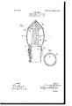
- My improved ventilationpipe guard comprises a body portion b, which is preferably barrel-shaped in form and which consists of a plurality of vertically-arranged ribs 6 which are closely adjacent and which are preferably corrugated transversely, as shown in Fig. 1.
- the ribs b are connected at their lower ends with a pipe member b into which the end of the pipe a is adapted to be inserted, and the upper end of the pipe member b is preferably flared outward slightly, as shown at Z), and is provided on the inner side thereof in the form of construction shown in Fig. 1 with an inwardly-di rected flange or rim 7), which rests on the top of the pipe (1, as clearly shown.
- the upper ends of the ribs 1) are connected with an annular band b, above which the form of the guard is preferably conical and composed of ribs 7), similar to ribs 6
- the annular band I) is also preferably provided with a projecting flange or rim b and the entire guard is preferably cast from any suitable metal but it will be apparent that the said guard may, if desired, be composed of separate parts secured together in any desired manner and the form of the top portion thereof may be varied within certain limits without departing from the spirit of my invention or sacrificing its advantages.
- Fig. 1 of the drawings I have only shown a part of the ribs b but the form of the device in cross-section is clearly indi cated in Fig. 2, and while I have shown and described the ribs b as being corrugated transversely it will be apparent that this form of construction is not absolutely necessary, and said ribs may be placed so close to gether as to prevent articles of any material size from being thrown into the pipe at or from dropping thereinto.
- a guard for vent pipes comprising a plurality of vertically-disposed ribs or bars connected at their lower ends with a circular bottom portion, adapted to be placed on a vent or ventilating pipe, and at their upper ends with a conical top having similar ribs or bars all of said ribs or bars being corrugated, substantially as described.
- a guard for vent pipes comprising a body portion composed of a plurality of vertically arranged flat ribs or bars, having their greatest extent in a radial direction, said ribs or bars being connected at their lower ends with a pipe member adapted to be secured to a vent or ventilating pipe and at their upper ends with a band forming the lower part of a conical top having similarlydisposed flat bars, all of said ribs or bars being corrugated, substantially as described.
- a guard for vent pipes comprising a bottom portion of unbroken circular form a, body portion composed of flat ribs or bars having their greatest extent in a radial direction and a conical top portion having similarly-disposed flat bars, the top bars not being continuous
- those of the body por- I my inventionl have signed my name, in prestion but united thereto by a ring or band to ence of the subscribing witnesses, this 16th Which both seriesrof bars are connected, the day of November, 1903.
Landscapes
- Engineering & Computer Science (AREA)
- Chemical & Material Sciences (AREA)
- Combustion & Propulsion (AREA)
- Mechanical Engineering (AREA)
- General Engineering & Computer Science (AREA)
- Orthopedics, Nursing, And Contraception (AREA)
Description
No. 809,667. PATENTEDJAN. 9, 1906. C. M. BREEN,
GUARD FOR VENT PIPES.
APPLICATION FILED NOV. 18. 1903.
WITNESSES. INVENTOR 4 TTOIMEYS CORNELIUS M. BREEN,
OF NEW YORK, N. Y.
GUARD FOR VENT-PIPES.
Specification of Letters Patent.
Patented Jan. 9, 1906.
Application filed November 18,1903. Serial No. 181,595.
To all 7071/0111 if 'IIbU/U concern.-
Be it known that I, CORNELIUS M. BREEN, a citizen of the United States, residing at New York, in the county of New York and State of New York, have invented certain new and useful Improvements in Guards for I ent-Pipes, of which the following is a specification, such as will enable those skilled in the art to which it appertains to make and use the same.
This invention relates to guards for the end of a vent or ventilation pipe; and the ob j ect thereof is to provide an improved device of this class which is designed to prevent articles of various kinds and classes from entering such pipes or being thrown thereinto; and with these and other objects in view the invention consists in a device of the class specilied constructed as hereinafter described and claimed.
The invention is fully disclosed in the following specification, of which the accompanying drawings form a part, in which the separate parts of my invention are designated by suitable reference characters in each of the views, and in which- Figure 1 is a central vertical section of the end of a ventilation-pipe provided with my improved guard; Fig. 2, diagrammatic section of the guard on the line 2 2 of Fig. 1.
In the drawings forming part of this specification I have shown at a an ordinary vent or ventilation pipe of the class which are usually projected through the roof of a building or some other part thereof, and in the practice of my invention I provide a guard for the end of this pipe which is of the following construction: My improved ventilationpipe guard comprises a body portion b, which is preferably barrel-shaped in form and which consists of a plurality of vertically-arranged ribs 6 which are closely adjacent and which are preferably corrugated transversely, as shown in Fig. 1. The ribs b are connected at their lower ends with a pipe member b into which the end of the pipe a is adapted to be inserted, and the upper end of the pipe member b is preferably flared outward slightly, as shown at Z), and is provided on the inner side thereof in the form of construction shown in Fig. 1 with an inwardly-di rected flange or rim 7), which rests on the top of the pipe (1, as clearly shown. The upper ends of the ribs 1) are connected with an annular band b, above which the form of the guard is preferably conical and composed of ribs 7), similar to ribs 6 The annular band I) is also preferably provided with a projecting flange or rim b and the entire guard is preferably cast from any suitable metal but it will be apparent that the said guard may, if desired, be composed of separate parts secured together in any desired manner and the form of the top portion thereof may be varied within certain limits without departing from the spirit of my invention or sacrificing its advantages.
In Fig. 1 of the drawings I have only shown a part of the ribs b but the form of the device in cross-section is clearly indi cated in Fig. 2, and while I have shown and described the ribs b as being corrugated transversely it will be apparent that this form of construction is not absolutely necessary, and said ribs may be placed so close to gether as to prevent articles of any material size from being thrown into the pipe at or from dropping thereinto.
Having fully described my invention, what I claim as new, and desire to secure by Letters Patent, is
1. A guard for vent pipes, comprising a plurality of vertically-disposed ribs or bars connected at their lower ends with a circular bottom portion, adapted to be placed on a vent or ventilating pipe, and at their upper ends with a conical top having similar ribs or bars all of said ribs or bars being corrugated, substantially as described.
2. A guard for vent pipes, comprising a body portion composed of a plurality of vertically arranged flat ribs or bars, having their greatest extent in a radial direction, said ribs or bars being connected at their lower ends with a pipe member adapted to be secured to a vent or ventilating pipe and at their upper ends with a band forming the lower part of a conical top having similarlydisposed flat bars, all of said ribs or bars being corrugated, substantially as described.
3. A guard for vent pipes, comprising a bottom portion of unbroken circular form a, body portion composed of flat ribs or bars having their greatest extent in a radial direction and a conical top portion having similarly-disposed flat bars, the top bars not being continuous With those of the body por- I my inventionlhave signed my name, in prestion but united thereto by a ring or band to ence of the subscribing witnesses, this 16th Which both seriesrof bars are connected, the day of November, 1903.
outer surface of the top bars being flush With CORNELIUS M. BREEN. 5 the outer surface of the said ring or band sub- Witnesses:
stantially as described. F. A. STEWART,
In testimony that I claim the foregoing as C. J. KLEIN.
Priority Applications (1)
| Application Number | Priority Date | Filing Date | Title |
|---|---|---|---|
| US18159503A US809667A (en) | 1903-11-18 | 1903-11-18 | Guard for vent-pipes. |
Applications Claiming Priority (1)
| Application Number | Priority Date | Filing Date | Title |
|---|---|---|---|
| US18159503A US809667A (en) | 1903-11-18 | 1903-11-18 | Guard for vent-pipes. |
Publications (1)
| Publication Number | Publication Date |
|---|---|
| US809667A true US809667A (en) | 1906-01-09 |
Family
ID=2878148
Family Applications (1)
| Application Number | Title | Priority Date | Filing Date |
|---|---|---|---|
| US18159503A Expired - Lifetime US809667A (en) | 1903-11-18 | 1903-11-18 | Guard for vent-pipes. |
Country Status (1)
| Country | Link |
|---|---|
| US (1) | US809667A (en) |
Cited By (1)
| Publication number | Priority date | Publication date | Assignee | Title |
|---|---|---|---|---|
| US20030110554A1 (en) * | 2001-12-17 | 2003-06-19 | Andre Hernandez | Roof vent ingress prevention device |
-
1903
- 1903-11-18 US US18159503A patent/US809667A/en not_active Expired - Lifetime
Cited By (2)
| Publication number | Priority date | Publication date | Assignee | Title |
|---|---|---|---|---|
| US20030110554A1 (en) * | 2001-12-17 | 2003-06-19 | Andre Hernandez | Roof vent ingress prevention device |
| US6959457B2 (en) * | 2001-12-17 | 2005-11-01 | Andre Hernandez | Roof vent ingress prevention device |
Similar Documents
| Publication | Publication Date | Title |
|---|---|---|
| US809667A (en) | Guard for vent-pipes. | |
| US633343A (en) | Nipple. | |
| US694736A (en) | Liner for centrifugal liquid-separators. | |
| US1175237A (en) | Silo. | |
| US985152A (en) | Power-wheel. | |
| US391902A (en) | Ventilator | |
| US917450A (en) | Sheave. | |
| US715968A (en) | Ventilator. | |
| US535276A (en) | Hermann doerge | |
| US491678A (en) | Chimney-top | |
| US399594A (en) | Chimney cap and protector | |
| US408907A (en) | Dust-collector | |
| US1326523A (en) | Ventilator and chimney-cap. | |
| US350800A (en) | Thomas j | |
| US3610A (en) | And thos | |
| US397669A (en) | David teets | |
| US472661A (en) | Edwin h | |
| US1037286A (en) | Ventilator and chimney-cap. | |
| US156288A (en) | Improvement in cones for smoke-stacks | |
| US937254A (en) | Ventilator. | |
| US521689A (en) | William h | |
| US357017A (en) | mckekna | |
| US657812A (en) | Draft device. | |
| US199599A (en) | Improvement in ventilator and chimney-cap | |
| US391503A (en) | Half to george e |