US809606A - Game apparatus. - Google Patents
Game apparatus. Download PDFInfo
- Publication number
- US809606A US809606A US27229205A US1905272292A US809606A US 809606 A US809606 A US 809606A US 27229205 A US27229205 A US 27229205A US 1905272292 A US1905272292 A US 1905272292A US 809606 A US809606 A US 809606A
- Authority
- US
- United States
- Prior art keywords
- alley
- extension
- pin
- pins
- extensions
- Prior art date
- Legal status (The legal status is an assumption and is not a legal conclusion. Google has not performed a legal analysis and makes no representation as to the accuracy of the status listed.)
- Expired - Lifetime
Links
Images

Classifications
-
- A—HUMAN NECESSITIES
- A63—SPORTS; GAMES; AMUSEMENTS
- A63D—BOWLING GAMES, e.g. SKITTLES, BOCCE OR BOWLS; INSTALLATIONS THEREFOR; BAGATELLE OR SIMILAR GAMES; BILLIARDS
- A63D5/00—Accessories for bowling-alleys or table alleys
- A63D5/08—Arrangements for setting-up or taking away pins
-
- A—HUMAN NECESSITIES
- A63—SPORTS; GAMES; AMUSEMENTS
- A63D—BOWLING GAMES, e.g. SKITTLES, BOCCE OR BOWLS; INSTALLATIONS THEREFOR; BAGATELLE OR SIMILAR GAMES; BILLIARDS
- A63D5/00—Accessories for bowling-alleys or table alleys
- A63D5/08—Arrangements for setting-up or taking away pins
- A63D2005/086—Pivotable pins
Definitions
- This invention has for its object the pro- .duction of a novel game apparatus of the general character of the well-known bowlingalley, but embodying various novel features whereby the game may be played in a more convenient manner.
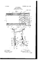
- Figure 1 is a side elevation, centrally broken out, of a game apparatus embodying my invention.
- Fig. 2 is a' top plan view of the right-hand end thereof, viewing Fig. 1, showing the pin-supporting frame and the resetting means.
- Fig. 3 is a transverse sectional detail on the line 3 3, Fig. 2, looking toward the left, and omitting the pins and their supporting-frame.
- Fig. 4 is an enlarged side elevation of one of the two-part pins with-its extension or obstacle portion in normal position; and
- Fig. 5 is a similar view, 7 but showing the extension in inoperative position, the upper part of the pin being broken out.
- the elongated alley 1 shown as rectangular in form, is made of suitable length and width in accordance with the dimensions desired for the apparatus, a longitudinal gutter 2 being formed at each side of the alley, inclosed by side boards 3, the whole being firmly sustained on upright legs or standards 4, Fig. 1.
- a cross-board 5 is provided, faced with a suitable cushion, as 6, Fig. 2, the alley terminating at the dotted line 7, Fig. 2, and between such termination and the crossboard I form a boxlike pocket 8, having its bottom 9 inclined transversely. (See Fig. 3.)
- the adjacent ends of the gutters open into the pocket by omitting the inner lip of each gutter, as at 10, so that a ball rolling off the alley and into a gutter will pass thence into the pocket.
- the pocket communicates at 11 Fig. 3, with one end of a returnconduit 12, located beneath the alley and extended toward the front end thereof on an incline, the front end of the conduit being closed, as at 13. (See dotted lines, Fig. 1.)
- a ball deposited in the pocket passes therefrom through the opening 11 into the conduit and rolls down the same to the front end in readiness to be used by the player, several balls 14 being shown in Fig. 1.
- a frame or grating comprising side bars 15, Fig. 2, and connecting crossbars 16, the frame being rigidly secured to the side boards 3 of the alley by upright posts 17.
- Two meeting diagonals 18 on the crossbars form with the rearmost of said bars a triangle, the triangle being herein shown as provided with ten annular bosses 19, one at the apex of the triangle and the others in rows of two, three, and four, substantially as the pins are positioned in the ordinary bowling-alley.
- Each boss forms an overhead" support from which depends a two-part pinlike member, and as said members are similar in construction only one will be described in detail. Having more particular reference to Figs.
- each of said members comprises an upper part 20, made as a cylindrical in adapted to snugly fit into a boss 19 and field in vertically-adjusted position therein by a set-screw 21, the lower end of the part 20 being cut on a bevel at 22 on a diagonal plane transverse to the length of the alley.
- the beveled end is faced toward the crossboard 5, and the second portion 23 of the pin, termed an extension, is pivotally connected by a hinge 24 with the fixed part 20, the upper end of the extension being beveled at 25.
- the extension 23 is alined with the fixed part of the pin and depends therefrom, it being yieldingly held in such position by a light spring 26, connected at its ends to the two parts 20 23 of the pin at one side of the pivotal connection 24.
- a light spring 26 connected at its ends to the two parts 20 23 of the pin at one side of the pivotal connection 24.
- the extension In order to lighten the extension, it is cut away at its rear side at 27, thelower extremities of the several extensions closely approaching the surface of the alley l to be in the path of a ball traversing the latter.
- a resetting member shown as a triangular frame 29, movable in a vertical plane and having one side long enough to depend below the pivot 24 on which the extension is hung, the normal position of the resetting member bein shown in Figs. 1 and-4.
- a wire or cord 30, fastened to the corner 31 of said member leads back to a pin 32 on a rocking bar 33, mounted in the endmost posts 17, a series of seven pins being provided, the connections 30 being slack when the extensions 23 are in normal position.
- a counterweight 34 Fig.
- An elongated, rectangular alley having a pocket at one end, and a return-duct leading from the pocket to the op osite end of the alley, a group of pins fixed y suspended above the alley in front of the pocket, a normally depending, pivotally-connected extension oneach pin, adapted to be hit and swung upward by a ball traversing the alley, a single instrumentality to automatically-lock an extension in either its depending, normal position, or in abnormal position when swung upward, and manually-controlled means to simultaneously restore to depending position such extensions as have been swung upward.
- An elongated, rectangular alley a group of pins fixedly suspended above one end thereof and beveled at their lower ends, an extension pivotally connected with each pin and beveled correspondingly, a spring to retain the beveled portions of the pin and extension in contact and thereby maintain the extension alined with the pin, and also to retain the extension elevated when swung rearwardly, a resetting member for each extension, and manually-controlled means to act through the resetting members of all abnormally-positioned extensions and simultaneously reset them.
- An elongated alley having a pocket at one end and longitudinal side gutters leading thereto, a return-conduit from the pocket to the opposite end of the alley, a group of vertically-adjustable, two-part pins suspended above the alley, in front of the pocket, the lower part or extension of each pin being pivoted to the fixed upper part, a single instrumentality to hold the extensions in alinement with the upper parts, and also at an angle thereto when struck by a ball traversing the alley, and means manually operated from the front end of the alley to simultaneously restore to alined position all extensions which have been previously moved into abnormal position.
- An elongated alley an overhead frame at one end, a group of triangularly-arranged pins suspended from the frame, a depending extension pivoted on the lower end of each pin and normally in alinement therewith and in the path of a ball traversing the alley, engagement of the ball with an extension swinging the latter u ward, a singleinstrumentality to automatica 1y retain the extensions in depending or in upturned position, and manually-controlled means to reset the extensions in depending position, in alinement with the pins to which they are pivoted.
Landscapes
- Pinball Game Machines (AREA)
Description
2 SHBETSSHEET 1.
; fieaebm 60.3607 7051,
57 M @"7' ag.
m someoe.
PATENTED JAN. 9, 1906.
F. W. BURNS.
GAME APPARATUS.
APPLICATION nun we. 2.1905.
2 SHEETS-SHEET 2.
$22: A2: X i
j 0 w 5 MI g" v UNITED STATES PATENT OFFICE.
GAME APPARATUS.
Specification of Letters Patent.
Patented Jan. 9, 1906.
Application filed August 2, 1905. Serial No. 272,292.
To all whmn it may concern.-
Be it known that I, FREDERICK W. BURNS, a citizen of the United States, and a resident of Boston, county of Sufiolk, State of Massachusetts, have invented an Improvement in Game Apparatus, of which the following description, in connection with the accompanying drawings, is a specification, like numerals on the drawings representing like parts.
This invention has for its object the pro- .duction of a novel game apparatus of the general character of the well-known bowlingalley, but embodying various novel features whereby the game may be played in a more convenient manner.
In the ordinary bowling-alley a group of pins is set up at the end of the alley and the player rolls balls thereon with the object of hitting and knocking ,down as many of the pins as possible in the fewest number of shots. The pins must be set up one by one by hand and placed on their marks and the balls returned to the front or playing end of the alley, requiring an attendant to perform this work.
In my present invention instead of the usual pins I suspend above the alley a group of pin-like members or obstacles so mounted that when hit by a ball they will be swung up out of normal position, means being provided to automatically. retain them in such abnormal position after the ball passes through the grou I have also provided means whereby all of the displaced or abnormally-positioned members can be manually reset simultaneously from the front end of the alley. Means have also been provided to effect automatically the return of the balls from the rear to the front end of the alley.
The various novel features of my invention will be fully described in the subjoined specification and particularly pointed out in the following claims.
Figure 1 is a side elevation, centrally broken out, of a game apparatus embodying my invention. Fig. 2 is a' top plan view of the right-hand end thereof, viewing Fig. 1, showing the pin-supporting frame and the resetting means. Fig. 3 is a transverse sectional detail on the line 3 3, Fig. 2, looking toward the left, and omitting the pins and their supporting-frame. Fig. 4 is an enlarged side elevation of one of the two-part pins with-its extension or obstacle portion in normal position; and Fig. 5 is a similar view, 7 but showing the extension in inoperative position, the upper part of the pin being broken out.
Referring to the drawings, the elongated alley 1, shown as rectangular in form, is made of suitable length and width in accordance with the dimensions desired for the apparatus, a longitudinal gutter 2 being formed at each side of the alley, inclosed by side boards 3, the whole being firmly sustained on upright legs or standards 4, Fig. 1. At one end of the alley a cross-board 5 is provided, faced with a suitable cushion, as 6, Fig. 2, the alley terminating at the dotted line 7, Fig. 2, and between such termination and the crossboard I form a boxlike pocket 8, having its bottom 9 inclined transversely. (See Fig. 3.)
As shown in Fig. 2, the adjacent ends of the gutters open into the pocket by omitting the inner lip of each gutter, as at 10, so that a ball rolling off the alley and into a gutter will pass thence into the pocket.
At its deeper side the pocket communicates at 11 Fig. 3, with one end of a returnconduit 12, located beneath the alley and extended toward the front end thereof on an incline, the front end of the conduit being closed, as at 13. (See dotted lines, Fig. 1.)
A ball deposited in the pocket passes therefrom through the opening 11 into the conduit and rolls down the same to the front end in readiness to be used by the player, several balls 14 being shown in Fig. 1.
Above the end of the alley adjacent the pocket I mount a frame or grating comprising side bars 15, Fig. 2, and connecting crossbars 16, the frame being rigidly secured to the side boards 3 of the alley by upright posts 17. Two meeting diagonals 18 on the crossbars form with the rearmost of said bars a triangle, the triangle being herein shown as provided with ten annular bosses 19, one at the apex of the triangle and the others in rows of two, three, and four, substantially as the pins are positioned in the ordinary bowling-alley. Each boss forms an overhead" support from which depends a two-part pinlike member, and as said members are similar in construction only one will be described in detail. Having more particular reference to Figs. 4 and 5, each of said members comprises an upper part 20, made as a cylindrical in adapted to snugly fit into a boss 19 and field in vertically-adjusted position therein by a set-screw 21, the lower end of the part 20 being cut on a bevel at 22 on a diagonal plane transverse to the length of the alley.
The beveled end is faced toward the crossboard 5, and the second portion 23 of the pin, termed an extension, is pivotally connected by a hinge 24 with the fixed part 20, the upper end of the extension being beveled at 25. When the two beveled ends 22 25 are engaged, as in Fig. 4, the extension 23 is alined with the fixed part of the pin and depends therefrom, it being yieldingly held in such position by a light spring 26, connected at its ends to the two parts 20 23 of the pin at one side of the pivotal connection 24. In order to lighten the extension, it is cut away at its rear side at 27, thelower extremities of the several extensions closely approaching the surface of the alley l to be in the path of a ball traversing the latter.-
Referring to Fig. 1, all of the pin members are shown with the extensions set or in operative position, forming obstacles for the ball, it being the object of the player to hit and swing up as many as possible of the extensions with each ball rolled down the alley. When an extension is struck by a ball, it is swun upward and rearward on its pivot 24, and t e spring 26 is thereby carried to the opposite side of the pivot, as shown in Fig. 5, the tension of the spring acting to hold the extension in such abnormal or inoperative position, so that when the number of balls constituting a turn have been rolled the player can ascertain his score by counting the number of abnormally-positioned extensions. The extensions must now be reset in readiness for the next player, and I have provided manually-controlled means for such resetting. At the back of each fixed part 20 of a pin I fulcrum at 28 a resetting member, shown as a triangular frame 29, movable in a vertical plane and having one side long enough to depend below the pivot 24 on which the extension is hung, the normal position of the resetting member bein shown in Figs. 1 and-4. A wire or cord 30, fastened to the corner 31 of said member, leads back to a pin 32 on a rocking bar 33, mounted in the endmost posts 17, a series of seven pins being provided, the connections 30 being slack when the extensions 23 are in normal position. A counterweight 34, Fig. 1, keeps the rocking bar in the position shown, an arm 35 rearwardly extended from the bar having attached to it a flexible connection 36, which is led around a guide-sheave 37 beneath the alley to the front end thereof and attached to a handle 38, pivoted on one of the supports 4. By pulling the handle in the direction of arrow 39, Fig. 1, the rocking bar is turned to swing the pins 32 rearward or to the right, viewing Fig. 1, tightening the cords or wires 30.
When an extension 23 is swung into abnormal position, Fig. 5, it acts to swing the triangular resetting member 29 on its pivot 28 into the position shown, and its cord or wire.
30 is then tightened. If, then, the rocking bar 33 be turned as described, all of the cords or wires 30, which are already taut, will be pulled rearward, thereby swinging down the triangular members 29 and pressing the extensions 23 back into normal operative position in alinement with their fixed parts 20, the springs 26 being by such movement carried pack into retaining position, as shown in The balls are returned automatically to the front of the alley, and by the resetting means'just described the extensions, one or all, can be reset from the front end of the a ey.
Referring to Fig. 2, it will'beseenthat the two pin-like members in the second row are directly in front of two others in the rear or fourth row and the front or apex member is in front of a member in the third row, andin order to let the connections 30. from the said two members in the front row and from the apex member pass rearward the members behind have their fixediparts apertured, as at 40, Fig. 5, one of the connections 3O passing through each aperture. Thus the three pins 32 nearest the center of the series have each two connections secured to them, the other four pins having only one connection 30 attached to each.
Various changes in details maybe made without departingfrom the spirit andscope of my invention, one practical embodiment thereof being herein shown and described.
. Having fully described my invention, what I claim as new, and desire to secure by Letters Patent, is-
1. An elongated, rectangular alley having a pocket at one end, and a return-duct leading from the pocket to the op osite end of the alley, a group of pins fixed y suspended above the alley in front of the pocket, a normally depending, pivotally-connected extension oneach pin, adapted to be hit and swung upward by a ball traversing the alley, a single instrumentality to automatically-lock an extension in either its depending, normal position, or in abnormal position when swung upward, and manually-controlled means to simultaneously restore to depending position such extensions as have been swung upward.
2. An elongated ,rectangular alley, a group of swinging pin like members suspended above the alley in frontof the pocket and normally depending toward the alley, a spring connected with each member to retain it either in normal, or in abnormal position, and means to simultaneously restore to normal position all members abnormally positioned. Y
3. An elongated, rectangular alley, a group of pins fixedly suspended above one end thereof and beveled at their lower ends, an extension pivotally connected with each pin and beveled correspondingly, a spring to retain the beveled portions of the pin and extension in contact and thereby maintain the extension alined with the pin, and also to retain the extension elevated when swung rearwardly, a resetting member for each extension, and manually-controlled means to act through the resetting members of all abnormally-positioned extensions and simultaneously reset them.
4. An elongated alley having a pocket at one end and longitudinal side gutters leading thereto, a return-conduit from the pocket to the opposite end of the alley, a group of vertically-adjustable, two-part pins suspended above the alley, in front of the pocket, the lower part or extension of each pin being pivoted to the fixed upper part, a single instrumentality to hold the extensions in alinement with the upper parts, and also at an angle thereto when struck by a ball traversing the alley, and means manually operated from the front end of the alley to simultaneously restore to alined position all extensions which have been previously moved into abnormal position.
5. An elongated alley, an overhead frame at one end, a group of triangularly-arranged pins suspended from the frame, a depending extension pivoted on the lower end of each pin and normally in alinement therewith and in the path of a ball traversing the alley, engagement of the ball with an extension swinging the latter u ward, a singleinstrumentality to automatica 1y retain the extensions in depending or in upturned position, and manually-controlled means to reset the extensions in depending position, in alinement with the pins to which they are pivoted.
In testimony whereof I have signed my name to this specification in the presence of two subscribing witnesses.
FREDERICK W. BURNS.
Witnesses:
JOHN C. EDWARDS, ELIZABETH R. MORRISON
Priority Applications (1)
| Application Number | Priority Date | Filing Date | Title |
|---|---|---|---|
| US27229205A US809606A (en) | 1905-08-02 | 1905-08-02 | Game apparatus. |
Applications Claiming Priority (1)
| Application Number | Priority Date | Filing Date | Title |
|---|---|---|---|
| US27229205A US809606A (en) | 1905-08-02 | 1905-08-02 | Game apparatus. |
Publications (1)
| Publication Number | Publication Date |
|---|---|
| US809606A true US809606A (en) | 1906-01-09 |
Family
ID=2878087
Family Applications (1)
| Application Number | Title | Priority Date | Filing Date |
|---|---|---|---|
| US27229205A Expired - Lifetime US809606A (en) | 1905-08-02 | 1905-08-02 | Game apparatus. |
Country Status (1)
| Country | Link |
|---|---|
| US (1) | US809606A (en) |
Cited By (1)
| Publication number | Priority date | Publication date | Assignee | Title |
|---|---|---|---|---|
| US2467549A (en) * | 1946-08-03 | 1949-04-19 | Roscoe F Ely | Target for ball games |
-
1905
- 1905-08-02 US US27229205A patent/US809606A/en not_active Expired - Lifetime
Cited By (1)
| Publication number | Priority date | Publication date | Assignee | Title |
|---|---|---|---|---|
| US2467549A (en) * | 1946-08-03 | 1949-04-19 | Roscoe F Ely | Target for ball games |
Similar Documents
| Publication | Publication Date | Title |
|---|---|---|
| US2587042A (en) | Target type toy with pivoted targets | |
| US731825A (en) | Game apparatus. | |
| US2118084A (en) | Golf game device | |
| US809606A (en) | Game apparatus. | |
| US1537809A (en) | Game apparatus | |
| US1994685A (en) | Mechanical baseball game | |
| US2211777A (en) | Bowling game | |
| US1196992A (en) | Game apparatus. | |
| US910608A (en) | Amusement device. | |
| US2188740A (en) | Portable bowling alley | |
| US1829239A (en) | Golf bowling game | |
| US1094559A (en) | Game apparatus. | |
| US1516887A (en) | Game apparatus | |
| US1116593A (en) | Game. | |
| US1821918A (en) | Basket ball game | |
| US809715A (en) | Bowling-alley. | |
| US2361482A (en) | Game apparatus having pieces setting-up means | |
| US1209113A (en) | Toy bowling-alley. | |
| US957472A (en) | Game apparatus. | |
| US831218A (en) | Parlor bowling-alley. | |
| US1396798A (en) | Baseball-game apparatus | |
| US1254958A (en) | Game apparatus. | |
| US1491888A (en) | Game apparatus | |
| US2683035A (en) | Bowling pin resetting apparatus | |
| US1694917A (en) | Toy |