US809598A - Hay-loader. - Google Patents
Hay-loader. Download PDFInfo
- Publication number
- US809598A US809598A US15243203A US1903152432A US809598A US 809598 A US809598 A US 809598A US 15243203 A US15243203 A US 15243203A US 1903152432 A US1903152432 A US 1903152432A US 809598 A US809598 A US 809598A
- Authority
- US
- United States
- Prior art keywords
- carrier
- frame
- shaft
- hay
- sprockets
- Prior art date
- Legal status (The legal status is an assumption and is not a legal conclusion. Google has not performed a legal analysis and makes no representation as to the accuracy of the status listed.)
- Expired - Lifetime
Links
- 230000033001 locomotion Effects 0.000 description 18
- 238000010276 construction Methods 0.000 description 10
- 230000003028 elevating effect Effects 0.000 description 4
- 230000002093 peripheral effect Effects 0.000 description 4
- 239000000969 carrier Substances 0.000 description 3
- 230000005484 gravity Effects 0.000 description 3
- 210000000707 wrist Anatomy 0.000 description 3
- 230000005540 biological transmission Effects 0.000 description 2
- 230000008933 bodily movement Effects 0.000 description 2
- 102000004726 Connectin Human genes 0.000 description 1
- 108010002947 Connectin Proteins 0.000 description 1
- 235000015842 Hesperis Nutrition 0.000 description 1
- 235000012633 Iberis amara Nutrition 0.000 description 1
- 229910000746 Structural steel Inorganic materials 0.000 description 1
- 230000000332 continued effect Effects 0.000 description 1
- 230000000694 effects Effects 0.000 description 1
- 239000000463 material Substances 0.000 description 1
- 229920000136 polysorbate Polymers 0.000 description 1
- 230000000284 resting effect Effects 0.000 description 1
- 239000011435 rock Substances 0.000 description 1
Images


Classifications
-
- A—HUMAN NECESSITIES
- A01—AGRICULTURE; FORESTRY; ANIMAL HUSBANDRY; HUNTING; TRAPPING; FISHING
- A01D—HARVESTING; MOWING
- A01D87/00—Loaders for hay or like field crops
- A01D87/02—Loaders for hay or like field crops with conveyor belts or conveyor chains, with or without pick-up means
Definitions
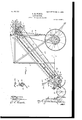
- This invention relates to improvements in hay-loaders of that type which arewheeled and serve to gather and transfer the hay from the swath or windrow to a wagon as the wagon and loader are drawn along together.
- the salient objects of the invention are to provide a machine in which the hay as it is gathered and elevated is automatically distributed over the length of the hayrack, but may nevertheless be discharged at any given point during a given period of time, if so desired; to provide a machine so organized and constructed that the dischargeapron,which delivers the hay, is automatically extended and retracted relatively to the main part of the loader; to provide in a machine of the character last referred to means whereby this automatic extension and retraction of the discharge apron or carrier is effected without changing the speed of movement of the conveyer or carrier belt; to provide in a machine of the character referred to a construction in Which that part of the carrier-belt which is automatically extended and retracted is arranged to loop back within and between the main upper and lower loops of the elevating portion of the carrier during the retracting movement, thereby taking care of the temporarily functionally inoperative portion of the carrier in a simple and practical way and without disarranging the latter; to provide in conjunction with the automatically extendible and retractable
- FIG. 5 is a view, partly in section and partly in elevation, taken on line 5 5 of Fig. 1 and looking in the direction of the arrows, parts being broken out to reduce the height of the figure.
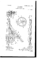
- Fig. 6 is a fragmentary detail, partly in side elevation and partly in vertical section, taken approximately on line 6 6 of Fig. 3 and looking in the direction of the arrows.
- Fig. 7 is a sectional view taken on line 7 7 of Fig.
- Fig. 8 is an elevation or face view of theremote side of the largest gear seen in Fig. 6.
- Fig. 9 is a horizontal sectional view taken on line 9 9 of Fig. 6 and looking downwardly.
- Fig. 10 is a fragmentary detail taken approximately on line 10 10 of Fig. 6, but including the extreme outer end of the carrier-frame and looking downwardly.
- Figs. 11 and 12 are front and side elevations, respectively, of one of the main carrier-sprockets located at the receiving end of the carrier and showing particularly the construction and arrangement of the pick-up fingers and coperating cam mechanism.
- Fig. 13 is a fragmentary plan view of the principal operative parts of the automatic hitching apparatus.
- Fig. 14 is a longitudinal vertical section taken on line 14 14 of Fig.
- Fig. 15 is a fragmentary cross-sectional view of the rake-head.
- Fig. 16 is a sectional view taken approximately on line 16 16 of Fig. 1 with parts brokenout.
- Fig. 17 is a sectional view taken on line 17 17 of Fig. 6.
- Fig. 18 is a sectional view taken on line 18 18 of Fig. 2.
- 1 designates as a- Patented Jan. 9, 1906.
- main wheeled supporting-frame comprising side frame members 2, front and rear cross frame members 3 and 4, respectively, (the former being shown in Fig. 13,) upright frame members 5 and 6 at each side of the machine, and diagonal brace members 7.
- the several frame members are conveniently formed of angle-iron and are so constructed and united as to form a rigid strong supporting-frame for the carrier mechanism. neath the forward part of the main frame is secured the main supporting-axle 8, provided with the usual supporting-wheels 9 at each end, while the rear end of the main frame is conveniently supported by means of a pair of caster-wheels 10, adjustably connected with the main frame, so that the latter may be raised or lowered, as indicated clearly at 11.
- both the frame members 12 and 13 are channel-shaped in cross-section, with their open sides facing in wardly for a purpose which will hereinafter appear.
- Describing next the rake or gathering mechanism, 14 designates a pair of brackets mounted upon the side frame members 2 near the rear ends of the latter and provided at their upper ends with sockets 15, within which are mounted the ends of a tubular rake head or bar 16.
- the spring rake-teeth 17 are shown as provided at their attached ends with the usual coils 18, which are arranged to encircle the tubular rake-head and terminate in upturned extensions 19, which extend through suitable apertures in the confining-bar 20.
- the confining-bar 20 is rigidly bolted to the upper side of the rake-head by means of bolts 21, arranged to extend vertically through said members at points between the raketeeth, as shown clearly in Fig. 3.
- a hand-lever 23 is rigidly connected with each end of the tubular rake-head, one end of each lever being arranged to traverse a notched segment 22, while the opposite end is provided with the usual handle and latchhandle 24.
- the handle 24 is arranged to control a spring-pressed dogging-latch 25, which cooperates with the notched segment 22 in the usual manner.
- the side frame members 2 are provided with depending brackets 26, having journal-bearings at their lower ends within which are seated the ends of a sprocket-shaft 27, carrying adjacent to each of its ends and inside of the respective brackets sprocket-wheels 28, which are rigidly mounted thereon.
- the carrier or conveyer belt extends around and is carried at its lower end by the sprockets 28.
- cooperating pick-up fingers which are constructed and arranged as follows: 30 and 31 respectively designate two fingershafts which are mounted to extend between the two main sprockets 28 at diametrically opposite sides of the latter and are mounted upon and carried by said sprockets.
- Said finger-shafts are each provided at each end with a crank extension 32, provided with a wrist portion 33, which extends through and is journaled within a suitable bearing-aperture in the periphery of the corresponding sprocket-wheel, the wrist being provided at the outer side of the sprocket with a crankarm 34, which in turn terminates in a cam projection 35, which is preferably surrounded by an antifriction-roller 36.
- 37 designates a peculiarly-shaped cam-block mounted rigidly upon the supporting-bracket 26 between the latter and the corresponding sprocket, the periphery of said camblock forming an irregularly-curved path or cam-surface 38, which is adapted to cooperate with the cam projection 36 of the crank 34.
- crank extensions 32 stand at obtuse angles in relation to the crank-arms 34, these relations being important in the operation of the device, as will now be explained.
- Each pick-up finger-shaft is provided with a series of straight rigid lingers 39, spaced at intervals apart and of a suitable length to reach rearwardly to and between the pairs of teeth of the rake as the pick-up-finger shafts are carried around during the revolution of the sprockets 28.
- the camblock therefore serves to hold the fingers rigid and in approximately radial relation to the sprocket until the fingers have reached a tween the slats of the upper lap of the carrier the cam projection 36 encounters the re' curved portion 38 of the'cam, which operates to tilt the fingers forwardly again to a position where the center of gravity falls outside of the axis ofthe wrists 33, whereupon the parts resume the position shown in Fig. 12, wherein the arm 34 rests in engagement with the stop 40.
- 41 designates a cross-shaft which is journaled in suitable bearings mounted upon the under side of the horizontal frame members 13.
- s rockets 42 Upon the shaft 41, at points between its ends and near the respective ends thereof, are rigidlymounted s rockets 42, which carry the sprocket-be ts of the carrier 29.
- sprockets 43 and 44 Upon the same shaft 41, at one end thereof, are rigidly mounted two other sprockets 43 and 44, res ectively, one of which carries the main d five-bclt 45, while the other carries a transmission belt 46, the main belt 45 being driven from a larger sprocket 47, mounted upon the main axle 8 of the wheel-frame.
- the shaft 41 imparts motion to all of the several drive-sprockets which actuate the carrier, said shaft will be hereinafter designated the main shaft.
- the carrier From the pair of sprockets 42 the carrier extends horizontally forward to and around a pair of sprockets 48, which are loosely mounted upon the shaft 49, the ends of which constitute trunnions 50, mounted in rollers 51, which are in turn confined to travel within the channels 52 of the frame members 13. From the sprockets 48 the carrier returns and passes over a pair of sprockets 53, rigidly mounted upon a shaft 54, which is j ournaled in suitable ournal-boxes 55, mounted upon the upper-sides of the respective frame members 12.
- the carrier From the sprockets 53 the carrier passes downwardly and around a pair of take-up sprockets 56, loosely ournaled upon a cross-shaft 57, which is exactly similar to the shaft 49 and is similarly provided at its ends with trunnions 58, engaged with rollers 59, which are confined and travel within the channels of the side frame members 12. From the sprockets 56 the carrier returns upwardly and passes around a pair of sprockets 61, rigidly mounted upon a shaft 62,which is in turn journaled in a pair of brackets 63, mounted upon the under sides of the respective frame members 12.
- the carrier is endless, and were the several supporting-sprockets mounted so as to be incapable of bodily movement the carrier would travel around the sprockets in the ordinary manner, the hay being delivered always at the extreme end of the horizontal extension.
- the main shaft 41 is provided adjacent to one end with a loosely-mounted spur-gear 68 and immediately adjacent thereto with a co operating clutch wheel 69, also loosely mounted upon the main shaft. (See also detail Figs.
- the clutch-wheel 69 IIO is provided with a peripheral series of notches 70, and adjacent thereto is mounted to reciprocate a vertically-movable dog 71, working through a suitable bearing 72, mounted upon the main side fi'ame member 13,
- the dog 71 is provided at a point coincident with the interior channeled portion of the frame member 13 with a horizontal offset portion 7 3 and also with a vertical extension 74, which extends downwardly to and projects through an opening in the upper side of the inclined frame member 12, so as to protrude within the channel of the latter.
- the lower end of the extension 74 terminates in a cam projection or shoe 75, which is located within the channel of the member 12 and is adapted to be acted upon by the trunnion roller 59, which carries the end of the shaft 57, as hereinbefore described.
- 7 6 designates a trippinglatch, mounted to reciprocate within the channeled portion of the horizontal member 13 and normally held projected by means'of a coiled spring 77, the engaging end of said latch be ing arranged to project beneath a shoulder 78, formed upon the dog 71, as shown clearly in detail, Fig. 7, in such manner as to hold the dog in its uplifted position.
- a rod-like extension 79 which extends forwardly some distance and terminates in a bumper 80, which is located in the path of the trunnion-roller 51, which carries the end of the shaft 49.
- a ratchet 81 (see Fig. 8,) with which ratchet is arranged to cooperate a radially-movable doggingpawl 82, mounted to reciprocate within a suitable way or bearing 83 upon the side face of the gear.
- the dogging-pawl is provided with a cam-stud 84, (see sectional Fig. 7,) which projects through a radial slot 85, formed in the gear 68 and engages at the opposite side of said gear an eccentrically dis posed and curved cam-slot 86, formed in the clutch-wheel 69.
- the relative arrangement and construction of these parts is such that when the spur-gear is rotated relatively to the clutch-wheel in one direction the dogging pawl will be withdrawn out of engagement with the ratchet 81 and when rotated in the opposite direction will be permitted to engage.
- gear and clutch-wheel are held in position to permit the doggingpawl to engage the ratchet by means of a spiral spring 87, the intermediate portion of which is coiled around the hub of the former, while one end is rigidly connected to the clutch-wheel, as indicated at 88, and the opposite end arranged to engage a stop-lug 89, mounted upon the gear.
- 90 designates a pinion loosely mounted upon the shaft 54 and arranged to intermesh with the gear 68.
- an endwise-shiftable clutch 91 Adjacent to the pinion 90 is mounted an endwise-shiftable clutch 91, which is provided with the usual clutch-teeth 92, arranged to engage corresponding recesses 93, formed in the proximate face of the pinion, said clutch being splined upon the shaft 54 and being actuated by means of a bell-crank lever 94, which terminates in a yoke 95, the ends of which engage the usual annular groove 96 upon the clutch. It is to be noted that this clutch 91 is so constructed as to lock the pinion rigid against rotation upon the shaft in either direction.
- a floating frame (designated as a whole 101, see Fig. 3,) composed of a series of longitudinal slats 102, united at their upper and lower ends by suitable cross-strips 103 and 104, respectively.
- This frame is arrangedto rest by gravity upon the carrier or hay carried thereby and is supported in this position by means of a pair of depending links 105, pivotally connected at their upper ends to the brackets 14, as indicated at 106, and suitably connected at their lower ends to the ends of cross-strip 104.
- a canvas wind-guard 107 which extends between the upper and lower laps of the extendible portion of the carrier and is retractable and extendible with the latter.
- the shaft 57 is provided with a pair of radial arms 56, to which the tension-chains 64, hereinbefore described, are connected, thereby holding said shaft against rotation and in a definite position.
- Said shaft is also provided at each end with an upstanding radial stud 108, between the upper ends the shaft 49 conveniently by being adj ustably buckled to the latter, so that the web may be held taut, as best shown in Fig. 4.
- a sleeve 110 which is provided externally with a spline 111, upon which is arranged to reciprocate a drum 112.
- a traction-cable 113 To the drum is attached one end of a traction-cable 113, the opposite end of which extends forwardly through a guide 114, mounted upon the ends of the hounds of the wheeled frame and terminates in an eyebar 115, adapted for attachment with a suitable stud carried by the axle of the wagon.
- the drum 112 is provided.
- a clutch 118 which has splined engagement with the axle and is toothed to engage the correspondingly-toothed end of the sleeve, as indicated at 119.
- the clutch 118 is provided with an annular groove, which is engaged by a yoke 120, forming the free end of a lever. 121, which is pivotally connected at its opposite end, as indicated at 122, to the frame member 118 or other suitable support.
- the eyebar 115 is provided in its upper face with a series of ratchetnotches 115, with which notches is arranged to cooperate a gravity-pawl 124, pivoted to the upper side of the guide 114and working through an opening in thelatter.
- the length of the traction-chain is so adjusted that the eyebar will be drawn within the guide 114 and in position for its notches to register, or approximately register, with the pawl 124 at the time the clutch 118 is thrown out of engagement with the sleeve.
- endless carrier herein shown is obviously an extremely practical and desirable construction, yet within the broader scope of'my invention I do not deem such an endless car rier essential, but, on the contrary, do not 7 limit myself to the details of construction shown and described, except to the extent that they are made the subject of specific claims.
- a hay-loader the combination with a portable frame, of an elevating-carrier, a 00- operating extendible and retractable carrier, driving connections for operating said carriers during the movement of said frame, and mechanism for automatically reversing the extending and retracting movement of said horizontal carrier during operation.
- a hay-loader the combination with a portable frame, of an endless elevating and delivering carrier moving thereon, one portion thereof inclined and the other portion thereof substantially horizontal, mechanism for automatically extending and retracting the horizontal portion longitudinally, and mechanism for automatically actuating said carrier during the movement of said frame.
- a hay-loader the combination with a portable frame, of an endless elevating and delivering carrier moving upon said frame, one portion thereof inclined and the other portion thereof substantially horizontal, said horizontal portion adapted to be automatically extended and retracted longitudinally during the movement of said frame and carrier, driving connections for actuating said carrier, and mechanism for automatically reversing the extending and retracting move ment of the horizontal portion of said carrier during its operation.
- a hay-loader the combination with a portable frame, of an elevating-carrier, a cooperating delivery-carrier adaptedto be extended and contracted, mechanism for automatically extending and retracting said delivery-carrier during operation, driving connections for actuating said carrier, and a floating guard-frame overlying said elevatingcarrier and yieldingly retaining the hay thereupon during its upward movement.
- a main Wheeled frame a rake suspended therefrom, an inclined elevating-carrier frame portion, a horizontal carrier-frame portion connected with the upper part of said inclined frame portion, an endless carrier traveling upon'said inclined and horizontal frame portions, mechanism for telescoping said carrier within itself to extend and retract the delivery end thereof, and mechanism for actuating the carrier.
- a main Wheeled frame comprising an inclined carrier-frame portion and a horizontal extension connected with the upper end thereof, of an endless carrier mounted to travel upon said frame and extension, a support for the delivery end of said carrier mounted to reciprocate longitudinally on the horizontal extension of the frame, mechanism for automatically reciprocating and reversing the move ment of said support, and mechanism for actuating said carrier.
- a main wheeled frame comprising upwardly-inclined guides and horizontally-disposed guides at the upper ends of said inclined guides, a carrier-support at the receiving end of the carrier, a movable carrier-support mounted to reciprocate upon said horizontally-disposed guides and supporting the delivery end of the carrier, an intermediate carrier-support mounted to reciprocate upon the inclined guides, an endless carrier trained around said several supports, mechanism for holding said movable supports in various positions of adjustment, and mechanism for operating the endless carrier.
- a main wheeled frame comprising upwardly-inclined guides and horizontally-disposed guides at the upper ends of said inclined guides, a carrier-support at the receiving end of the carrier, a movable carrier-support mounted to reciprocate upon said horizontally-disposed guides and supporting the delivery end of the carrier, an intermediate carrier-support mounted to reciprocate upon the inclined guides, an endless carrier trained around said several supports, mechanism for holding said movable supports in various positions of adjustment, mechanism for operat- .
- the endless carrier comprising mechanism for imparting a determined rate of travel to one portion of the carrier, and mechanism for imparting a different rate of travel to another portion of the carrier, for the purpose set forth.
- a hay-loader the combination of a main wheeled frame, a rake suspended at the rear end of said frame, an inclined carrierframe extending from the rake upwardly and forwardly, a horizontal frame extension connected with the upper end of the inclined frame portions, an endless carrier supported upon said inclined and horizontal frame portions, a bodily-shiftable carrier-support mounted to reciprocate upon the horizontal frame extension and supporting the delivery end of said carrier, a take-up carrier-support movably mounted to reciprocate upon the inclined frame portion and engaging with the intermediate portion of the endless carrier, tension-cable and guide-pulley connections between said movable intermediate carriersupport and said movable delivery end carrier-support, and driving connections for actuating said carrier.
- a main wheeled supporting-frame a rake operatively supported from the rear end of said frame, a rotatable carrier-support located in proximity to said rake, a horizontal frame extension connected with the upper part of the main frame, rotatable carrier-supports located at or near the junction of the horizontal frame extension with the main frame but spaced apart vertically, a rotatable carriersupport shiftably mounted upon the horizontal frame extension,an endless carrier trained around said several specified supports, a pair of inclined guides located at the respective sides of the carrier and between the upper and lower laps of the inclined portions thereof, an intermediate carrier-support mounted to reciprocate bodily upon said inclined guides and around which the looped back intermediate portion of the carrier extends, driving connections from one of the main supporting-wheels to one of said carrier-supports engaged with, and supporting one of the outer laps of the endless carrier, driving connections to a carrier-support engagin I the intermediate or looped back portion 0 the carrier, and means for throwing said
- a wheeled main frame comprising lower horizontal side-bar members, cross-frame members connectin said side-bar members, a pair of vertical uprights at each side and spaced apart longitudinally, horizontal extension side-frame members connected with said uprights at the upper ends of the latter and extending forward freely beyond said uprights, the projecting portions of said upper horizontal side-frame members being provided with ways to constitute guides, inclined guide-frame members provided with ways, extending from the intermediate portions of the upper guide members obliquely downwardly and rearwardly to the lower horizontal frame, a rake operatively suspended from the rear end of said main frame, a lower carrier-support rotatably supported in proximity to said rake and in alinement with said inclined guide members, transversely I opposite rotatable carrier-supports located respectively above and below said inclined guides and adjacent to the junction of the guides with the upper horizontal guide members, the shaft of one of said carrier-supports constituting the main drive-shaft, an intermediate carrier-sup 'mrt
- a wheeled main frame comprising lower hori zontal side-bar members, cross-frame mem bers connecting said side-bar members,a pair of vertical uprights at each side and spaced apart longitudinally, horizontal extension side-frame members connected with said uprights at the upper ends of the latter and extending forward freely beyond said uprights, the projecting portions of said upper horizontal side-frame members being provided with ways to constitute guides, inclined guideframe members provided with ways extending from the intermediate portions of the upper guide members obliquely downwardly and rearwardly to the lower horizontal frame, a rake operatively suspended from the rear end of said main frame, a lower carriersupport rotatably supported in proximity to said rake and in alinement with said inclined guide members, transversely opposite rotatable carrier-supports located respectively above and below said inclined guides and ad j acent to the junction of the guides with the upper horizontal guide members, the shaft of one of said carrier-supports constituting the main drive-shaft, an
- a hayloader the combination with a portable frame provided with rake-teeth, of an elevating-carrier, a cooperating extendible and retractable carrier, mechanism for automatically operating and reversing the bodily movement of said carrier; a pair of carrier-supporting wheels located upon said frame in front of and in proximity to said rake-teeth, a plurality of rocleshafts extending between the peripheral portions of said carrier-supporting wheels, each provided with a series of radially-extending pick-up lingers, cranks upon said rock-bars provided with cam-engaging portions, and a fixed cam adjacent to the path of travel of said cranks whereby a variable movement of the rock bar is imparted during the rotation of the rock-bar-carrying wheels, substantially as described.
- an automatic hitching mechanism comprising a windingdrum mounted upon said axle, a traction-cable engaging said windingdrum, driving connections between the axle and the windingdrum, an automatic throw-off for disengaging said driving connections at a predetermined time, and an automatic dogging mechanism for preventing the unwinding of the cable and which is brought into action when the winding-drum is thrown out of gear.
- an automatic hitching mechanism comprising a windingdrum, mounted upon said axle, a traction-cable engaging said winding-drum, driving connections between the axle and the windingdrum, means for imparting a longitudinal travel of a part upon said axle proportionate to the number of revolutions of the axle, a clutch mechanism constituting a driving c011- nection between axle and the winding-drum, and operative connections between said traveling member and clutch mechanism whereby the latter is thrown out of gear at the end of a predetermined time.
- a sleeve rotatable upon said shaft, a clutch having splined engagement with the shaft and adapted to interengage with the sleeve to lock the latter against rotation, a Winding-drum splined upon the sleeve and provided with an external screw-thread, a fixed support with which said screw-thread is interengaged and whereby a longitudinal movement of the drum is imparted by the rotation of the latter, a traction-cable connected with the drum, and a dogging mechanism operating to automatically engage and hold the traction-cable from unwinding when the drum is released; said clutch mechanism being located in the path of travel of the drum, whereby the clutch is disengaged at the end of a predetermined number of revolutions of the drum.
Landscapes
- Life Sciences & Earth Sciences (AREA)
- Environmental Sciences (AREA)
- Handcart (AREA)
Description
No. 809,598. PATENTED JAN. 9, 1906. S. M. WIXOEL. HAY LOADER.
APPLICATION FILED APR. 13. 1903.
8 SHEETS-SHEET L No. 809,598. Q PATENTED JAN. 9, 1906.
' S. M. WIXGEL.
HAY LOADBR.
APPLICATION FILED APE.13, 1903.
s SHEETS-SHEET 2.
No. 809,598. PATENTED JAN. 9, 1906. S. M. WIXGEL.
HAY LOADBR.
APPLICATION FILED APR.13,1903.
8 SHEE F/V 5, 22 65 Z 2 (4 WE6 ea,
No. 809,598. PATENTED JAN. 9, 1906.
S. M. WIXGEL.
HAY LOADER.
APPLICATION FILLED APB,.13, 1903.
8 SHEETS-SHEET 4.
PATENT'ED JAN. 9, 1906. S. M. WIXGEL.
HAY LOADEE.
APPLICATION FILED EH13. 1903.
8 SHEETS-SHEET 6.
No. 809,598. PATENTEDI'JAN. 9, 1906.
S. M. WIXGEL. HAY LOADBR.
APPLICATION FILED APR. 13, 1903.
SAMUEL M. WIXCEL, OF MARCUS, IOWA.
HAY-LOADER.
Specification of Letters Patent.
Application filed Aprill3, 1903. Serial No. 152.432.
To all whom it may concern:
Be it known that I, SAMUEL M. WIxoEL, a resident of Marcus, in the county of Cherokee and State of Iowa, have invented certain new and useful Improvements in Hay-Loaders, of which the following 1s a specification.
This invention relates to improvements in hay-loaders of that type which arewheeled and serve to gather and transfer the hay from the swath or windrow to a wagon as the wagon and loader are drawn along together.
Among the salient objects of the invention are to provide a machine in which the hay as it is gathered and elevated is automatically distributed over the length of the hayrack, but may nevertheless be discharged at any given point during a given period of time, if so desired; to provide a machine so organized and constructed that the dischargeapron,which delivers the hay, is automatically extended and retracted relatively to the main part of the loader; to provide in a machine of the character last referred to means whereby this automatic extension and retraction of the discharge apron or carrier is effected without changing the speed of movement of the conveyer or carrier belt; to provide in a machine of the character referred to a construction in Which that part of the carrier-belt which is automatically extended and retracted is arranged to loop back within and between the main upper and lower loops of the elevating portion of the carrier during the retracting movement, thereby taking care of the temporarily functionally inoperative portion of the carrier in a simple and practical way and without disarranging the latter; to provide in conjunction with the automatically extendible and retractable carrier means cooperating therewith to insure a positive movement of the take-up mechanism; to provide a construction of the character referred to in which the carrier is actuated by the use of ordinary sprocket-chain belts and is itself in part formed of such sprocket-chains to provide at a point accessible to the operator upon the wagon mechanism for readily and instantly arresting the automatic extension or retraction of the carrier, so that the hay may be discharged at a given point for any desired length of time; to provide improvements in the details of arrangement and construction whereby the hay is more effectively picked up and brought within range of the operation of the carrier proper; to provide an automatically- Fig. 6.
operating hitching apparatus for attaching the loader to the wagon to be loaded, and in general to provide improvements in the details of construction and arrangement contributing to the production of a machine of the character referred to of simple, cheap, and durable construction and capable of effective use.
To the above ends the invention consists in the matters hereinafter set forth, and more particularly pointed out in the appended claims.
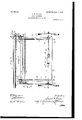
The invention will be more readily understood from the following description by reference to the accompanying drawings, forming a part of the description, and in which Figures 1 and 2 taken together constitute a view in side elevation of the entire hayloader; Figs. 3 and 4 taken together constitute a top plan view of the machine. Fig. 5 is a view, partly in section and partly in elevation, taken on line 5 5 of Fig. 1 and looking in the direction of the arrows, parts being broken out to reduce the height of the figure. Fig. 6 is a fragmentary detail, partly in side elevation and partly in vertical section, taken approximately on line 6 6 of Fig. 3 and looking in the direction of the arrows. Fig. 7 is a sectional view taken on line 7 7 of Fig. 8 is an elevation or face view of theremote side of the largest gear seen in Fig. 6. Fig. 9 is a horizontal sectional view taken on line 9 9 of Fig. 6 and looking downwardly. Fig. 10 is a fragmentary detail taken approximately on line 10 10 of Fig. 6, but including the extreme outer end of the carrier-frame and looking downwardly. Figs. 11 and 12 are front and side elevations, respectively, of one of the main carrier-sprockets located at the receiving end of the carrier and showing particularly the construction and arrangement of the pick-up fingers and coperating cam mechanism. Fig. 13 is a fragmentary plan view of the principal operative parts of the automatic hitching apparatus. Fig. 14 is a longitudinal vertical section taken on line 14 14 of Fig. 13, the part being, however, in changed position. Fig. 15 is a fragmentary cross-sectional view of the rake-head. Fig. 16 is a sectional view taken approximately on line 16 16 of Fig. 1 with parts brokenout. Fig. 17 is a sectional view taken on line 17 17 of Fig. 6. Fig. 18 is a sectional view taken on line 18 18 of Fig. 2.
Referring to the drawings, 1 designates as a- Patented Jan. 9, 1906.
whole a main wheeled supporting-frame comprising side frame members 2, front and rear cross frame members 3 and 4, respectively, (the former being shown in Fig. 13,) upright frame members 5 and 6 at each side of the machine, and diagonal brace members 7. The several frame members are conveniently formed of angle-iron and are so constructed and united as to form a rigid strong supporting-frame for the carrier mechanism. neath the forward part of the main frame is secured the main supporting-axle 8, provided with the usual supporting-wheels 9 at each end, while the rear end of the main frame is conveniently supported by means of a pair of caster-wheels 10, adjustably connected with the main frame, so that the latter may be raised or lowered, as indicated clearly at 11.
12 designates main supportingframe members, one at each side of the machine, -ar ranged to extend obliquely upwardly from the lower side frame members 2 to the extreme upper end of the inclined portion of the elevator and connected at their upper ends with corresponding horizontal side frame members 13, which latter extend forwardly and constitute the horizontal carrierframe and also extend rearwardly to and are connected with the uprights 5 at the respective sides of the machine. Both the frame members 12 and 13 are channel-shaped in cross-section, with their open sides facing in wardly for a purpose which will hereinafter appear.
Describing next the rake or gathering mechanism, 14 designates a pair of brackets mounted upon the side frame members 2 near the rear ends of the latter and provided at their upper ends with sockets 15, within which are mounted the ends of a tubular rake head or bar 16. Referring more specifically to detail Fig. 15 the spring rake-teeth 17 are shown as provided at their attached ends with the usual coils 18, which are arranged to encircle the tubular rake-head and terminate in upturned extensions 19, which extend through suitable apertures in the confining-bar 20. The confining-bar 20 is rigidly bolted to the upper side of the rake-head by means of bolts 21, arranged to extend vertically through said members at points between the raketeeth, as shown clearly in Fig. 3. In order that the rake-head and set of teeth mounted thereon may be manipulated, a hand-lever 23 is rigidly connected with each end of the tubular rake-head, one end of each lever being arranged to traverse a notched segment 22, while the opposite end is provided with the usual handle and latchhandle 24. The handle 24 is arranged to control a spring-pressed dogging-latch 25, which cooperates with the notched segment 22 in the usual manner. At a point vertically below the rake-head the side frame members 2 are provided with depending brackets 26, having journal-bearings at their lower ends within which are seated the ends of a sprocket-shaft 27, carrying adjacent to each of its ends and inside of the respective brackets sprocket-wheels 28, which are rigidly mounted thereon. The carrier or conveyer belt extends around and is carried at its lower end by the sprockets 28.
In order to assist in picking up the hay and delivering it to the upper side of the carrier as it is gathered by the rake-teeth, I provide cooperating pick-up fingers which are constructed and arranged as follows: 30 and 31 respectively designate two fingershafts which are mounted to extend between the two main sprockets 28 at diametrically opposite sides of the latter and are mounted upon and carried by said sprockets. Said finger-shafts are each provided at each end with a crank extension 32, provided with a wrist portion 33, which extends through and is journaled within a suitable bearing-aperture in the periphery of the corresponding sprocket-wheel, the wrist being provided at the outer side of the sprocket with a crankarm 34, which in turn terminates in a cam projection 35, which is preferably surrounded by an antifriction-roller 36. 37 designates a peculiarly-shaped cam-block mounted rigidly upon the supporting-bracket 26 between the latter and the corresponding sprocket, the periphery of said camblock forming an irregularly-curved path or cam-surface 38, which is adapted to cooperate with the cam projection 36 of the crank 34. The crank extensions 32 stand at obtuse angles in relation to the crank-arms 34, these relations being important in the operation of the device, as will now be explained. Each pick-up finger-shaft is provided with a series of straight rigid lingers 39, spaced at intervals apart and of a suitable length to reach rearwardly to and between the pairs of teeth of the rake as the pick-up-finger shafts are carried around during the revolution of the sprockets 28.
Assuming that the sprocket-wheels have reached the position shown in Fig. 12, the then descending pick-up-finger shaft has reached a position where gravity tends to throw the lingers 39 and shaft, upon which they are mounted, downwardly, and this movement is limited by means of a stop 40, mounted in the periphery of the sprocket and engaged by the crank-arm 34. As soon as the fingers reach the hay resting upon the ground or accumulated in advance of the rake-teeth the pressure of the hay tends to arrest or lift the ends of the pick-up fingers, and by this time the cam projection 36 will have reached a position radially opposite the cam-surface 38 of the cam-block. The camblock therefore serves to hold the fingers rigid and in approximately radial relation to the sprocket until the fingers have reached a tween the slats of the upper lap of the carrier the cam projection 36 encounters the re' curved portion 38 of the'cam, which operates to tilt the fingers forwardly again to a position where the center of gravity falls outside of the axis ofthe wrists 33, whereupon the parts resume the position shown in Fig. 12, wherein the arm 34 rests in engagement with the stop 40.
Describing now the arrangement of the carrier or conveyer belt, and referring more particularly to Figs. 1 and 2, 41 designates a cross-shaft which is journaled in suitable bearings mounted upon the under side of the horizontal frame members 13. Upon the shaft 41, at points between its ends and near the respective ends thereof, are rigidlymounted s rockets 42, which carry the sprocket-be ts of the carrier 29. Upon the same shaft 41, at one end thereof, are rigidly mounted two other sprockets 43 and 44, res ectively, one of which carries the main d five-bclt 45, while the other carries a transmission belt 46, the main belt 45 being driven from a larger sprocket 47, mounted upon the main axle 8 of the wheel-frame. Inasmuch as the shaft 41 imparts motion to all of the several drive-sprockets which actuate the carrier, said shaft will be hereinafter designated the main shaft. From the pair of sprockets 42 the carrier extends horizontally forward to and around a pair of sprockets 48, which are loosely mounted upon the shaft 49, the ends of which constitute trunnions 50, mounted in rollers 51, which are in turn confined to travel within the channels 52 of the frame members 13. From the sprockets 48 the carrier returns and passes over a pair of sprockets 53, rigidly mounted upon a shaft 54, which is j ournaled in suitable ournal-boxes 55, mounted upon the upper-sides of the respective frame members 12. From the sprockets 53 the carrier passes downwardly and around a pair of take-up sprockets 56, loosely ournaled upon a cross-shaft 57, which is exactly similar to the shaft 49 and is similarly provided at its ends with trunnions 58, engaged with rollers 59, which are confined and travel within the channels of the side frame members 12. From the sprockets 56 the carrier returns upwardly and passes around a pair of sprockets 61, rigidly mounted upon a shaft 62,which is in turn journaled in a pair of brackets 63, mounted upon the under sides of the respective frame members 12. In this connection it is to be noted that it is the shaft 62, which carries the sprocket 63, around which the transmission -belt 46, hereinbefore referred to, is trained. From the sprockets 61 the carrier extends downwardly to and around the main lower sprockets 28, hereinbefore referred to, thus completing the circuit.
From the foregoing it will be understood that the carrier is endless, and were the several supporting-sprockets mounted so as to be incapable of bodily movement the carrier would travel around the sprockets in the ordinary manner, the hay being delivered always at the extreme end of the horizontal extension. It will be further obvious that if the sprockets 53 be rotated at a greater speed than the speed of travel imparted to the upper lap of the carrier from the main shaft 41 through the sprockets 42, mounted thereon, then if the pair of sprockets at the forward end of the horizontal extension be free to move rearwardly (as they are) said outer end sprockets will be withdrawn and the surplus length of the carrier thus drawn in by the sprockets 53 will permit the pair of sprockets 56 to descend or loop back between the two main upper and lower laps of the inclined portion of the carrier. It will be further obvious that if this movement be con tinued until the extendible portion of the carrier is fully retracted, and thereupon the sprockets 53 are locked rigidly against rotation while the sprockets 61 are continued in rotation, the latter acting upon the lower lap of the looped-back portion of the carrier will return said looped-back portion to its uppermost position. If now the pair of sprockets 56 be connected by means of tension-chains 64 from the shaft 57 carrying said sprockets downwardly around guide-pulleys 65 at the lower end of the carrier, thence upwardly over guide-pulleys 66, and from there horizontally forward and around similar guides 67 lo cated at the extreme forward end of the carrier-frame, and back to and connected with the shaft, which carries the movable pair of sprockets 48, then it will be clear that as fast as the pair of sprockets 56 are drawn up wardly by the sprockets 61 the extension portion of the carrier will be positively drawn outwardly. The mechanism by means of which the carrier is thus actuated will now be described.
Referring more particularly to detail Fig. 16, the main shaft 41 is provided adjacent to one end with a loosely-mounted spur-gear 68 and immediately adjacent thereto with a co operating clutch wheel 69, also loosely mounted upon the main shaft. (See also detail Figs. 6, 7, and 8.) The clutch-wheel 69 IIO is provided with a peripheral series of notches 70, and adjacent thereto is mounted to reciprocate a vertically-movable dog 71, working through a suitable bearing 72, mounted upon the main side fi'ame member 13, The dog 71 is provided at a point coincident with the interior channeled portion of the frame member 13 with a horizontal offset portion 7 3 and also with a vertical extension 74, which extends downwardly to and projects through an opening in the upper side of the inclined frame member 12, so as to protrude within the channel of the latter. The lower end of the extension 74 terminates in a cam projection or shoe 75, which is located within the channel of the member 12 and is adapted to be acted upon by the trunnion roller 59, which carries the end of the shaft 57, as hereinbefore described. 7 6 designates a trippinglatch, mounted to reciprocate within the channeled portion of the horizontal member 13 and normally held projected by means'of a coiled spring 77, the engaging end of said latch be ing arranged to project beneath a shoulder 78, formed upon the dog 71, as shown clearly in detail, Fig. 7, in such manner as to hold the dog in its uplifted position. In order to retract the trippinglatch 76, the latter is provided with a rod-like extension 79, which extends forwardly some distance and terminates in a bumper 80, which is located in the path of the trunnion-roller 51, which carries the end of the shaft 49. In order to lock the gear 68 rigid with the main shaft upon which it is mounted, I provide upon the main shaft, adjacent to the side of said gear, a ratchet 81, (see Fig. 8,) with which ratchet is arranged to cooperate a radially-movable doggingpawl 82, mounted to reciprocate within a suitable way or bearing 83 upon the side face of the gear. The dogging-pawl is provided with a cam-stud 84, (see sectional Fig. 7,) which projects through a radial slot 85, formed in the gear 68 and engages at the opposite side of said gear an eccentrically dis posed and curved cam-slot 86, formed in the clutch-wheel 69. The relative arrangement and construction of these parts is such that when the spur-gear is rotated relatively to the clutch-wheel in one direction the dogging pawl will be withdrawn out of engagement with the ratchet 81 and when rotated in the opposite direction will be permitted to engage. Normally the gear and clutch-wheel are held in position to permit the doggingpawl to engage the ratchet by means of a spiral spring 87, the intermediate portion of which is coiled around the hub of the former, while one end is rigidly connected to the clutch-wheel, as indicated at 88, and the opposite end arranged to engage a stop-lug 89, mounted upon the gear. 90 designates a pinion loosely mounted upon the shaft 54 and arranged to intermesh with the gear 68. Adjacent to the pinion 90 is mounted an endwise-shiftable clutch 91, which is provided with the usual clutch-teeth 92, arranged to engage corresponding recesses 93, formed in the proximate face of the pinion, said clutch being splined upon the shaft 54 and being actuated by means of a bell-crank lever 94, which terminates in a yoke 95, the ends of which engage the usual annular groove 96 upon the clutch. It is to be noted that this clutch 91 is so constructed as to lock the pinion rigid against rotation upon the shaft in either direction. Inasmuch as the pinion 90 intermeshes with the gear 68, it follows that when the latter is locked against rotation, as hereinbefore described, the shaft 54, and with it the sprockets 53, mounted thereon, will be likewise locked against rotation so long as the clutch 91 remains in gear.
Normally-t. 0., during the automatic extension and retraction of the carrier-the clutch 91 will remain in engagement with the pinion 90 at all times; but when the operator desires to interrupt the automatic extension or retraction of the carrier and deliver the hay at a fixed point during a definite period of time the bell-crank lever 94 is operated to throw the clutch out of engagement with the pinion. In order to actuate the bell-crank, a chain or cable 97 is connected with the arm of the bell-crank and extends thence for- 5 wardly to a hand-lever 98, pivoted upon the outside of one of the side frame members 13. The bell-crank lever is normally held in position to hold the clutch in gear by means of the coiled contractile spring 99, connected with the lever and with a fixed support 100 on the frame member. (See detail Fig. 10.)
In order to hold the hay yieldingly in engagement with the inclined portion of the carrier during its elevation, I provide a floating frame (designated as a whole 101, see Fig. 3,) composed of a series of longitudinal slats 102, united at their upper and lower ends by suitable cross-strips 103 and 104, respectively. This frame is arrangedto rest by gravity upon the carrier or hay carried thereby and is supported in this position by means of a pair of depending links 105, pivotally connected at their upper ends to the brackets 14, as indicated at 106, and suitably connected at their lower ends to the ends of cross-strip 104.
In order to prevent the hay from being blown from the horizontal portion of the carrier, I provide a canvas wind-guard 107, which extends between the upper and lower laps of the extendible portion of the carrier and is retractable and extendible with the latter. To this end the shaft 57 is provided with a pair of radial arms 56, to which the tension-chains 64, hereinbefore described, are connected, thereby holding said shaft against rotation and in a definite position. Said shaft is also provided at each end with an upstanding radial stud 108, between the upper ends the shaft 49 conveniently by being adj ustably buckled to the latter, so that the web may be held taut, as best shown in Fig. 4. Inasmuch as the tension-chains hereinbefore referred to always keep the shafts 49 and 57 at a definite distance apart, measured lineally of the car rier, it follows that the canvas will remain taut and reciprocate with the extensible portion of the carrier.
Describing next the automatic hitch mechanism, constituting one feature of the invention, and referring more particularly to Figs. 1, 13, and 14, upon the main axle 8 of the wheeled frame is loosely mounted a sleeve 110, which is provided externally with a spline 111, upon which is arranged to reciprocate a drum 112. To the drum is attached one end of a traction-cable 113, the opposite end of which extends forwardly through a guide 114, mounted upon the ends of the hounds of the wheeled frame and terminates in an eyebar 115, adapted for attachment with a suitable stud carried by the axle of the wagon. The drum 112 is provided. at one end with an external screw-thread 116, which is engaged with a fixed block 117, mounted upon aframe member 118. At one end of the drum adjacent to the end of the sleeve 110 is mounted a clutch 118, which has splined engagement with the axle and is toothed to engage the correspondingly-toothed end of the sleeve, as indicated at 119. The clutch 118 is provided with an annular groove, which is engaged by a yoke 120, forming the free end of a lever. 121, which is pivotally connected at its opposite end, as indicated at 122, to the frame member 118 or other suitable support. 123 designates a coiled contractile spring connected at one end to the main cross-frame member 3 and at its opposite end to the lever 121 at a point intermediate the length of the latter, the relation of the spring to said lever being such that in the shifting of the clutch to one position or the other of its limits of movement the spring is carried past the dead center point of the lever-pivot, so that the clutch will be held to whichever position it is shifted. It follows that when the clutch is in engagement with the sleeve, as indicated in the drawings, the rotation of the axle will rotate the drum and, by reason of the screw-threaded engagement of the drum with the block 117, the drum will be positively shifted endwise along thesleeve toward the clutch as the traction-chain is wound up. This rotation will be continued until the end of the drum engages the clutch and positively forces the latter out of engagement with the sleeve,
thereupon permitting the sleeve, and with it the drum, to stand idle while the axle continues its rotation. The eyebar 115 is provided in its upper face witha series of ratchetnotches 115, with which notches is arranged to cooperate a gravity-pawl 124, pivoted to the upper side of the guide 114and working through an opening in thelatter. The length of the traction-chain is so adjusted that the eyebar will be drawn within the guide 114 and in position for its notches to register, or approximately register, with the pawl 124 at the time the clutch 118 is thrown out of engagement with the sleeve. It follows that as soon as the drum is disengaged from driving engagement with the axle the pawl will act to engage the eyebar, and thus positively hitch the loader to the wagon. After the loader has been unhitched from the wagon the operator simply lifts up the gravity-pawl and pulls out the traction-chain to the required extent and then manually throws the clutch 118 over into engagement with the sleeve, thus placing the mechanism in readiness for hitching on again.
Describing now the operation of the loader and assuming an initial position corresponding to that shown in the drawings, it will be seen by reference to Figs. 6, 7, and 8 that the carrier has just reached the position in which it is fully extended, the dog 71 having just been raised, so as to free the gear 68 and cooperative clutch-wheel 69. During the time the dog 71 was holding the clutchwheel locked a ainst rotation the tension of that part of t e carrier engaged with the sprockets upon the shaft 54 which carries the pinion was acting through said pinion to hold the gear 68 rotated to such position relatively to the clutch-wheel as to hold the doggingpawl 82 free from the ratchet 81. As soon, however, as the dog 71 was released the spring 87 shifted the gear and clutcl1wheel relatively to each other, thereby throwing the dogging-pawl 82 into engagement with the ratchet 81', and thus instituting a driving connection between the main shaft 41 and the pinion-shaft 54. This driving connection having been thus made, the shaft 54, and with it the sprockets mounted thereon, will be rotated at a speed much greater than the peripheral travel of the sprockets 43, mounted directly upon the main shaft. In the present instance the relation of these speeds approximately is two to one. This will of course draw that portion of the underlap of the belt which at that time constitutes the horizontal portion of the carrier rearwardly' twice as fast as the hopper-lap of the same portion of the carrier is run forwardly,which will of course positively draw rearwardly the outer set of sprockets carrying the extension end of the carrier. As these latter are drawn rearwardly the tension chains or cables will, through the connections hereinbefore dether rotation of the gear 68 will, through the action'of the cam-pin 84 engaging the eccentric slot of the clutch-wheel, withdraw the dogging-pawl 82, so that the gear 68 will be thrown out of driving engagement with the shaft upon which it is mounted and come to rest. The arresting of the gear 68 will of course hold the pinion 90 stationary and through the medium of the clutch 91 in turn hold the shaft 54 and sprockets 53 thereon stationary. Thereupon the shaft driven through the chain 46 becomes the drive-shaft of the carrier, and since the sprockets 53 are now held stationary the looped-back portion of the carrier will be taken up at a rate of speed equal to one-half the peripheral speed of the sprockets 61. During this taking-up operation the tension-chains again operate to extend the extension portion of the carrier. Notwithstanding the fact that the under lap of the horizontal portion of the carrier is at this time stationary it will be obvious that the upper lap will, in fact, be running outwardly, because the shaft carrying the outer pair of sprockets is at this time drawn for wardly by the tension chains. It will be seen, therefore, that the delivery of hay from the carrier is continuous during both the retracting and extending operation of the carrier and that these operations are alternate and automatic. If at any time the operator wishes to arrest the automatic to-and-fro movement of the carrier, he simply throws over the hand-lever 98, thereby throwing the clutch 95 out of driving engagement, whereupon the carrier will simply be operated from the main shaft 41 without any of its supporting-sprockets changing their relative positions so long as the clutch thus remains out of gear.
The peculiar operation of the pick-up fingers was fully and clearly set forth in connection with the description of the mechanism and need not be repeated. It may be noted, however, that the movement of these fingers is such as to effectively clear the rake-teeth and deliver the hay well within the range of the elevating portion of the carrier and that the fingers are withdrawn from their positions extending through the upper lap of the carrier in such manner as not to at all interfere with the progress of the material being elevated. It is to be noted also in this connection that the cross-slats of the carrier are suitably spaced apart and so adjusted upon the sprocket-chains of the carrier as to avoid interference with the revolution of the pickup fingers.
While I have herein shown and described a practical and what I deem to be a preferred embodiment of my invention, yet I do not wish to be understood as limiting myself in any sense to the'specific construction shown herein. On the contrary, the mechanism may be modified without departing from the spirit of the invention. For example, it is not necessary that a portion of the carrierbelt be actually held stationary in order to secure the automatic extending and retracting operation of the carrier but the same effect may be secured through the use of change-speed mechanism. Likewise, while the endless carrier herein shown is obviously an extremely practical and desirable construction, yet within the broader scope of'my invention I do not deem such an endless car rier essential, but, on the contrary, do not 7 limit myself to the details of construction shown and described, except to the extent that they are made the subject of specific claims.
I claim as my invention- 1. In a hay-loader, the combination with a portable frame, of an elevating-carrier, a 00- operating extendible and retractable carrier, driving connections for operating said carriers during the movement of said frame, and mechanism for automatically reversing the extending and retracting movement of said horizontal carrier during operation.
2. In a hay-loader, the combination with a portable frame, of an endless elevating and delivering carrier moving thereon, one portion thereof inclined and the other portion thereof substantially horizontal, mechanism for automatically extending and retracting the horizontal portion longitudinally, and mechanism for automatically actuating said carrier during the movement of said frame.
3. In a hay-loader, the combination with a portable frame, of an endless elevating and delivering carrier moving upon said frame, one portion thereof inclined and the other portion thereof substantially horizontal, said horizontal portion adapted to be automatically extended and retracted longitudinally during the movement of said frame and carrier, driving connections for actuating said carrier, and mechanism for automatically reversing the extending and retracting move ment of the horizontal portion of said carrier during its operation.
4. In a hay-loader, the combination with a portable frame, of an elevating-carrier, a cooperating delivery-carrier adaptedto be extended and contracted, mechanism for automatically extending and retracting said delivery-carrier during operation, driving connections for actuating said carrier, and a floating guard-frame overlying said elevatingcarrier and yieldingly retaining the hay thereupon during its upward movement.
5. In a hay-loader, the combination of a main Wheeled frame, a rake suspended therefrom, an inclined elevating-carrier frame portion, a horizontal carrier-frame portion connected with the upper part of said inclined frame portion, an endless carrier traveling upon'said inclined and horizontal frame portions, mechanism for telescoping said carrier within itself to extend and retract the delivery end thereof, and mechanism for actuating the carrier.
6. In a hay-loader, the combination with a main Wheeled frame comprising an inclined carrier-frame portion and a horizontal extension connected with the upper end thereof, of an endless carrier mounted to travel upon said frame and extension, a support for the delivery end of said carrier mounted to reciprocate longitudinally on the horizontal extension of the frame, mechanism for automatically reciprocating and reversing the move ment of said support, and mechanism for actuating said carrier.
7. In a hay-loader, the combination of a main wheeled frame comprising upwardly-inclined guides and horizontally-disposed guides at the upper ends of said inclined guides, a carrier-support at the receiving end of the carrier, a movable carrier-support mounted to reciprocate upon said horizontally-disposed guides and supporting the delivery end of the carrier, an intermediate carrier-support mounted to reciprocate upon the inclined guides, an endless carrier trained around said several supports, mechanism for holding said movable supports in various positions of adjustment, and mechanism for operating the endless carrier.
8. In a hay-loader, the combination of a main wheeled frame comprising upwardly-inclined guides and horizontally-disposed guides at the upper ends of said inclined guides, a carrier-support at the receiving end of the carrier, a movable carrier-support mounted to reciprocate upon said horizontally-disposed guides and supporting the delivery end of the carrier, an intermediate carrier-support mounted to reciprocate upon the inclined guides, an endless carrier trained around said several supports, mechanism for holding said movable supports in various positions of adjustment, mechanism for operat- .ing the endless carrier, comprising mechanism for imparting a determined rate of travel to one portion of the carrier, and mechanism for imparting a different rate of travel to another portion of the carrier, for the purpose set forth.
9. -In a hay-loader, the combination of a main wheeled frame, a rake suspended at the rear end of said frame, an inclined carrierframe extending from the rake upwardly and forwardly, a horizontal frame extension connected with the upper end of the inclined frame portions, an endless carrier supported upon said inclined and horizontal frame portions, a bodily-shiftable carrier-support mounted to reciprocate upon the horizontal frame extension and supporting the delivery end of said carrier, a take-up carrier-support movably mounted to reciprocate upon the inclined frame portion and engaging with the intermediate portion of the endless carrier, tension-cable and guide-pulley connections between said movable intermediate carriersupport and said movable delivery end carrier-support, and driving connections for actuating said carrier.
10. In a hay-loader, the combination of a main wheeled supporting-frame, a rake operatively supported from the rear end of said frame, a rotatable carrier-support located in proximity to said rake, a horizontal frame extension connected with the upper part of the main frame, rotatable carrier-supports located at or near the junction of the horizontal frame extension with the main frame but spaced apart vertically, a rotatable carriersupport shiftably mounted upon the horizontal frame extension,an endless carrier trained around said several specified supports, a pair of inclined guides located at the respective sides of the carrier and between the upper and lower laps of the inclined portions thereof, an intermediate carrier-support mounted to reciprocate bodily upon said inclined guides and around which the looped back intermediate portion of the carrier extends, driving connections from one of the main supporting-wheels to one of said carrier-supports engaged with, and supporting one of the outer laps of the endless carrier, driving connections to a carrier-support engagin I the intermediate or looped back portion 0 the carrier, and means for throwing said second driving connections out of gear, as and for the purpose set forth.
11. In a hay-loader, the combination of a wheeled main frame comprising lower horizontal side-bar members, cross-frame members connectin said side-bar members, a pair of vertical uprights at each side and spaced apart longitudinally, horizontal extension side-frame members connected with said uprights at the upper ends of the latter and extending forward freely beyond said uprights, the projecting portions of said upper horizontal side-frame members being provided with ways to constitute guides, inclined guide-frame members provided with ways, extending from the intermediate portions of the upper guide members obliquely downwardly and rearwardly to the lower horizontal frame, a rake operatively suspended from the rear end of said main frame, a lower carrier-support rotatably supported in proximity to said rake and in alinement with said inclined guide members, transversely I opposite rotatable carrier-supports located respectively above and below said inclined guides and adjacent to the junction of the guides with the upper horizontal guide members, the shaft of one of said carrier-supports constituting the main drive-shaft, an intermediate carrier-sup 'mrt mounted to reciprocate upon said inclined guides, a carrier-support mounted to reciprocate upon the horizontal guide-frame members and constituting a support for the delivery end of the carrier, an endless carrier trained around said several supports, substantially as described, driving connections from one of the supporting-wheels of the loader to said main shaft, driving connections from said main shaft to the transversely opposite carrier-support, a carrier-support engaging and supporting the lower lap of the horizontal extend ible portion of the carrier at" the juncture of said. horizontal extendible portion with. the inclined portion of the carrier, change-speed driving connections between said main shaft and the latter carriersupport, an automatically-acting mechanism for alternately throwing said change-speed mechanism into gear and locking it against rotation.
12. In a hay-loader, the combination of a wheeled main frame comprising lower hori zontal side-bar members, cross-frame mem bers connecting said side-bar members,a pair of vertical uprights at each side and spaced apart longitudinally, horizontal extension side-frame members connected with said uprights at the upper ends of the latter and extending forward freely beyond said uprights, the projecting portions of said upper horizontal side-frame members being provided with ways to constitute guides, inclined guideframe members provided with ways extending from the intermediate portions of the upper guide members obliquely downwardly and rearwardly to the lower horizontal frame, a rake operatively suspended from the rear end of said main frame, a lower carriersupport rotatably supported in proximity to said rake and in alinement with said inclined guide members, transversely opposite rotatable carrier-supports located respectively above and below said inclined guides and ad j acent to the junction of the guides with the upper horizontal guide members, the shaft of one of said carrier-supports constituting the main drive-shaft, an intermediate carriersupport mounted to reciprocate upon said inclined guides, a carrier-support mounted to reciprocate upon the horizontal guide-fra1ne members and constituting a support for the delivery end of the carrier, an endless carrier trained around said several supports, substantially as described, driving connections from one of the supporting-W1reels of the loader to said main shaft, driving connections from said main shaft to the transversely opposite carrier-support, a carriersupport engaging and supporting the lower lap of the horizontal extendible portion of the carrier at the juncture of said horizontal extendible portion with the inclined portion of the carrier, change-speed driving connections between said main shaft and the latter carrier-support, automatically-acting mechanism for alternately throwing said change-speed mechanism into gear and. locking it against rotation, and tension-cables connected with the carrier-support bodily movable on the inclined guides, extending thence around pulleys located on the lower parts of said inclined guides, thence over intermediate guides and around pulleys located at the ends of the horizontal guide-frame members and thence to and connected with the bodily-movable carrier-support traveling upon said horizontal guide-frame members.
13. In a hayloader, the combination with a portable frame provided with rake-teeth, of an elevating-carrier, a cooperating extendible and retractable carrier, mechanism for automatically operating and reversing the bodily movement of said carrier; a pair of carrier-supporting wheels located upon said frame in front of and in proximity to said rake-teeth, a plurality of rocleshafts extending between the peripheral portions of said carrier-supporting wheels, each provided with a series of radially-extending pick-up lingers, cranks upon said rock-bars provided with cam-engaging portions, and a fixed cam adjacent to the path of travel of said cranks whereby a variable movement of the rock bar is imparted during the rotation of the rock-bar-carrying wheels, substantially as described.
14. In combination with a wheeled trailerframe provided with supporting-wheels and an axle rotatable therewith, of an automatic hitching mechanism comprising a windingdrum mounted upon said axle, a traction-cable engaging said windingdrum, driving connections between the axle and the windingdrum, an automatic throw-off for disengaging said driving connections at a predetermined time, and an automatic dogging mechanism for preventing the unwinding of the cable and which is brought into action when the winding-drum is thrown out of gear.
15. In combination with a wheeled trailerframe provided with supporting-wheels and an axle rotatable therewith, of an automatic hitching mechanism comprising a windingdrum, mounted upon said axle, a traction-cable engaging said winding-drum, driving connections between the axle and the windingdrum, means for imparting a longitudinal travel of a part upon said axle proportionate to the number of revolutions of the axle, a clutch mechanism constituting a driving c011- nection between axle and the winding-drum, and operative connections between said traveling member and clutch mechanism whereby the latter is thrown out of gear at the end of a predetermined time.
16. In combination With a wheeled trailerframe provided with supporting-wheels and a shaft rotatable therewith, a sleeve rotatable upon said shaft, a clutch having splined engagement with the shaft and adapted to interengage with the sleeve to lock the latter against rotation, a Winding-drum splined upon the sleeve and provided with an external screw-thread, a fixed support with which said screw-thread is interengaged and whereby a longitudinal movement of the drum is imparted by the rotation of the latter, a traction-cable connected with the drum, and a dogging mechanism operating to automatically engage and hold the traction-cable from unwinding when the drum is released; said clutch mechanism being located in the path of travel of the drum, whereby the clutch is disengaged at the end of a predetermined number of revolutions of the drum.
SAMUEL M. WIXOEL.
Witnesses:
ALBERT H. GRAVES, FREDERICK O. GOODWIN.
Priority Applications (1)
| Application Number | Priority Date | Filing Date | Title |
|---|---|---|---|
| US15243203A US809598A (en) | 1903-04-13 | 1903-04-13 | Hay-loader. |
Applications Claiming Priority (1)
| Application Number | Priority Date | Filing Date | Title |
|---|---|---|---|
| US15243203A US809598A (en) | 1903-04-13 | 1903-04-13 | Hay-loader. |
Publications (1)
| Publication Number | Publication Date |
|---|---|
| US809598A true US809598A (en) | 1906-01-09 |
Family
ID=2878079
Family Applications (1)
| Application Number | Title | Priority Date | Filing Date |
|---|---|---|---|
| US15243203A Expired - Lifetime US809598A (en) | 1903-04-13 | 1903-04-13 | Hay-loader. |
Country Status (1)
| Country | Link |
|---|---|
| US (1) | US809598A (en) |
-
1903
- 1903-04-13 US US15243203A patent/US809598A/en not_active Expired - Lifetime
Similar Documents
| Publication | Publication Date | Title |
|---|---|---|
| US809598A (en) | Hay-loader. | |
| US778561A (en) | Conveyer. | |
| US930719A (en) | Bundle-loader. | |
| US139303A (en) | Improvement in grain rakers and loaders | |
| US358558A (en) | Loading and unloading apparatus | |
| US259427A (en) | Combined hay raker and loader | |
| US1376757A (en) | Method of and apparatus for forming stacks of grain for curing | |
| US667379A (en) | Combined hay rake and stacker. | |
| US931109A (en) | Hay-loader. | |
| US916310A (en) | Hay-loader. | |
| US1303644A (en) | Extension hay-loader | |
| US981894A (en) | Hay-loader. | |
| US159264A (en) | Improvement in hay-loaders | |
| US329687A (en) | Hay-loader | |
| US264570A (en) | Hay-loader | |
| US1056199A (en) | Grain and hay loader. | |
| US1075935A (en) | Hay-loader. | |
| US412294A (en) | Hay rake and loader | |
| US250394A (en) | Combined hay rake and elevator | |
| US596142A (en) | Hay rake and loader | |
| US256710A (en) | George w | |
| US861529A (en) | Combined hay stacker and rake. | |
| US614887A (en) | Hay-loading attachment for wagons | |
| US279647A (en) | Hay rake and loader | |
| US730879A (en) | Combined side-delivery hay and shocked-grain loader. |