US809595A - Bell push, pull, &c. - Google Patents
Bell push, pull, &c. Download PDFInfo
- Publication number
- US809595A US809595A US25832405A US1905258324A US809595A US 809595 A US809595 A US 809595A US 25832405 A US25832405 A US 25832405A US 1905258324 A US1905258324 A US 1905258324A US 809595 A US809595 A US 809595A
- Authority
- US
- United States
- Prior art keywords
- push
- disk
- bell
- pull
- insulating
- Prior art date
- Legal status (The legal status is an assumption and is not a legal conclusion. Google has not performed a legal analysis and makes no representation as to the accuracy of the status listed.)
- Expired - Lifetime
Links
- 239000000463 material Substances 0.000 description 6
- 239000011521 glass Substances 0.000 description 5
- 241000220317 Rosa Species 0.000 description 4
- 239000004020 conductor Substances 0.000 description 2
- 238000010276 construction Methods 0.000 description 2
- 210000003298 dental enamel Anatomy 0.000 description 1
- 239000005337 ground glass Substances 0.000 description 1
- 238000005286 illumination Methods 0.000 description 1
- 230000004048 modification Effects 0.000 description 1
- 238000012986 modification Methods 0.000 description 1
- 238000005192 partition Methods 0.000 description 1
- 230000000717 retained effect Effects 0.000 description 1
Images
Classifications
-
- H—ELECTRICITY
- H01—ELECTRIC ELEMENTS
- H01H—ELECTRIC SWITCHES; RELAYS; SELECTORS; EMERGENCY PROTECTIVE DEVICES
- H01H13/00—Switches having rectilinearly-movable operating part or parts adapted for pushing or pulling in one direction only, e.g. push-button switch
- H01H13/02—Details
- H01H13/023—Light-emitting indicators
Definitions
- This invention relates to improvements in and connected with bell pushes or pulls, also applicable to door-knobs and the like.
- the object of the present invention is to remove that difiiculty.
- the bellpush and the door or the like are constructed in such manner as to admit from the back of the passage of rays of light to the push or pull, and the latter is provided with a transparent or translucent front or panel which will consequently be illuminated, thus enabling the push or the like to be readily found.
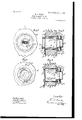
- Figure 1 is a front elevation of part of a door or the like having a bell-push applied thereto according to the present invention.
- Fig. 2 is a vertical section taken on the line 1 1 of Fig. 1.
- Fig. 3 is a similar view to Fig. 1, but with the cap removed.
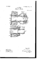
- Fig. 4 is a vertical section also taken on the line 1 1 of Fig. 1, illustrating a slight modification.
- Fig. 5 is a vertical section also taken on the line 1 1 of Fig. 1, illustrating the application of a bell-push to a door-knob.
- Fig. 6 is a similar view illustrating the application of the invention to a bellull. p
- like parts are indicated by similar letters of reference.
- a represents a portion of a door, or it might be a wall or partition, and t represents the bell-push.
- the door a is pierced with a hole or passage (1' therethrough, and fitting said passage and at each end extending beyond the same is a tube a, which at its inner end is exteriorly threaded and held in place by a nut c, which screws thereon and abuts against a rose (1.
- the front end of the tube a is also exteriorly threaded, and a threaded insulating-ring 0 screws thereon and abuts against the door a and is fixed in position by screws screwing into said door, and the insulating-ring c is also exteriorly threaded, and an apertured cap 6 screws upon said exterior thread and controls the push I), as hereinafter described.
- the inner end of the tube 0 is fitted with a disk 0 of glass, preferably ground glass, to prevent a view of the interior being obtained, or it might be a disk of other transparent or translucent material or a lens, and the front end of the push I) is similarly fitted with a disk 6", upon which is painted, engraved, or otherwise marked the word Push, and thus any light upon the opposite side of the door ja will illuminate the disk or lens I)".
- push I) is tubular and extends into the tube 0,
- the tubular push I) is provided with an annular flange 6 which is engaged by the cap 6, which incloses the working parts and limits the outward movement of the push b.
- an insulating-disk 6 against which the ends of the usual springcontacts f bear, so that no current passes to the push.
- the inner ends of the spring-contactf are fixed to the insulating-ring c and the usual conductors f are connected therewith in the well-known manner, and said conductors pass through grooves a, formed in the wall of the hole or passage a through the door, and come out beneath the rose (1 and are connected with an electric battery, in
- the interior of the tube 0 and push I) may be silvered or coated with white enamel or otherwise treated in order to reflect the rays of light passing through the same, and thus improve the illumination of the disk 6 It will be obvious that any other suitable form of contacts than those f may be employed, if desired.
- the invention is shown applied to a door-knob.
- the tube 0 is prolon ed in a forward direction and carries the insu ating-ring 0 as in the arrangement shown and described with-respect to Figs. 1 to 3; but instead of the cap a a hollow knob e is fixed with the door a, and the cap e instead of screwing onto the insulating-ring 0 screws into the front end of the knob e, while the tube 0 at its rear end terminates short of the glass disk 0, which latter is carried by the rose d, as shown and described with respect to Fig. 4; but in other details of construction the device is similar to those previously described.
- a tubular handle 6 is employed, having in the frontend thereof a glass disk or lens 6*, bearing the word Pull, and the inner end of the handle or pull is formed as a box 5 which slides upon the insulatingring 0 while the spring-contactsf are carried by the inner side of said insulating-ring and the insulating-washer b is carried by theinner end of the box 6 and thus a pull upon the handle or pull 1) makes the re planetaryd contact.
- the device is substantially the same as that shown and described with respect to Fig. 5.
- a hole or Way through the object to which the device is afiixed a tubular movable hand-operated device in alinement with said hole at the front thereof, a disk of a ma-' terial which will allow the passage of light at the front end of said tubular device, a similar disk at the near end of said hole and means actuated by said tubular device for sounding a bell, substantially as described.
- a hole or way through the object to which the device is allixed a tubular movable hand-operated device in alinement with said hole at the front thereof, a disk of a material which will allow the passage of light at the front end of said tubular device, a similar disk at the rear end of said hole, electric contacts adapted to be brought into engagement by the movement of the tubular device and means for connecting the leads of an electricbell system with said contacts, substantially as described.
- a hole or way through the object to which the device is affixed a tubular movable hand-operated device in alinement with said hole at the front thereof, a disk of a material which will allow the passage of light in the front end of said tubular device, a similar disk at the rear end of the hole or way, an insulating-ring carrying electrical contact devices adapted to be brought into engagement by the movement of the tubular device, means for connecting the leads of an electricbell system with said contacts, a screwthread upon the exterior of the insulatingring, a flange upon the tubular device, an insulating-washer upon the inner face of said flange and means for inclosing said parts while exposing the transparent ortranslucent disk of the tubular device, substantially as described.
- a hole or way through the object to which the device is afiixed a tubular pushpiece in alinement with said hole at the front thereof, a disk of a material which will allow the passage of light in the front end of said push-piece, a similar disk at the rear end of said hole or way, an insulating-ring fixed with said object and carrying electrical contact devices adapted to be brought into engagement by the movement of the pushpiece, means for connecting the leads of an electric-bell system with said contacts, a screw-thread upon the exterior of the insulating-ring, a flange upon the tubular pushpiece, an insulating washer upon the inner face of said flange and a perforated cap fitting upon the push-piece and screwing upon the insulating-ring, substantially as described. 7
- a hole or way through the object to which the device is affixed a length of tube passing through said hole, a tubular push-piece working in the front end of said tube, a disk of a material which will allow the passage of light in the front end of said pushpiece, a similar disk at the rear end of said tube, an insulating-ring screwing into the front end of the tube and carrying electrical contact devices adapted to be brought into engagement by the movement of the pushpiece, means for connecting the leads of an electric-bell system with said contacts, a screw-thread upon the exterior of the insulating-ring, a flange upon the tubular pushpiece, an insulating-washer upon the in- IIO SOQBQS Q her face of said flange and a perforated cap push and opposite end of said hole orway fitting upon the push-piece and screwing each bein furnished'with adisk of material 10 upon the insulating-ring, substantially as dewhich wil allow of the passage
Landscapes
- Push-Button Switches (AREA)
Description
PATENTED JAN. 9, 1906.
L. S. WILKS. BELL PUSH,PULL, &c.
APPLIGATION FILED MAY 1,1905.
2 SHEETSSHEET 1.
77mm W/ No. 809,595. I PATENTED JAN. 9, 1906.
L. S. WILKS.
BBLL'PUSH, PULL. 6w.
APPLICATION FILED MAYl,1905.
2 SHEETS-SHEET 2.
UNITED STATES PATENT OFFICE.
BELL PUSH, PULL, a...
Specification of Letters Patent.
Patented Jan. 9, 1906.
Application filed May 1, 1905. Serial No. 258,324.
To all whom it may concern.-
Be it known that I, LAWRENCE SOLOMON WILKs, a subject of the King of Great Britain, residing at York House, Whipps Cross, in the county of Essex, England, have invented new and useful Improvements in and Relating to Bell Pushes or Pulls, also Applicable to Door-Knobs and the Like, of which the following is a specification, reference being had to the drawings hereunto annexed and to the letters marked thereon.
This invention relates to improvements in and connected with bell pushes or pulls, also applicable to door-knobs and the like.
There is fre uently a difliculty in finding a bell-push or t e like, particularly when it is located upon the outside of a house; and the object of the present invention is to remove that difiiculty. For this purpose the bellpush and the door or the like are constructed in such manner as to admit from the back of the passage of rays of light to the push or pull, and the latter is provided with a transparent or translucent front or panel which will consequently be illuminated, thus enabling the push or the like to be readily found.
In the accompanying drawings, Figure 1 is a front elevation of part of a door or the like having a bell-push applied thereto according to the present invention. Fig. 2 is a vertical section taken on the line 1 1 of Fig. 1. Fig. 3 is a similar view to Fig. 1, but with the cap removed. Fig. 4 is a vertical section also taken on the line 1 1 of Fig. 1, illustrating a slight modification. Fig. 5 is a vertical section also taken on the line 1 1 of Fig. 1, illustrating the application of a bell-push to a door-knob. Fig. 6 is a similar view illustrating the application of the invention to a bellull. p In the several figures like parts are indicated by similar letters of reference.
Referring to Figs. 1 to 3, a represents a portion of a door, or it might be a wall or partition, and t represents the bell-push. The door a is pierced with a hole or passage (1' therethrough, and fitting said passage and at each end extending beyond the same is a tube a, which at its inner end is exteriorly threaded and held in place by a nut c, which screws thereon and abuts against a rose (1.
The front end of the tube a is also exteriorly threaded, and a threaded insulating-ring 0 screws thereon and abuts against the door a and is fixed in position by screws screwing into said door, and the insulating-ring c is also exteriorly threaded, and an apertured cap 6 screws upon said exterior thread and controls the push I), as hereinafter described. The inner end of the tube 0 is fitted with a disk 0 of glass, preferably ground glass, to prevent a view of the interior being obtained, or it might be a disk of other transparent or translucent material or a lens, and the front end of the push I) is similarly fitted with a disk 6", upon which is painted, engraved, or otherwise marked the word Push, and thus any light upon the opposite side of the door ja will illuminate the disk or lens I)". push I) is tubular and extends into the tube 0,
The
and the tube of the push is formed with a slot 1/, and the tube a is provided with a stud 0 which engages said slot and prevents the push turning, so that the word Push upon the disk 6 will always be retained in correct reading position. The tubular push I) is provided with an annular flange 6 which is engaged by the cap 6, which incloses the working parts and limits the outward movement of the push b. Upon the inner face of the flange b is fixed an insulating-disk 6 against which the ends of the usual springcontacts f bear, so that no current passes to the push. The inner ends of the spring-contactf are fixed to the insulating-ring c and the usual conductors f are connected therewith in the well-known manner, and said conductors pass through grooves a, formed in the wall of the hole or passage a through the door, and come out beneath the rose (1 and are connected with an electric battery, in
the circuit of which is placed an electric bell, as will be readily understood. The interior of the tube 0 and push I) may be silvered or coated with white enamel or otherwise treated in order to reflect the rays of light passing through the same, and thus improve the illumination of the disk 6 It will be obvious that any other suitable form of contacts than those f may be employed, if desired.
In the example given at Fig. 4 the tube a, and consequently the nut c, are dispensed with and the disk of glass 0 or the like is mounted in the rose (1; but in other respects the device is identical with that hereinbefore described with respect to Figs. 1 to 3.
In the example given at Fig. 5 the invention is shown applied to a door-knob. In this case the tube 0 is prolon ed in a forward direction and carries the insu ating-ring 0 as in the arrangement shown and described with-respect to Figs. 1 to 3; but instead of the cap a a hollow knob e is fixed with the door a, and the cap e instead of screwing onto the insulating-ring 0 screws into the front end of the knob e, while the tube 0 at its rear end terminates short of the glass disk 0, which latter is carried by the rose d, as shown and described with respect to Fig. 4; but in other details of construction the device is similar to those previously described.
In the example given at Fig. 6 the invention is shown applied to a pull instead of a push. In thiscase a tubular handle 6 is employed, having in the frontend thereof a glass disk or lens 6*, bearing the word Pull, and the inner end of the handle or pull is formed as a box 5 which slides upon the insulatingring 0 while the spring-contactsf are carried by the inner side of said insulating-ring and the insulating-washer b is carried by theinner end of the box 6 and thus a pull upon the handle or pull 1) makes the re uired contact. In other respects the device is substantially the same as that shown and described with respect to Fig. 5.
In all cases it will be understood that by employing a lens in place of the disk of glass 0 the rays of light within a room or building may be condensed and powerfully projected upon the disk If, and it will be obvious that other details of construction of the device may be considerably varied, provided'that the essence of the invention namely, provision for the passage of light to the disk b* be preserved.
By the means hereinbefore described the difficultyhitherto met with of finding a bell push or pull or a door-knob in the dark will be obviated, and the position thereof will be plainly indicated.
Having thus described my invention, what I claim, and desire to secure by Letters Patent, is
1. In means for illuminating bell-actuating devices, a hole or Way through the object to which the device is afiixed, a tubular movable hand-operated device in alinement with said hole at the front thereof, a disk of a ma-' terial which will allow the passage of light at the front end of said tubular device, a similar disk at the near end of said hole and means actuated by said tubular device for sounding a bell, substantially as described.
2. In means for illuminating bell-actuating devices, a hole or way through the object to which the device is allixed, a tubular movable hand-operated device in alinement with said hole at the front thereof, a disk of a material which will allow the passage of light at the front end of said tubular device, a similar disk at the rear end of said hole, electric contacts adapted to be brought into engagement by the movement of the tubular device and means for connecting the leads of an electricbell system with said contacts, substantially as described.
3. In means for illuminating bell-actuating devices, a hole or way through the object to which the device is affixed, a tubular movable hand-operated device in alinement with said hole at the front thereof, a disk of a material which will allow the passage of light in the front end of said tubular device, a similar disk at the rear end of the hole or way, an insulating-ring carrying electrical contact devices adapted to be brought into engagement by the movement of the tubular device, means for connecting the leads of an electricbell system with said contacts, a screwthread upon the exterior of the insulatingring, a flange upon the tubular device, an insulating-washer upon the inner face of said flange and means for inclosing said parts while exposing the transparent ortranslucent disk of the tubular device, substantially as described.
4. In means for illuminating bell-actuating devices, a hole or way through the object to which the device is afiixed, a tubular pushpiece in alinement with said hole at the front thereof, a disk of a material which will allow the passage of light in the front end of said push-piece, a similar disk at the rear end of said hole or way, an insulating-ring fixed with said object and carrying electrical contact devices adapted to be brought into engagement by the movement of the pushpiece, means for connecting the leads of an electric-bell system with said contacts, a screw-thread upon the exterior of the insulating-ring, a flange upon the tubular pushpiece, an insulating washer upon the inner face of said flange and a perforated cap fitting upon the push-piece and screwing upon the insulating-ring, substantially as described. 7
5. In means for illuminating bell-actuating devices, a hole or way through the object to which the device is affixed, a length of tube passing through said hole, a tubular push-piece working in the front end of said tube, a disk of a material which will allow the passage of light in the front end of said pushpiece, a similar disk at the rear end of said tube, an insulating-ring screwing into the front end of the tube and carrying electrical contact devices adapted to be brought into engagement by the movement of the pushpiece, means for connecting the leads of an electric-bell system with said contacts, a screw-thread upon the exterior of the insulating-ring, a flange upon the tubular pushpiece, an insulating-washer upon the in- IIO SOQBQS Q her face of said flange and a perforated cap push and opposite end of said hole orway fitting upon the push-piece and screwing each bein furnished'with adisk of material 10 upon the insulating-ring, substantially as dewhich wil allow of the passage of light, subscribed. stantially as described.
5 6. In ineans for illuminating bell-actuat- LAWRENCE SOLOMON WILKS.
ing devices,. a.tubular push-piece arranged Witnesses: within one end of a hole or way through the GEO. G. NAUGHANS,
object to which the device is attached, said WALTER J. SKERTEN.
Priority Applications (1)
| Application Number | Priority Date | Filing Date | Title |
|---|---|---|---|
| US25832405A US809595A (en) | 1905-05-01 | 1905-05-01 | Bell push, pull, &c. |
Applications Claiming Priority (1)
| Application Number | Priority Date | Filing Date | Title |
|---|---|---|---|
| US25832405A US809595A (en) | 1905-05-01 | 1905-05-01 | Bell push, pull, &c. |
Publications (1)
| Publication Number | Publication Date |
|---|---|
| US809595A true US809595A (en) | 1906-01-09 |
Family
ID=2878076
Family Applications (1)
| Application Number | Title | Priority Date | Filing Date |
|---|---|---|---|
| US25832405A Expired - Lifetime US809595A (en) | 1905-05-01 | 1905-05-01 | Bell push, pull, &c. |
Country Status (1)
| Country | Link |
|---|---|
| US (1) | US809595A (en) |
Cited By (2)
| Publication number | Priority date | Publication date | Assignee | Title |
|---|---|---|---|---|
| US2546086A (en) * | 1945-11-03 | 1951-03-20 | Wilhelm W Brockway | Plate push button |
| USD689828S1 (en) * | 2010-10-25 | 2013-09-17 | Theodore Pierson | Doorbell button |
-
1905
- 1905-05-01 US US25832405A patent/US809595A/en not_active Expired - Lifetime
Cited By (2)
| Publication number | Priority date | Publication date | Assignee | Title |
|---|---|---|---|---|
| US2546086A (en) * | 1945-11-03 | 1951-03-20 | Wilhelm W Brockway | Plate push button |
| USD689828S1 (en) * | 2010-10-25 | 2013-09-17 | Theodore Pierson | Doorbell button |
Similar Documents
| Publication | Publication Date | Title |
|---|---|---|
| US3719821A (en) | Illuminated attachment for a lock-equipped door knob | |
| US809595A (en) | Bell push, pull, &c. | |
| US6036330A (en) | Light switch extender | |
| US2546086A (en) | Plate push button | |
| US2252829A (en) | Switch plate | |
| US1985483A (en) | Combined doorknob and lighting device | |
| US2221505A (en) | Combined adapter and reflector for lamps | |
| US598033A (en) | Electric signaling device | |
| US3479498A (en) | Automatic closet light | |
| US2991337A (en) | Master selector switch | |
| US1149973A (en) | Annunciator-fixture for residences. | |
| US1248384A (en) | Electric wall-switch. | |
| US2498943A (en) | Illuminated switch socket | |
| US2767498A (en) | Illuminated switch | |
| US994867A (en) | Electrical advertising device. | |
| US1931310A (en) | Indicating device for switches | |
| US3168730A (en) | Door knob contained electric signal structure | |
| US4615254A (en) | Organ drawknob | |
| US296812A (en) | Selwyn | |
| US374036A (en) | Circuit-closer | |
| US3244820A (en) | Sealed rotary switch having fixed supports | |
| US3363069A (en) | Decoder switch for coded electric circuits | |
| US970698A (en) | Keyhole-illuminating device. | |
| US501450A (en) | Sylvania | |
| US685614A (en) | Support for electric push-buttons. |