US80957A - ho eton - Google Patents
ho eton Download PDFInfo
- Publication number
- US80957A US80957A US80957DA US80957A US 80957 A US80957 A US 80957A US 80957D A US80957D A US 80957DA US 80957 A US80957 A US 80957A
- Authority
- US
- United States
- Prior art keywords
- buckets
- well
- water
- crab
- wheel
- Prior art date
- Legal status (The legal status is an assumption and is not a legal conclusion. Google has not performed a legal analysis and makes no representation as to the accuracy of the status listed.)
- Expired - Lifetime
Links
Images
Classifications
-
- F—MECHANICAL ENGINEERING; LIGHTING; HEATING; WEAPONS; BLASTING
- F04—POSITIVE - DISPLACEMENT MACHINES FOR LIQUIDS; PUMPS FOR LIQUIDS OR ELASTIC FLUIDS
- F04B—POSITIVE-DISPLACEMENT MACHINES FOR LIQUIDS; PUMPS
- F04B19/00—Machines or pumps having pertinent characteristics not provided for in, or of interest apart from, groups F04B1/00 - F04B17/00
- F04B19/08—Scoop devices
- F04B19/14—Scoop devices of endless-chain type, e.g. with the chains carrying pistons co-operating with open-ended cylinders
Definitions
- the object of this invention is to raise water from wells, without the use of any tubing orpnnip-log what ever, and by means of a cheap and simple arrangement of buckets coupled together in a continuous chain, and drawn up by passing over a revolving wheel at the top of the well.
- the chief featuresof the invention of this apparatus relate, firstly, to the formation ofthe bucketsthcmselves, and secondly, to the crab, sunken at the bottom of the well, for the purpose of tightening and guiding the chain o'f buckets.
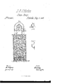
- Figure I of the drawings is a sectional elevation of a well provided with the improved device for drawing water:
- Figure 2 is a front elevation of the upper or'actuating-wheel.
- Figure 3 is an enlarged sectional elevation of the bucket.
- the buckets A- should be constructed of some non-corrosive metal, and have an inclined bottom, near the lower corner of which an aperture, a, will permit the water in the buckets to be discharged down into the well, andthus avoid freezing the water in the buckets in the winter-time.
- the buckets A are to be connected together in a continuous line, by means of the short chains a', which connect the bottom of onc'buc'ket'n'ith the top of the next.
- the chain of buckets thus completed, it will be drawn tightly around the two wheels C C', the wheel C being placed on top of the platform at the top of the well, and turned around on its axis by the operator, so as to set the buckets in motion when the water is to be raised.
- the wheel C' is to have its bearings in the metallic crab B, which is to be sunken at the bottom of the well.
- the wheels C O are formed of two annular rims, connected together by transverse rods c, which are placed at suchl distances apart as to allow the chains a to fall on the said rods as the wheel is revolved, thereby avoiding injury to thc'buckets by bending them over the rods as they pass around the wheels.
- -Tlie crab ⁇ 13 constitutes one principal feature of this invention, and by its usev this form of water-drawer may be introduced into any well without the necessity of a person descending into the well to adjust or arrange the bottom of the pump, as has to be 'done inputting down allqkinds of tube or chain-pumps.
- This crab may be. a semicircular trough, constructed of som'e' non-corrosive sheet metal, and arranged to furnish bearings for the lower wheel C', which will set down intothe said trough.
- This crab will have short legs Z1 at its bottom, which will settle down into the lground, at thevbottom otthe well, land hold.
- the device irmly in place, thus furnishing a substantial and firm footing for the bottom -ond of the drawer, without necessitating thc descent of a person into the-well for that purpose, as the chain of buckets may be placed around thc lower wheel, and the whole apparatus lowered down into Ythe well in that manner.
- the curb D which covers the well, has an 'inclined floor, d, on to which the buckets empty the water, as they turn over the upper wheel, and from this inclined iloor the water is discharged through the spout cl3.
- a gate, clinay be used to close the aperture to the spout, when the weather isso cold as to freeze inside of the curbing.
- the crab B when provided with short 1e as described and shown.
Landscapes
- Engineering & Computer Science (AREA)
- Mechanical Engineering (AREA)
- General Engineering & Computer Science (AREA)
- Hydraulic Turbines (AREA)
Description
@einen ttttts @anni @ffice Letters .Patent No. 80,957, elated August 11, 1868.
lIMPROVEISEII'I IN WATER-ELEVATORS.
eige Sunbelt munt tu in these ttltets what mit limiting tart et ttt samt.
TO AIL WHOM IT MAY CONCERN:
Be it known that I, J'. G. C. HOMON, of Gillespie, in the county of Macoupin, and State of Illinois,` have made certain new and useful Improvements in Water-Drawers; and I do hereby declare that the following is a full and clear description thereof, reference being had to the accompanying drawings, and to the letters of reference marked thereon.
The object of this invention is to raise water from wells, without the use of any tubing orpnnip-log what ever, and by means of a cheap and simple arrangement of buckets coupled together in a continuous chain, and drawn up by passing over a revolving wheel at the top of the well.
The chief featuresof the invention of this apparatus relate, firstly, to the formation ofthe bucketsthcmselves, and secondly, to the crab, sunken at the bottom of the well, for the purpose of tightening and guiding the chain o'f buckets.
To enable those skilled in the art to make and use my improved water-drawer, I will proceed to describe its construction and operation.
Figure I of the drawings is a sectional elevation of a well provided with the improved device for drawing water:
Figure 2 is a front elevation of the upper or'actuating-wheel.
Figure 3 is an enlarged sectional elevation of the bucket.
The buckets A- should be constructed of some non-corrosive metal, and have an inclined bottom, near the lower corner of which an aperture, a, will permit the water in the buckets to be discharged down into the well, andthus avoid freezing the water in the buckets in the winter-time.
The buckets A are to be connected together in a continuous line, by means of the short chains a', which connect the bottom of onc'buc'ket'n'ith the top of the next. The chain of buckets thus completed, it will be drawn tightly around the two wheels C C', the wheel C being placed on top of the platform at the top of the well, and turned around on its axis by the operator, so as to set the buckets in motion when the water is to be raised. The wheel C' is to have its bearings in the metallic crab B, which is to be sunken at the bottom of the well. A Y
The wheels C O are formed of two annular rims, connected together by transverse rods c, which are placed at suchl distances apart as to allow the chains a to fall on the said rods as the wheel is revolved, thereby avoiding injury to thc'buckets by bending them over the rods as they pass around the wheels.
-Tlie crab `13 constitutes one principal feature of this invention, and by its usev this form of water-drawer may be introduced into any well without the necessity of a person descending into the well to adjust or arrange the bottom of the pump, as has to be 'done inputting down allqkinds of tube or chain-pumps. This crab may be. a semicircular trough, constructed of som'e' non-corrosive sheet metal, and arranged to furnish bearings for the lower wheel C', which will set down intothe said trough. This crab will have short legs Z1 at its bottom, which will settle down into the lground, at thevbottom otthe well, land hold. the device irmly in place, thus furnishing a substantial and firm footing for the bottom -ond of the drawer, without necessitating thc descent of a person into the-well for that purpose, as the chain of buckets may be placed around thc lower wheel, and the whole apparatus lowered down into Ythe well in that manner.
There are numerous perforations, b', in the sides of the trough part of the crab, for the admission of the wat-cr to the buckets.
The curb D, which covers the well, has an 'inclined floor, d, on to which the buckets empty the water, as they turn over the upper wheel, and from this inclined iloor the water is discharged through the spout cl3.
A gate, clinay be used to close the aperture to the spout, when the weather isso cold as to freeze inside of the curbing.
An aperture, d1, in the floor d, near its lower side, will permit the water on the floor, after the gate cl2 is shut down,to drain back into the well. I
Having described -my invention, )vhat I claim, is-
1. The endless chain of buckets A a', and the stationery'crab B, when combined and arranged as described, and for the purpose set forth.
2. The crab B, when provided with short 1e as described and shown.
' In testimonyy of which invention, I hereunto set my hand in presence of- J.- G.v C. HORTON. Witnesses:
M. RANDOLPH, GEO. P. HER'rnnL, Jr.
gs bnndside apertures and otherwise constructed and arranged
Publications (1)
| Publication Number | Publication Date |
|---|---|
| US80957A true US80957A (en) | 1868-08-11 |
Family
ID=2150451
Family Applications (1)
| Application Number | Title | Priority Date | Filing Date |
|---|---|---|---|
| US80957D Expired - Lifetime US80957A (en) | ho eton |
Country Status (1)
| Country | Link |
|---|---|
| US (1) | US80957A (en) |
-
0
- US US80957D patent/US80957A/en not_active Expired - Lifetime
Similar Documents
| Publication | Publication Date | Title |
|---|---|---|
| US80957A (en) | ho eton | |
| US2267705A (en) | Oil field apparatus | |
| US1975953A (en) | Gate | |
| US80445A (en) | Improvement in elevator | |
| US411083A (en) | Farm-gate | |
| US184415A (en) | Improvement in guides for building ricks and stacks | |
| US64336A (en) | Improvement in deeeioks | |
| US591687A (en) | Pettit | |
| US1206790A (en) | Portable irrigating-machine. | |
| US387759A (en) | Well-curb | |
| US571993A (en) | Horse-power pu m ping-m achin e | |
| US133208A (en) | Improvement in water-elevators | |
| US388261A (en) | Automatic water-elevator | |
| US1132821A (en) | Railroad-crossing gate. | |
| US89676A (en) | Improved ditching-machine | |
| US386154A (en) | Bridge-gate | |
| US320929A (en) | Swinging gate | |
| US500032A (en) | osborn | |
| US140458A (en) | Improvement in inclined ways for building levees | |
| US77949A (en) | Emory barnes | |
| US82064A (en) | Improvement in stock-pumps | |
| US77142A (en) | weikioh and john smith | |
| US400611A (en) | Thomas tyson | |
| US76190A (en) | Improvement in gates | |
| US1055264A (en) | Well-lining. |