US809559A - Crate for transporting poultry. - Google Patents
Crate for transporting poultry. Download PDFInfo
- Publication number
- US809559A US809559A US25396305A US1905253963A US809559A US 809559 A US809559 A US 809559A US 25396305 A US25396305 A US 25396305A US 1905253963 A US1905253963 A US 1905253963A US 809559 A US809559 A US 809559A
- Authority
- US
- United States
- Prior art keywords
- sills
- wires
- secured
- crate
- cage
- Prior art date
- Legal status (The legal status is an assumption and is not a legal conclusion. Google has not performed a legal analysis and makes no representation as to the accuracy of the status listed.)
- Expired - Lifetime
Links
- 244000144977 poultry Species 0.000 title description 7
- XEEYBQQBJWHFJM-UHFFFAOYSA-N iron Substances [Fe] XEEYBQQBJWHFJM-UHFFFAOYSA-N 0.000 description 8
- 229910000746 Structural steel Inorganic materials 0.000 description 6
- 229910052742 iron Inorganic materials 0.000 description 6
- 238000000034 method Methods 0.000 description 5
- 239000002023 wood Substances 0.000 description 4
- 238000012856 packing Methods 0.000 description 2
- 238000007596 consolidation process Methods 0.000 description 1
- 238000010276 construction Methods 0.000 description 1
- VKYKSIONXSXAKP-UHFFFAOYSA-N hexamethylenetetramine Chemical compound C1N(C2)CN3CN1CN2C3 VKYKSIONXSXAKP-UHFFFAOYSA-N 0.000 description 1
- 238000012986 modification Methods 0.000 description 1
- 230000004048 modification Effects 0.000 description 1
- 230000000284 resting effect Effects 0.000 description 1
Images

Classifications
-
- B—PERFORMING OPERATIONS; TRANSPORTING
- B65—CONVEYING; PACKING; STORING; HANDLING THIN OR FILAMENTARY MATERIAL
- B65D—CONTAINERS FOR STORAGE OR TRANSPORT OF ARTICLES OR MATERIALS, e.g. BAGS, BARRELS, BOTTLES, BOXES, CANS, CARTONS, CRATES, DRUMS, JARS, TANKS, HOPPERS, FORWARDING CONTAINERS; ACCESSORIES, CLOSURES, OR FITTINGS THEREFOR; PACKAGING ELEMENTS; PACKAGES
- B65D7/00—Containers having bodies formed by interconnecting or uniting two or more rigid, or substantially rigid, components made wholly or mainly of metal
- B65D7/12—Containers having bodies formed by interconnecting or uniting two or more rigid, or substantially rigid, components made wholly or mainly of metal characterised by wall construction or by connections between walls
- B65D7/14—Containers having bodies formed by interconnecting or uniting two or more rigid, or substantially rigid, components made wholly or mainly of metal characterised by wall construction or by connections between walls of skeleton or like apertured construction, e.g. baskets or carriers formed of wire mesh, of interconnected bands, bars, or rods, or of perforated sheet metal
- B65D7/20—Containers having bodies formed by interconnecting or uniting two or more rigid, or substantially rigid, components made wholly or mainly of metal characterised by wall construction or by connections between walls of skeleton or like apertured construction, e.g. baskets or carriers formed of wire mesh, of interconnected bands, bars, or rods, or of perforated sheet metal made of wire
Definitions
- My invention relates to improvements in coops or crates for transporting poultry by railway and other means, and is so constructed as to embody the nesting orclose-packing principle for the purpose of consolidation and convenience in shipping the coops when empty, and they consist of a wire cage having sills to which the wires are attached, the said coops being provided with sliding removable bottoms, the cage-wires extending from the sills upward, having a converging inclination, and are bound by horizontal ribs which may be Welded or clamped at the enter-sections of said wires, a suitable door being provided either in the side, end, or top of the said coops, all of which will hereinafter be more fully described.
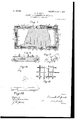
- FIG. 1 is a perspective view of a complete transportation poultry-coop embodying the elements of my invention.
- Fig. 2 is a sectional side elevation of the front sill, disclosing the method of securing the wires thereto, in which wood is used for the body of the sills.
- Fig. 3 is an end elevation with the bottom or floor in place where strap-iron is substituted for the wood sill.
- Fig. 4 is a modification of Fig. 3.
- Fig. 5 is a sectional elevation of the inner portion of the sill, showing its construction.
- Fig. 1 is a perspective view of a complete transportation poultry-coop embodying the elements of my invention.
- Fig. 2 is a sectional side elevation of the front sill, disclosing the method of securing the wires thereto, in which wood is used for the body of the sills.
- Fig. 3 is an end elevation with the bottom or floor in place where strap-iron is substituted for the wood sill.
- Fig. 4 is
- Fig. 6 is a perspective view of the angle-iron constituting the' body portion of the main sills.
- Fig. 7 is a plan view of the base-framework, the cage portion being removed and a section of the floor or bottom in place.
- Fig. Si s a right end elevation of the coop with the cage-wires broken away and the coop-bottom in place.
- Fig. 9 is a perspective view in section of a portion of the right corner of the coop, showing the bottom-locking device.
- Fig. 10 is an end elevation of the angle-iron constituting the left end and side sills of the coop.
- Fig. 11 is a view in elevation, illustrating the various line as of Fig. 2.
- Fig. 12 is a plan view of a piece of angle-iron forming the body of the main sills and illustrating the method of formin a corner.
- A represents the outer portion of the side and left end sills of the coop.
- A is the right end sill.
- the outer vertical surfaces are provided with both longitudinal and vertical grooves for the reception of the cage-wires a, having stirrup-like feet, the said wires, togetherwith the rib-wires a, constituting the cage-like body of the coop.
- the longitudinal groove Cand the vertical grooves are of suflicient depth to leave the outer surfaces of said wires a flush with the wood and are secured in place by nailing or riveting the e member of a strip of angle (or similar) iron to the outer side of the sills, covering or nearly covering and extending below the sills to provide a rest for the sliding floor or bottom B of the coop by having the member e extend inwardly. (See Figs. 3, 4, and 8.)
- the woodsill' may be substituted by strapiron A, as shown in Figs. 4 and 5, in which the rivets r, securing the strap-iron to the angle-iron, are placed in such position or location as to secure firmly in place the stirruplike feet of the Wires a.
- the first and last wires a have feet bent at a right angle to the To provide for the nesting or close packing one within another of the empty coops or crates, the wires a, extending upward from the sills, converge toward a common center and deviate from the perpendicular at any desired angle, as shown in Fig. 4 and by the dotted lines in Fig.
- the said empty coops may by removing the bottoms or floors thereupon be thus packed for the purpose of economizing space in shipment, and the bottoms or floors may be baled.
- the right-hand end sill A is narrower (vertically) than the side and left end sills A, (see Fig.
- Fig. 7 the method of securing the right end sill A in place is illustrated, in which the bar of iron forming the body of the sill has each end extended and the flange 0 cut away a suflicient distance to permit the member 6 being bent at right angles, lapping over and being secured to the right end of the sills A by rivets g g, and for the purpose of securing additional firmness the extended portion'of the strap-iron A is bent at right angles inwardly and secured in place by rivets g.
- the boards composing the floor or bottom B may be held together by staples h h or more firmly secured by cleats k 7c, Figs. 3 and 4.
- Fig. 12 The method of forming corners of angleiron is illustrated in Fig. 12, in which a portion of the member a is cut away at a cornerpoint at an angle of forty-five degrees, permitting (when raised to a proper temperature) the end z to bend to the position shown by the dotted lines.
- the upwardly-extending cage-wires a are secured in their position by being encompassed by horizontal rib-wires a and are secured at their intersections by being welded or by the use of clamps of any convenient form, as illustrated in Fig. 11, and the wires may be uniform or woven.
- the rivets 1" are for the purpose of securing greater firmness and security to the position of the strap-iron A.
- the door of the coop when closed is secured in position by the wire latch 11, loosely attached to one of the ribs 0, and passing back of wire a and in front of and extending past the extreme wire of the door or by any other convenient means.
- the bottoms or floors B of the coops are removed and the cage portions are pressed one within another and secured in position and the bottoms orfloors are baled or packed together and secured by ropes, wires, or otherwise and are thus shipped to their destination, at which point the bottoms and cage portions are unpacked, the bottoms or floors placed in position and secured therein by the locking-pins previously referred to at which time they are ready to be filled with poultry and shipped.
- a crate for transporting poultry comprising an upper part or cage, formed of upwardly and inwardly inclined wire loops, having their feet removably secured in the sills, and a divisional and sectional base, whereby the respective parts may be detached, collected and shipped in separate packages, substantially as described.
Landscapes
- Engineering & Computer Science (AREA)
- Mechanical Engineering (AREA)
- Package Frames And Binding Bands (AREA)
Description
PATENTED JAN. 9, 1906.
P. M. GAULT.
CRATE FOR TRANSPORTING POULTRY.
APPLICATION FILED APB-.5, 1905.
2 SHEBTB-SHBET 1.
2 SHEETS-SHEET 2.
PATENTED JAN. 9, 1906.
P. M. GAULT. CRATE FOR TRANSPORTING POULTRY.
APPLICATION FILED APR 5, 1905.
swan/l1 P i EM UNITED STATES PATENT OFFICE.
FRANK M. GAULT, OF OKLAHOMA, OKLAHOMA TERRITORY.
CRATE FOR TRANSPORTING POULTRY.
Specification of Letters Patent.
Patented Jan. 9, 1906.
Application filed April 5, 1905. $erial No. 258.963.
T0 aZZ whom it may concern.-
Be it. known that I, FRANKM. GAULT, a citizen of the United States, residing at Oklahoma, in the county of Oklahoma and Territory of Oklahoma, have invented new and useful Improvements in Crates for Transporting Poultry, of which the following is a specification.
My invention relates to improvements in coops or crates for transporting poultry by railway and other means, and is so constructed as to embody the nesting orclose-packing principle for the purpose of consolidation and convenience in shipping the coops when empty, and they consist of a wire cage having sills to which the wires are attached, the said coops being provided with sliding removable bottoms, the cage-wires extending from the sills upward, having a converging inclination, and are bound by horizontal ribs which may be Welded or clamped at the enter-sections of said wires, a suitable door being provided either in the side, end, or top of the said coops, all of which will hereinafter be more fully described.
The objects of my invention are to provide a light, strong, convenient coop or crate for the transportation of poultry. I attain these objects by the mechanism illustrated in the accompanying drawings, forming a part of this specification, in which Figure 1 is a perspective view of a complete transportation poultry-coop embodying the elements of my invention. Fig. 2 is a sectional side elevation of the front sill, disclosing the method of securing the wires thereto, in which wood is used for the body of the sills. Fig. 3 is an end elevation with the bottom or floor in place where strap-iron is substituted for the wood sill. Fig. 4 is a modification of Fig. 3. Fig. 5 is a sectional elevation of the inner portion of the sill, showing its construction. Fig. 6 is a perspective view of the angle-iron constituting the' body portion of the main sills. Fig. 7 is a plan view of the base-framework, the cage portion being removed and a section of the floor or bottom in place. Fig. Sis a right end elevation of the coop with the cage-wires broken away and the coop-bottom in place. Fig. 9 is a perspective view in section of a portion of the right corner of the coop, showing the bottom-locking device. Fig. 10 is an end elevation of the angle-iron constituting the left end and side sills of the coop. Fig. 11 is a view in elevation, illustrating the various line as of Fig. 2.
methods of placing and holding in place the wires composing the cage portion of the coop. Fig. 12 is a plan view of a piece of angle-iron forming the body of the main sills and illustrating the method of formin a corner.
Similar letters refer to simi ar parts in the several views.
In the drawings, A represents the outer portion of the side and left end sills of the coop. A is the right end sill. When wood is used for the base of the sills, the outer vertical surfaces are provided with both longitudinal and vertical grooves for the reception of the cage-wires a, having stirrup-like feet, the said wires, togetherwith the rib-wires a, constituting the cage-like body of the coop. (See Fig. 2.) The longitudinal groove Cand the vertical grooves are of suflicient depth to leave the outer surfaces of said wires a flush with the wood and are secured in place by nailing or riveting the e member of a strip of angle (or similar) iron to the outer side of the sills, covering or nearly covering and extending below the sills to provide a rest for the sliding floor or bottom B of the coop by having the member e extend inwardly. (See Figs. 3, 4, and 8.)
The woodsill'may be substituted by strapiron A, as shown in Figs. 4 and 5, in which the rivets r, securing the strap-iron to the angle-iron, are placed in such position or location as to secure firmly in place the stirruplike feet of the Wires a. The first and last wires a have feet bent at a right angle to the To provide for the nesting or close packing one within another of the empty coops or crates, the wires a, extending upward from the sills, converge toward a common center and deviate from the perpendicular at any desired angle, as shown in Fig. 4 and by the dotted lines in Fig. 3, that the said empty coops may by removing the bottoms or floors thereupon be thus packed for the purpose of economizing space in shipment, and the bottoms or floors may be baled. In order to provide for a removable bottom or floor, the right-hand end sill A is narrower (vertically) than the side and left end sills A, (see Fig. 8,) thus providing space for the bottom or floor B to slide into place, it resting on the horizontal members 6 of the angle-iron constituting the body of the sills, the said bottom or floor B being secured from accidental removal by the longitudinal springs d d, secured at any convenient point to the outer surface of the sills A by rivets d, the opposite ends of said springs being provided with lateral horizontal pins (1, which pass through openings in the sills and enter apertures adapted thereto in the edges ofthe bottom orfloorB. (See Figs. 7,- 8, and 9.)
In Fig. 7 the method of securing the right end sill A in place is illustrated, in which the bar of iron forming the body of the sill has each end extended and the flange 0 cut away a suflicient distance to permit the member 6 being bent at right angles, lapping over and being secured to the right end of the sills A by rivets g g, and for the purpose of securing additional firmness the extended portion'of the strap-iron A is bent at right angles inwardly and secured in place by rivets g. (See Fig. 7.) The boards composing the floor or bottom B may be held together by staples h h or more firmly secured by cleats k 7c, Figs. 3 and 4.
The method of forming corners of angleiron is illustrated in Fig. 12, in which a portion of the member a is cut away at a cornerpoint at an angle of forty-five degrees, permitting (when raised to a proper temperature) the end z to bend to the position shown by the dotted lines.
The upwardly-extending cage-wires a are secured in their position by being encompassed by horizontal rib-wires a and are secured at their intersections by being welded or by the use of clamps of any convenient form, as illustrated in Fig. 11, and the wires may be uniform or woven.
The rivets 1" are for the purpose of securing greater firmness and security to the position of the strap-iron A.
The door of the coop when closed is secured in position by the wire latch 11, loosely attached to one of the ribs 0, and passing back of wire a and in front of and extending past the extreme wire of the door or by any other convenient means.
In operation the bottoms or floors B of the coops are removed and the cage portions are pressed one within another and secured in position and the bottoms orfloors are baled or packed together and secured by ropes, wires, or otherwise and are thus shipped to their destination, at which point the bottoms and cage portions are unpacked, the bottoms or floors placed in position and secured therein by the locking-pins previously referred to at which time they are ready to be filled with poultry and shipped.
Having thus described my invention, what I claim to be new and useful, and desire to secure by Letters Patent, is- 1. A crate for transporting poultry, comprising an upper part or cage, formed of upwardly and inwardly inclined wire loops, having their feet removably secured in the sills, and a divisional and sectional base, whereby the respective parts may be detached, collected and shipped in separate packages, substantially as described.
2. In a crate for transporting poultry, the
combination with a divisional and sectional base, comprising the detachable sills A A, the removable floor-pieces B, provided with staples h h, of an inwardly-tapering cage formed of wire loops a encircled with ribwires a and provided with a suitable door substantially as described. 1 3. In a transportation poultry-coop consisting of a tapering cage portion, its base being secured to sills providing a supportingseat for the sliding removable bottom; the locking-pins d d secured in the ends of the longitudinal springs d, the said springs being firmly secured to the outer surface of the side sills, substantially as described and for the purposes set forth.
In testimony whereof I aflix my signature in presence of two subscribing witnesses.
FRANK M. GAULT.
Witnesses:
W. T. HANSON, J. R. JoNEs.
Priority Applications (1)
| Application Number | Priority Date | Filing Date | Title |
|---|---|---|---|
| US25396305A US809559A (en) | 1905-04-05 | 1905-04-05 | Crate for transporting poultry. |
Applications Claiming Priority (1)
| Application Number | Priority Date | Filing Date | Title |
|---|---|---|---|
| US25396305A US809559A (en) | 1905-04-05 | 1905-04-05 | Crate for transporting poultry. |
Publications (1)
| Publication Number | Publication Date |
|---|---|
| US809559A true US809559A (en) | 1906-01-09 |
Family
ID=2878040
Family Applications (1)
| Application Number | Title | Priority Date | Filing Date |
|---|---|---|---|
| US25396305A Expired - Lifetime US809559A (en) | 1905-04-05 | 1905-04-05 | Crate for transporting poultry. |
Country Status (1)
| Country | Link |
|---|---|
| US (1) | US809559A (en) |
Cited By (14)
| Publication number | Priority date | Publication date | Assignee | Title |
|---|---|---|---|---|
| US3208456A (en) * | 1961-10-06 | 1965-09-28 | Peebles David Meade | Supporting means for suspension files and the like |
| USD376874S (en) | 1995-04-27 | 1996-12-24 | Reyes Iii Ricardo C | Wire bird cage |
| USD377546S (en) * | 1995-01-10 | 1997-01-21 | Richard King | Bird cage top |
| US5603288A (en) * | 1995-04-28 | 1997-02-18 | Prima International Llc | Restraint device |
| USD386833S (en) * | 1994-12-15 | 1997-11-25 | Richard King | Bird cage top |
| US6244220B1 (en) * | 1999-05-24 | 2001-06-12 | Robert W. Dawson | Pyramid cage |
| USD465070S1 (en) | 2001-05-17 | 2002-10-29 | Yang Weiping | Bird cage |
| USD465619S1 (en) | 2001-05-17 | 2002-11-12 | Yang Weiping | Panel of a bird cage |
| USD467043S1 (en) | 2001-05-17 | 2002-12-10 | Yang Weiping | Bird cage top |
| USD468488S1 (en) | 2001-05-17 | 2003-01-07 | Yang Weiping | Bird cage |
| US20110076937A1 (en) * | 2009-09-25 | 2011-03-31 | Greenberg Nathan | Universal bird guard for vents |
| USD720503S1 (en) * | 2013-05-22 | 2014-12-30 | Michael Lloyd | Pet bath and carrier |
| USD804745S1 (en) * | 2016-02-20 | 2017-12-05 | Lauren Cooper | Animal waste purse |
| USD862883S1 (en) * | 2017-04-25 | 2019-10-15 | Interdesign, Inc. | Basket |
-
1905
- 1905-04-05 US US25396305A patent/US809559A/en not_active Expired - Lifetime
Cited By (16)
| Publication number | Priority date | Publication date | Assignee | Title |
|---|---|---|---|---|
| US3208456A (en) * | 1961-10-06 | 1965-09-28 | Peebles David Meade | Supporting means for suspension files and the like |
| USD386833S (en) * | 1994-12-15 | 1997-11-25 | Richard King | Bird cage top |
| USD377546S (en) * | 1995-01-10 | 1997-01-21 | Richard King | Bird cage top |
| USD376874S (en) | 1995-04-27 | 1996-12-24 | Reyes Iii Ricardo C | Wire bird cage |
| US5603288A (en) * | 1995-04-28 | 1997-02-18 | Prima International Llc | Restraint device |
| WO1998001026A1 (en) * | 1995-04-28 | 1998-01-15 | Ferber Dennis A | Restraint device |
| US6244220B1 (en) * | 1999-05-24 | 2001-06-12 | Robert W. Dawson | Pyramid cage |
| USD465619S1 (en) | 2001-05-17 | 2002-11-12 | Yang Weiping | Panel of a bird cage |
| USD465070S1 (en) | 2001-05-17 | 2002-10-29 | Yang Weiping | Bird cage |
| USD467043S1 (en) | 2001-05-17 | 2002-12-10 | Yang Weiping | Bird cage top |
| USD468488S1 (en) | 2001-05-17 | 2003-01-07 | Yang Weiping | Bird cage |
| US20110076937A1 (en) * | 2009-09-25 | 2011-03-31 | Greenberg Nathan | Universal bird guard for vents |
| US8845405B2 (en) * | 2009-09-25 | 2014-09-30 | Nathan GREENBERG | Universal bird guard for vents |
| USD720503S1 (en) * | 2013-05-22 | 2014-12-30 | Michael Lloyd | Pet bath and carrier |
| USD804745S1 (en) * | 2016-02-20 | 2017-12-05 | Lauren Cooper | Animal waste purse |
| USD862883S1 (en) * | 2017-04-25 | 2019-10-15 | Interdesign, Inc. | Basket |
Similar Documents
| Publication | Publication Date | Title |
|---|---|---|
| US809559A (en) | Crate for transporting poultry. | |
| US512404A (en) | henry eviston | |
| US162142A (en) | Improvement in bird-cages | |
| US759961A (en) | Knockdown box. | |
| US736226A (en) | Beehive. | |
| US334748A (en) | Bottle-packing box | |
| US1032315A (en) | Shipping-box. | |
| US811047A (en) | Folding transportation poultry-coop. | |
| US538439A (en) | Freight-gar | |
| US944146A (en) | Knockdown crate. | |
| US380009A (en) | Receptacle for file-cases | |
| US800679A (en) | Knockdown coop. | |
| US1381258A (en) | Shipping-box | |
| US1829383A (en) | Crate or case | |
| US865280A (en) | Box. | |
| US883002A (en) | Crate. | |
| US708651A (en) | Knockdown shipping-crate. | |
| US673501A (en) | Knockdown crate. | |
| US708702A (en) | Box-fastening. | |
| US440136A (en) | Fruit-basket | |
| US130137A (en) | Improvement in baskets | |
| US426858A (en) | Crate | |
| US722692A (en) | Corner-strap for crates. | |
| US1011724A (en) | Shipping box or case. | |
| US255507A (en) | Ebenezee holmes |