US809497A - Fire-resisting cabinet. - Google Patents
Fire-resisting cabinet. Download PDFInfo
- Publication number
- US809497A US809497A US24464205A US1905244642A US809497A US 809497 A US809497 A US 809497A US 24464205 A US24464205 A US 24464205A US 1905244642 A US1905244642 A US 1905244642A US 809497 A US809497 A US 809497A
- Authority
- US
- United States
- Prior art keywords
- cabinet
- edge
- shelf
- wall
- fire
- Prior art date
- Legal status (The legal status is an assumption and is not a legal conclusion. Google has not performed a legal analysis and makes no representation as to the accuracy of the status listed.)
- Expired - Lifetime
Links
- 239000002184 metal Substances 0.000 description 19
- 238000005192 partition Methods 0.000 description 16
- 239000011324 bead Substances 0.000 description 10
- 238000010276 construction Methods 0.000 description 4
- 238000003780 insertion Methods 0.000 description 2
- 230000037431 insertion Effects 0.000 description 2
- 238000007665 sagging Methods 0.000 description 2
- 108010013381 Porins Proteins 0.000 description 1
- 208000027418 Wounds and injury Diseases 0.000 description 1
- 239000010425 asbestos Substances 0.000 description 1
- 230000006378 damage Effects 0.000 description 1
- 230000002708 enhancing effect Effects 0.000 description 1
- 208000014674 injury Diseases 0.000 description 1
- 239000000463 material Substances 0.000 description 1
- 238000000034 method Methods 0.000 description 1
- 102000007739 porin activity proteins Human genes 0.000 description 1
- 229910052895 riebeckite Inorganic materials 0.000 description 1
- 238000005728 strengthening Methods 0.000 description 1
- 210000002105 tongue Anatomy 0.000 description 1
- XLYOFNOQVPJJNP-UHFFFAOYSA-N water Substances O XLYOFNOQVPJJNP-UHFFFAOYSA-N 0.000 description 1
Images


Classifications
-
- E—FIXED CONSTRUCTIONS
- E05—LOCKS; KEYS; WINDOW OR DOOR FITTINGS; SAFES
- E05G—SAFES OR STRONG-ROOMS FOR VALUABLES; BANK PROTECTION DEVICES; SAFETY TRANSACTION PARTITIONS
- E05G1/00—Safes or strong-rooms for valuables
- E05G1/06—Safes or strong-rooms for valuables having provision for multiple compartments
- E05G1/08—Safes or strong-rooms for valuables having provision for multiple compartments secured individually
Definitions
- the object of this invention is to provide a fire-resisting cabinet, chiefly of sheet metal, which shall be of simple and economical construction and in which papers, documents, and other perishable things may be stored with reasonable assurance against loss or injury by fire and water, especially in incipient conflagrations.
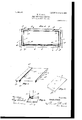
- Figure 1 is mainly a view in front elevation, the doors at the upper left-hand corner being shown as broken out for the purpose of displaying generally the interior arrangement of the shelving and vertical partitions.
- Fig. 2 is a vertical elevation of one end of the cabinet.
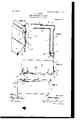
- Fig. 3 is a vertical sectional view on the planer 00, Fig. 1.
- Fig. 4 is a horizontal sectional view on the plane y y, Fig. 1.
- Fig. 5 is a detail in perspective, illustrating a fraction of a shelf.
- Fig. 6 is a detail in perspective, showing in fractional view the front end of one of the vertical partitions.
- FIG. 7 is a horizontal sectional view illustrating, on a larger scale, the method of forming, joining, and bracing the walls at one end of the cabinet.
- Fig. 8 is a perspective view illustrating how the partition engages the upper side of a shelf.
- Fig. 9 is a similar view showing how the partition engages a shelf at its under side.
- Fig. 10 is a perspective showing in detail the construction at an outer corner of the cabinet. 1 1 is a detail showing how the walls are joined 7 to the base.
- 1 designates the end pieces of the outer wall.
- the end pieces are bent to form portions 1 of the back and portions 1 and 1 to form the vertical corners at the front.
- the portion'l forms the front and bolted, if desired, to the vertical edges of the portion 1" of the end piece.
- the end portions 3 and back 3 of the inner wall are shown to be made in one piece, which is formed and set with respect to the outer wall so as to form an air-space all around the back and ends of the cabinet.
- I To connect the inner edges of the portion 1 with the outer edge of the portion 3, I employ a strip bent to form a groove 4, open at its inner edge, a groove 43, open at its outer .edge, and a flat portion 4', standing at right angles to the groove 4 to constitute a brace.
- the outer edge of the end wall 3 fits in the groove 4, while the inner edge of the portion 1 fits in the groove 4 and the bracing portion 4 extends to the inner side of the outer end wall 1.
- edges of the wall 3, portion 1, and the grooved portion of the connectingstrip are bolted or secured together in any suitable manner, as seen at 4
- the inner end walls 3 are horizontally corrugated or grooved, as seen at 3*, to receive and help sustain the ends of the shelves, and the outer walls forming the groove 4 are notched, as seen at 4 to permit the insertion of the edges of the shelves into the grooves 3
- the corners made in the outer wall forming the groove 4* to provide the notches 4 are bent inward against the faces of the groove 3*, as seen at 4".
- a suitable base 5 preferably of heavy sheet metal, stamped, pressed, or bent into proper form and preferably formed with a suitable shoulder for the reception of the outer walls around its outer edge, as indicated at 5*, Fig. 11.
- the lower edge of the outer wall can be bolted, riveted, or otherwise secured in the shoulder 5 and the inner wall can be provided with suitable tongues 53", through which and the upper Wall of the base suitable bolts, rivets, or other fastening devices can be passed.
- shelf 6 designates the shelves. These shelves are made of a single oblong piece of sheet metal bent by suitably doubling the metal twice upon itself along its front edge to form a bead 6 the portions of which project in opposite directions from said edge. This bead prevents sagging of the shelf at the edge, and both its edges are provided with small notches 6, into which the edges of the front portion of the partition are inserted and held.
- the shelf I bend out two ridges or corrugations 6 one projecting from the upper side of the shelf and the other projecting from the-under side thereof. In these ridges are made notches 6, into which the edges of the rear portion of the partition project.
- the extreme rear edge of the shelf is bent to form a bead 6, having an inclined shoulder which when the partition is shoved back into place rests in a groove or corrugation in the inner back wall, said groove corresponding to and forming a continuation of the grooves 3 in the inner end wall.
- the ribs or ridges 6 and the bent shoulder or bead 6 brace the rear portion of the shelf against sagging, and, furthermore, the fact that the bead 6 rests in the groove in the inner back wall also cooperates in effecting this result.
- the shelf can be made of thin sheet metal and still be capable of sustaining great weight.
- 7 designates the partition. This also is of a single thickness of thin sheet metal of substantially rectangular form.
- the doors can be provided with a combination-lock and suitable bolts, operated by a suitable handle somewhat like those parts on an ordinary safe.
- the sheet-metal walls of the cabinet and the doors on their interiors are provided with a sheeting of asbestos 10 to protect them against heat.
- the outer walls of the cabinet may be heated to redness without materially aflecting the inner walls.
- FIG 9 designates the top or crown of the cabinet.
- This crown can be constructed and secured to the upper ends of the walls in any appropriate manner. For the sake of economy it can be made of the same form and material as the base.
- the ends and doors can be made as sunken panels, ornamented in any suitable manner. This paneling of the metal will add to the rigidity of the structure and enhance its appearance.
- a fire-resisting cabinet the combination with a base, of end and back walls of sheet metal, said end wall having an inwardly-standing vertical terminal portion 1 and said back wall having an outwardlystanding vertical terminal, a tie-piece for connecting the said terminals of said end and back walls consisting of a doubly and oppositely grooved piece in which said terminals project, and means for securing said piece to said terminals.
- a tie-piece and brace for connecting the vertical terminals of said end and back walls and bracing the same, consisting of strip of metal bent to form a double groove into which the said terminals project and a wing to constitute the brace.
- a shelf consisting of a sheet of metal having its outer edge bent and folded to form a bracing-bead, portions of which extend in opposite directions from said edge and notches in each of the edges of said flange to receive partitions.
- a shelf consisting of a sheet of metal having its outer edge bent and folded at said edge to form a bracing-bead for the shelf and notches in said bead to receive partitions.
- a shelf consisting of a sheet of metal bent along its rear edge to form a ridge and notches in said ridge to receive partitions.
- a shelf consisting of a sheet of metal bent upwardly and downwardly along its rear edge to form ridges at its upper and lower sides, and notches in said ridges to receive partitions.
- a shelf consisting of a sheet of metal bent and folded at its outer edge to form a strengthening-bead, notches in said bead to receive the forward portion of the edge of a partition, and said shelf bent along its rear edge to form a ridge or rib and notches in said last-named rib to receive the rear portion of the edge of a partition.
- a fire-resisting cabinet the combination with a suitable base, of the vertical casing thereof comprising an outer wall of sheet metal made in three pieces, to wit, end portions 1 having back portions 1 integral therewith extending partially across the back, and
Landscapes
- Assembled Shelves (AREA)
Description
No. 809,497. PATENTED JAN. 9, 1906.
' W. V. DICK.
FIRE RESISTING CABINET.
APPLICATION FILED FEB. 7, 1905.
4 SHEETS-SHEET 1.
Mum
Qua M4 0.
No. 809,497. PATENTED JAN. 9, 1906. W. V. DICK.
FIRE RESISTING CABINET.
APPLICATION FILED IEB. 7, 1905.
4 SHEETS-SKEET 3.
Y Z w I attozwwo UNITED STATES WILLIS V. DICK, OF COLUMBUS, O HIO FIRE-RESISTING CABINET.
Specification of Letters Patent.
Patented Jan. 9, 1906.
Application filed February 7, 1905. Serial No. 244,642.
To all whom it may concern:
Be it known that I, WILLIs V. DIoK, a citizen of the United States, residing at Columbus, in the county of Franklin and State of Ohio, have invented certain new and useful Improvements in Fire-Resisting Cabinets; and I do hereby declare the following to be a full, clear, and exact description of the invention, such as will enable others skilled in the art to which it appertains to make and use the same.
The object of this invention is to provide a fire-resisting cabinet, chiefly of sheet metal, which shall be of simple and economical construction and in which papers, documents, and other perishable things may be stored with reasonable assurance against loss or injury by fire and water, especially in incipient conflagrations.
The invention consists in the details of construction hereinafter described and claimed.
In the accompanying drawings, Figure 1 is mainly a view in front elevation, the doors at the upper left-hand corner being shown as broken out for the purpose of displaying generally the interior arrangement of the shelving and vertical partitions. Fig. 2 is a vertical elevation of one end of the cabinet. Fig. 3 is a vertical sectional view on the planer 00, Fig. 1. Fig. 4 is a horizontal sectional view on the plane y y, Fig. 1. Fig. 5 is a detail in perspective, illustrating a fraction of a shelf. Fig. 6 is a detail in perspective, showing in fractional view the front end of one of the vertical partitions. Fig. 7 is a horizontal sectional view illustrating, on a larger scale, the method of forming, joining, and bracing the walls at one end of the cabinet. Fig. 8 is a perspective view illustrating how the partition engages the upper side of a shelf. Fig. 9 is a similar view showing how the partition engages a shelf at its under side. Fig. 10 is a perspective showing in detail the construction at an outer corner of the cabinet. 1 1 is a detail showing how the walls are joined 7 to the base.
In the several views, 1 designates the end pieces of the outer wall. The end pieces are bent to form portions 1 of the back and portions 1 and 1 to form the vertical corners at the front. The portion'l forms the front and bolted, if desired, to the vertical edges of the portion 1" of the end piece.
3 designates the end portions of the inner wall, and 3 the back portion thereof. The end portions 3 and back 3 of the inner wall are shown to be made in one piece, which is formed and set with respect to the outer wall so as to form an air-space all around the back and ends of the cabinet.
To connect the inner edges of the portion 1 with the outer edge of the portion 3, I employ a strip bent to form a groove 4, open at its inner edge, a groove 43, open at its outer .edge, and a flat portion 4', standing at right angles to the groove 4 to constitute a brace. The outer edge of the end wall 3 fits in the groove 4, while the inner edge of the portion 1 fits in the groove 4 and the bracing portion 4 extends to the inner side of the outer end wall 1. The edges of the wall 3, portion 1, and the grooved portion of the connectingstrip are bolted or secured together in any suitable manner, as seen at 4 The inner end walls 3 are horizontally corrugated or grooved, as seen at 3*, to receive and help sustain the ends of the shelves, and the outer walls forming the groove 4 are notched, as seen at 4 to permit the insertion of the edges of the shelves into the grooves 3 The corners made in the outer wall forming the groove 4* to provide the notches 4 are bent inward against the faces of the groove 3*, as seen at 4".
The structure thus far described is set and secured upon a suitable base 5, preferably of heavy sheet metal, stamped, pressed, or bent into proper form and preferably formed with a suitable shoulder for the reception of the outer walls around its outer edge, as indicated at 5*, Fig. 11. The lower edge of the outer wall can be bolted, riveted, or otherwise secured in the shoulder 5 and the inner wall can be provided with suitable tongues 53", through which and the upper Wall of the base suitable bolts, rivets, or other fastening devices can be passed.
6 designates the shelves. These shelves are made of a single oblong piece of sheet metal bent by suitably doubling the metal twice upon itself along its front edge to form a bead 6 the portions of which project in opposite directions from said edge. This bead prevents sagging of the shelf at the edge, and both its edges are provided with small notches 6, into which the edges of the front portion of the partition are inserted and held. Along the rear portion of the shelf I bend out two ridges or corrugations 6 one projecting from the upper side of the shelf and the other projecting from the-under side thereof. In these ridges are made notches 6, into which the edges of the rear portion of the partition project. The extreme rear edge of the shelf is bent to form a bead 6, having an inclined shoulder which when the partition is shoved back into place rests in a groove or corrugation in the inner back wall, said groove corresponding to and forming a continuation of the grooves 3 in the inner end wall. The ribs or ridges 6 and the bent shoulder or bead 6 brace the rear portion of the shelf against sagging, and, furthermore, the fact that the bead 6 rests in the groove in the inner back wall also cooperates in effecting this result. With this construction of shelf it will be noted that the shelf can be made of thin sheet metal and still be capable of sustaining great weight. 7 designates the partition. This also is of a single thickness of thin sheet metal of substantially rectangular form. As it sustains no weight, it needs no treatment for strengthening it but it is shown to be provided at its front vertical edge with a lip 7, bent to stand at right angles to the plane. of the body of the partition, said lip serving somewhat as a guide for placing the partition and taking the place of an otherwise raw thin edge and enhancing the appearance of the device. The partitionis put into place by setting the lower edge thereof near the lip 7 in a notch 6 and springing the rear end into the notches 6 8 designates doors made up of two thicknesses of sheet metal, so as to be hollow, and therefore light and strong. These doors are provided with lips all around, so as to lap on the front of the cabinet and on each other. The doors can be provided with a combination-lock and suitable bolts, operated by a suitable handle somewhat like those parts on an ordinary safe. The sheet-metal walls of the cabinet and the doors on their interiors are provided with a sheeting of asbestos 10 to protect them against heat. Thus the outer walls of the cabinet may be heated to redness without materially aflecting the inner walls.
9 designates the top or crown of the cabinet. This crown can be constructed and secured to the upper ends of the walls in any appropriate manner. For the sake of economy it can be made of the same form and material as the base.
The ends and doors can be made as sunken panels, ornamented in any suitable manner. This paneling of the metal will add to the rigidity of the structure and enhance its appearance.
I do not confine myself to the exact forms and proportions of the parts shown, because these can be changed without departing from the scope of the invention.
What I claim, and desire to secure by Letters Patent, is
1. In a fire-resisting cabinet, the combination with a base, of end and back walls of sheet metal, said end wall having an inwardly-standing vertical terminal portion 1 and said back wall having an outwardlystanding vertical terminal, a tie-piece for connecting the said terminals of said end and back walls consisting of a doubly and oppositely grooved piece in which said terminals project, and means for securing said piece to said terminals.
2. In a fire-resisting cabinet, the combination with a base, of end and back walls of sheet metal, a tie-piece and brace for connecting the vertical terminals of said end and back walls and bracing the same, consisting of strip of metal bent to form a double groove into which the said terminals project and a wing to constitute the brace.
3. In a fire-resisting cabinet, the combination with the interior and exterior end walls, said interior end walls being provided with shelf-receiving grooves, of a doubly-grooved strip for connecting the vertical terminals of said walls, said strip being notched to permit the insertion of the shelves into said grooves.
4. In a cabinet, a shelf consisting of a sheet of metal having its outer edge bent and folded to form a bracing-bead, portions of which extend in opposite directions from said edge and notches in each of the edges of said flange to receive partitions.
5. In a cabinet, a shelf consisting of a sheet of metal having its outer edge bent and folded at said edge to form a bracing-bead for the shelf and notches in said bead to receive partitions.
6. In a cabinet, a shelf consisting of a sheet of metal bent along its rear edge to form a ridge and notches in said ridge to receive partitions.
7. In a cabinet, a shelf consisting of a sheet of metal bent upwardly and downwardly along its rear edge to form ridges at its upper and lower sides, and notches in said ridges to receive partitions.
8. In a cabinet, a shelf consisting of a sheet of metal bent and folded at its outer edge to form a strengthening-bead, notches in said bead to receive the forward portion of the edge of a partition, and said shelf bent along its rear edge to form a ridge or rib and notches in said last-named rib to receive the rear portion of the edge of a partition.
9. In a fire-resisting cabinet, the combination with a suitable base, of the vertical casing thereof comprising an outer wall of sheet metal made in three pieces, to wit, end portions 1 having back portions 1 integral therewith extending partially across the back, and
portions 1 integral with the end portions ex- In testimony whereof I aflEiX my signature tending partially across the front and a porin presence of two witnesses.
.tion 2 connecting the edges of the portions 1 at the back, and an inner wall also of sheet WILLIS DICK metal extending parallel to the outer wall Witnesses: and joined thereto at or near the edge of the GEORGE -M. FINCKEL,
. wall l substantially as described. I SAMUEL W. LATHAM.
Priority Applications (1)
| Application Number | Priority Date | Filing Date | Title |
|---|---|---|---|
| US24464205A US809497A (en) | 1905-02-07 | 1905-02-07 | Fire-resisting cabinet. |
Applications Claiming Priority (1)
| Application Number | Priority Date | Filing Date | Title |
|---|---|---|---|
| US24464205A US809497A (en) | 1905-02-07 | 1905-02-07 | Fire-resisting cabinet. |
Publications (1)
| Publication Number | Publication Date |
|---|---|
| US809497A true US809497A (en) | 1906-01-09 |
Family
ID=2877978
Family Applications (1)
| Application Number | Title | Priority Date | Filing Date |
|---|---|---|---|
| US24464205A Expired - Lifetime US809497A (en) | 1905-02-07 | 1905-02-07 | Fire-resisting cabinet. |
Country Status (1)
| Country | Link |
|---|---|
| US (1) | US809497A (en) |
Cited By (7)
| Publication number | Priority date | Publication date | Assignee | Title |
|---|---|---|---|---|
| US2769679A (en) * | 1951-10-19 | 1956-11-06 | Joseph H Wiseman | File cabinets |
| US2808307A (en) * | 1953-08-20 | 1957-10-01 | Diebold Inc | Insulated filing cabinet construction |
| US3371627A (en) * | 1966-08-26 | 1968-03-05 | Mosler Safe Co | Modular interior storage safe |
| USD314464S (en) | 1988-02-10 | 1991-02-05 | Justice Robert G | Display safe |
| US5435255A (en) * | 1993-05-14 | 1995-07-25 | Diebold, Incorporated | Modular safe deposit box assembly |
| US20050284345A1 (en) * | 2002-10-01 | 2005-12-29 | Nixdorf International Gmbh | Safe with separately accessible inner areas |
| US7452039B1 (en) * | 2004-08-10 | 2008-11-18 | Metal Fabricating Corporation | Cabinet shelf with keyed slot |
-
1905
- 1905-02-07 US US24464205A patent/US809497A/en not_active Expired - Lifetime
Cited By (8)
| Publication number | Priority date | Publication date | Assignee | Title |
|---|---|---|---|---|
| US2769679A (en) * | 1951-10-19 | 1956-11-06 | Joseph H Wiseman | File cabinets |
| US2808307A (en) * | 1953-08-20 | 1957-10-01 | Diebold Inc | Insulated filing cabinet construction |
| US3371627A (en) * | 1966-08-26 | 1968-03-05 | Mosler Safe Co | Modular interior storage safe |
| USD314464S (en) | 1988-02-10 | 1991-02-05 | Justice Robert G | Display safe |
| US5435255A (en) * | 1993-05-14 | 1995-07-25 | Diebold, Incorporated | Modular safe deposit box assembly |
| DE4415914C2 (en) * | 1993-05-14 | 2003-10-30 | Diebold Inc Canton | Safe structure |
| US20050284345A1 (en) * | 2002-10-01 | 2005-12-29 | Nixdorf International Gmbh | Safe with separately accessible inner areas |
| US7452039B1 (en) * | 2004-08-10 | 2008-11-18 | Metal Fabricating Corporation | Cabinet shelf with keyed slot |
Similar Documents
| Publication | Publication Date | Title |
|---|---|---|
| US2696419A (en) | Frame and panel type storage furniture | |
| US3252614A (en) | Stackable pan | |
| US2520506A (en) | Sectional wall cabinet | |
| US809497A (en) | Fire-resisting cabinet. | |
| US3182809A (en) | Locker caddy | |
| US1222451A (en) | Furniture-drawer. | |
| US1450180A (en) | Cabinet construction | |
| US3472571A (en) | Cabinet formed of grooved and folded laminated panels | |
| US1806610A (en) | Furniture | |
| US1920855A (en) | Sliding door cabinet | |
| US419920A (en) | Sectional kitchen-safe | |
| US570391A (en) | Fireproof door | |
| US1259210A (en) | Expanded-metal frame. | |
| US3294276A (en) | Structural members and cabinets utilizing such members | |
| US1178611A (en) | Base-section for metallic furniture. | |
| US436668A (en) | Portable storm-house | |
| US1962826A (en) | Partition panel joint | |
| US751435A (en) | Metallic furniture | |
| US1828642A (en) | Screen | |
| US1802600A (en) | Panel for doors and the like | |
| US2153204A (en) | Ironclad door | |
| US657661A (en) | Storage or show case. | |
| US997567A (en) | Metal furniture. | |
| US3230025A (en) | Cabinet | |
| US1030279A (en) | Knockdown extensible cabinet or shelving. |