US809478A - Truck. - Google Patents
Truck. Download PDFInfo
- Publication number
- US809478A US809478A US24524105A US1905245241A US809478A US 809478 A US809478 A US 809478A US 24524105 A US24524105 A US 24524105A US 1905245241 A US1905245241 A US 1905245241A US 809478 A US809478 A US 809478A
- Authority
- US
- United States
- Prior art keywords
- truck
- chute
- frame
- conveyer
- bars
- Prior art date
- Legal status (The legal status is an assumption and is not a legal conclusion. Google has not performed a legal analysis and makes no representation as to the accuracy of the status listed.)
- Expired - Lifetime
Links
Images
Classifications
-
- B—PERFORMING OPERATIONS; TRANSPORTING
- B60—VEHICLES IN GENERAL
- B60P—VEHICLES ADAPTED FOR LOAD TRANSPORTATION OR TO TRANSPORT, TO CARRY, OR TO COMPRISE SPECIAL LOADS OR OBJECTS
- B60P1/00—Vehicles predominantly for transporting loads and modified to facilitate loading, consolidating the load, or unloading
- B60P1/36—Vehicles predominantly for transporting loads and modified to facilitate loading, consolidating the load, or unloading using endless chains or belts thereon
Definitions
- My invention relates to trucks, and has for its principal object the provision of such an apparatus adapted for the transferring and piling up of various objects, and more particularly merchandise in bags-for example, sugar.
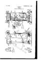
- Figure 1 is a side elevation of one embodiment of my invention, parts being broken away.
- Fig. 2 is an end elevation thereof.
- Fig. 3 is a horizontal section on the line 3 3 of Fig. 1.
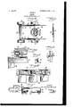
- Fig. 4 is an enlarged sectional detail through a portion of the conveyer and the supporting-frame.
- Fig. 5 is a bottom plan View of a portion of said conveyer.
- Fig. 6 is a vertical sectional detail illustrating the means for fixing the position of the chute.
- Fig. 7 is an enlarged transverse sectional detail on the line 7 7 of Fig. 8, particularly showing the locking device for the conveyer.
- Fig. 8 is an end elevation of said locking device looking from the left in Fig. 7.
- Fig. 9 is a perspective View of a socket for one of the guide-rods, and
- Fig. 10 is a similar View of said guide-rod.
- A designates a frame, which is preferably constructed of angle-iron, and consists of uprights 10, cross-bars 11, and braces 12. At the forward end of the frame, on the lower extremities of the uprights, is supported an axle .13, upon which are journaled wheels 14 14. At the rear of the frame a similar axle 15 carries wheels 15a 15a and may turn about a king-bolt 16, passing through a cross-bar 16 of the frame. Upon this cross-bar and upon the axle are xed the sections 17 and 18 of a fifth-wheel, the latter section being pro- 'vided with internal gear-teeth 19.
- a pinion 20 fixed upon a steering-shaft 21, journaled in brackets 22, projecting rearwardly from the frame.
- This shaft terminates considerably below the upper portion of the frame and is provided with some steering device or handhold, such as a wheel 23, which is situated at such a ⁇ height above the surface over which the truck is passing that it may be conveniently operated by a person pushing the truck before him.
- the supporting-platform of the truck is furnished by a conveyer, which may consist of transverse barsor slats 26, here shown as connected by strips 27 27, which may be of sheet-steel or other flexible material and have recesses 28, in which are journaled rolls 29, which operate over the ways furnished by the flanges 24.
- a shaft 31 is journaled in bearings 32 and has an extended lateral projection 33, which may be swung between adjacent conveyer-bars to lock said conveyer in place or moved outwardly to clear l and allow its movement.
- one end of the shaft has lixed upon it a handle 34, which coacts with a spring retaining-sector 35, having two recesses 36 and 37.
- a chute 39 Pivoted upon the forward uprights by means of brackets 38, fixed just below the end of the conveyer, is a chute 39, to the lower portion of the opposite sides of which may be hinged curved bars or operating members 40. These bars pass through guide-openings 41 in the uprights, and each has a pivoted end seotion 42, which when the chute is in its vertical position, as is illustrated in full lines in Fig. 1 of the drawings, will hang in comparatively close proximity to the rear uprights and be out of the way, but when raised furnishes a continuation of the forward section IOO . for a suitable distance.
- each bar In each bar are a plurality of retaining-notches, here shown as two in number, one, 43, being in the forward bar-section and the second, 44, in the rear section. These may be brought into engagement with the edge of the forward guide-openings and retain the chute at different angles, one of which is shown in dotted lines in Fig. l.
- sockets' 45 and 46 are fixed upon the uprights and the curved ends of the flanges 25 at the opposite sides of the truck, and in these are supported rods 47, projecting rearwardly and upwardly
- the rods may be retained in this position by projections 48 thereon, which engage angular locking-recesses 49 in the socket 46.
- the truck Arrived at the point on the pier at which the pile of bags is to be erected the truck is stopped in such position that when the chute is extended at its maximum angle, the notches 44 engaging the forward uprights, the outer extremity of said chute will be directly over the place at which the first bag is to be deposited. Then the conveyer is unlocked by moving the handle 34 into the recess 36 and the bags caused to travel with the conveyer until the one nearer the chute drops upon it and slides to the pier, the descent being rendered so gradual that there is no danger of bursting the bag.
- the bars may then be swung inwardly until the notches 43 coact with the uprights, which positions the chute properly to deliverv the next bag adjacent to that which preceded it,it being unloaded in the same manner by pushing the conveyer forward.
- the truck is then returned to the loadingpoint and the operation repeated', but on its return to the pile it is unnecessary to project the chute, since the presence of the bags already upon the pier furnishes a cushion which obviates the danger of bursting, the travel cf the conveyer causing the bags to fall directly upon those which have preceded them. This continues until the pile reaches the desired height, which is still below the level of the upper run of the conveyer, thus making it needless to at any time lift the bags.
- this truck is not only convenient for use in contracted areas, but also entirely does away with the necessity for lifting the objects transferred and avoids the danger of bursting the containers and spilling the contents.
- a truck comprising a frame having uprights, a platform mounted at the upper extremities thereof, cross-bars connectingthe uprights, pairs of wheels upon which the frame is supported, and a steering-shaft journaled in theY cross-bars and connected with one of the pairs of wheels, said steering-shaft terminating below the platform.
- a truck comprising a wheeled frame having opposite ways and provided with downwardly and inwardly curved end portions.
- a truck comprising a wheeled frame having opposite ways, an endless series of connected bars movable over the ways, and a locking device movable between the bars.
- a truck comprising a wheeled frame, a conveyer mounted upon the frame and furnishing a platform, and a chute pivoted upon the frame below one extremity of the conveyer.
- a truck comprising a wheeled frame having supporting-ways, a iiexible, endless traveling platform having its upper run movable over the ways, and means to lock said flexible platform against movement.
- a truck comprising a wheeled frame having elevated supporting-ways, a flexible, endless traveling platform having its upper run movable over the ways, a chute having its upper end pivotally connected to the frame at a point below the discharge portion of the traveling platform, and means to adjust the chute and support it in adjusted position.
- a truck comprising a wheeled frame having elevated supporting-ways, a iexible, endless traveling platform having its upper run movable over the ways, a chute having its upper end pivotally connected to the frame at a point below the discharge portion of the traveling platform, and means to adjust the chute and support and lock it in adjusted position.
- a truck comprising a wheeled frame, an elevated platform mounted thereon, a chute pivoted upon the frame, and an operating member including two sections, one of which is connected with the chute and the other piv- IOO IIO
- a truck comprising a Wheeled frame having guide-openings in its front and rear sides, an elevated platform supported on said frame, a chute having itsupper end pivoted to one side of the frame under the discharge portion of the platform, and curved operatingbars pivotally connected together and pivotally connected to the chute, said operatingbars extending through the guide-openings in the frame and having stop devices to coact With the sides of said openings to lock said bars and hence said chute in adjusted position.
Landscapes
- Engineering & Computer Science (AREA)
- Transportation (AREA)
- Mechanical Engineering (AREA)
- Chutes (AREA)
Description
10.809,478. PATBNTBD JAN. 9, 1906.
P. TWOMBY. TRUCK.
APPLICATION FILED FEB. 11. 1906.
2 SHEETg-SHBET 1.
UNITED sTATEs PATENT oEEioE.
No. soa/178.
Specification of Letters Patent.
Patented Jan. 9, 1906.
Application iled February 1l, 1905. Serial No. 245,241.
To a/ZZ whom t may concern:
Be it known that l, PATRICK TWOMEY, a citizen of the United States, and a resident of the city of New York, borough ofthe Bronx, in the county and State of New York, have invented a new and Improved Truck, of which the following is a full, clear, and exact description. v
My invention relates to trucks, and has for its principal object the provision of such an apparatus adapted for the transferring and piling up of various objects, and more particularly merchandise in bags-for example, sugar.
It consists in the various features and combinations hereinafter described and more particularly claimed.'
Reference is to be had to the accompanying drawings, forming a part of this specification, in which similar characters of reference indicate corresponding yparts in all the views.
Figure 1 is a side elevation of one embodiment of my invention, parts being broken away. Fig. 2 is an end elevation thereof. Fig. 3 is a horizontal section on the line 3 3 of Fig. 1. Fig. 4 is an enlarged sectional detail through a portion of the conveyer and the supporting-frame. Fig. 5 is a bottom plan View of a portion of said conveyer. Fig. 6 is a vertical sectional detail illustrating the means for fixing the position of the chute. Fig. 7 is an enlarged transverse sectional detail on the line 7 7 of Fig. 8, particularly showing the locking device for the conveyer. Fig. 8 is an end elevation of said locking device looking from the left in Fig. 7. Fig. 9 is a perspective View of a socket for one of the guide-rods, and Fig. 10 is a similar View of said guide-rod.
A designates a frame, which is preferably constructed of angle-iron, and consists of uprights 10, cross-bars 11, and braces 12. At the forward end of the frame, on the lower extremities of the uprights, is supported an axle .13, upon which are journaled wheels 14 14. At the rear of the frame a similar axle 15 carries wheels 15a 15a and may turn about a king-bolt 16, passing through a cross-bar 16 of the frame. Upon this cross-bar and upon the axle are xed the sections 17 and 18 of a fifth-wheel, the latter section being pro- 'vided with internal gear-teeth 19. With these teeth meshes a pinion 20, fixed upon a steering-shaft 21, journaled in brackets 22, projecting rearwardly from the frame. This shaft terminates considerably below the upper portion of the frame and is provided with some steering device or handhold, such as a wheel 23, which is situated at such a` height above the surface over which the truck is passing that it may be conveniently operated by a person pushing the truck before him.
At the Lipper ends of the' uprights, which are so elevated as to be somewhat above the level of the top of the pile of objects which it is desired to form, are supported longitudinally-extending angle-irons having horizontal ianges 24, furnishing ways, and outer vertical ianges 25. The supporting-platform of the truck is furnished by a conveyer, which may consist of transverse barsor slats 26, here shown as connected by strips 27 27, which may be of sheet-steel or other flexible material and have recesses 28, in which are journaled rolls 29, which operate over the ways furnished by the flanges 24. Lateral movement-of the conveyer is prevented by the contact of the ends of the bars with the flanges 25, while the opposite extremities of these supporting angle-irons are bent downwardly and inwardly at 30 to guide the con veyer upon an easy curvature. Upon the ways, preferably just above the steering-wheel, a shaft 31 is journaled in bearings 32 and has an extended lateral projection 33, which may be swung between adjacent conveyer-bars to lock said conveyer in place or moved outwardly to clear l and allow its movement. To retain the locking projection in the desired position, one end of the shaft has lixed upon it a handle 34, which coacts with a spring retaining-sector 35, having two recesses 36 and 37. When the handle lies within the former, the locking projection is out of the path of the conveyerbars; but when it rests in the recess 37 the projection is between two of the bars and the conveyer is temporarily fixed in position.
Pivoted upon the forward uprights by means of brackets 38, fixed just below the end of the conveyer, is a chute 39, to the lower portion of the opposite sides of which may be hinged curved bars or operating members 40. These bars pass through guide-openings 41 in the uprights, and each has a pivoted end seotion 42, which when the chute is in its vertical position, as is illustrated in full lines in Fig. 1 of the drawings, will hang in comparatively close proximity to the rear uprights and be out of the way, but when raised furnishes a continuation of the forward section IOO . for a suitable distance.
of the bar. In each bar are a plurality of retaining-notches, here shown as two in number, one, 43, being in the forward bar-section and the second, 44, in the rear section. These may be brought into engagement with the edge of the forward guide-openings and retain the chute at different angles, one of which is shown in dotted lines in Fig. l.
To guard the rear of the platform or conveyer, so that the objects carried thereon may not become displaced and fall upon the user, and to support a fall and tackle, sockets' 45 and 46 are fixed upon the uprights and the curved ends of the flanges 25 at the opposite sides of the truck, and in these are supported rods 47, projecting rearwardly and upwardly The rods may be retained in this position by projections 48 thereon, which engage angular locking-recesses 49 in the socket 46. When the truck is to be loaded, the projections 'may be withdrawn from the recesses and the rods slipped through the sockets until said projections contact with the sockets 45, this bringing the outer ends of the rods within the outer surface of the conveyer, so that they will not interfere with the operation.
Considering the use of my improved truck for handling bags of sugar, it is placed in proximity to the vessel from which the bags are to be removed and these are loaded upon it by the usual tackle which is employed in removing the cargo from the hold. In the form illustrated the platform is adapted for supporting two of the bags, this giving a weight which one man can readily move. The truck having been thus loaded and the conveyer fixed in place, the handle of the locking device being in the recess 37, said truck is pushed before the user, who directs it by turning the 'steering-wheel. 'Ihe chute and chute-bar end sections are at this time lowered, and the entire absence of projecting elements renders the truck readily moved through comparatively narrow spaces. Arrived at the point on the pier at which the pile of bags is to be erected the truck is stopped in such position that when the chute is extended at its maximum angle, the notches 44 engaging the forward uprights, the outer extremity of said chute will be directly over the place at which the first bag is to be deposited. Then the conveyer is unlocked by moving the handle 34 into the recess 36 and the bags caused to travel with the conveyer until the one nearer the chute drops upon it and slides to the pier, the descent being rendered so gradual that there is no danger of bursting the bag. After moving the truck the bars may then be swung inwardly until the notches 43 coact with the uprights, which positions the chute properly to deliverv the next bag adjacent to that which preceded it,it being unloaded in the same manner by pushing the conveyer forward. The truck is then returned to the loadingpoint and the operation repeated', but on its return to the pile it is unnecessary to project the chute, since the presence of the bags already upon the pier furnishes a cushion which obviates the danger of bursting, the travel cf the conveyer causing the bags to fall directly upon those which have preceded them. This continues until the pile reaches the desired height, which is still below the level of the upper run of the conveyer, thus making it needless to at any time lift the bags.
It will be seen from the above description that this truck is not only convenient for use in contracted areas, but also entirely does away with the necessity for lifting the objects transferred and avoids the danger of bursting the containers and spilling the contents.
Having thus described my invention, I claim as new and desire to secure by Letters Patent- 1. A truck comprising a frame having uprights, a platform mounted at the upper extremities thereof, cross-bars connectingthe uprights, pairs of wheels upon which the frame is supported, and a steering-shaft journaled in theY cross-bars and connected with one of the pairs of wheels, said steering-shaft terminating below the platform.
2. A truck comprising a wheeled frame having opposite ways and provided with downwardly and inwardly curved end portions.
3. A truck comprising a wheeled frame having opposite ways, an endless series of connected bars movable over the ways, and a locking device movable between the bars.
4. A truck comprising a wheeled frame, a conveyer mounted upon the frame and furnishing a platform, and a chute pivoted upon the frame below one extremity of the conveyer.
5. A truck comprising a wheeled frame having supporting-ways, a iiexible, endless traveling platform having its upper run movable over the ways, and means to lock said flexible platform against movement.
6. A truck comprising a wheeled frame having elevated supporting-ways, a flexible, endless traveling platform having its upper run movable over the ways, a chute having its upper end pivotally connected to the frame at a point below the discharge portion of the traveling platform, and means to adjust the chute and support it in adjusted position.
' 7. A truck comprisinga wheeled frame having elevated supporting-ways, a iexible, endless traveling platform having its upper run movable over the ways, a chute having its upper end pivotally connected to the frame at a point below the discharge portion of the traveling platform, and means to adjust the chute and support and lock it in adjusted position.
8. A truck comprisinga wheeled frame, an elevated platform mounted thereon, a chute pivoted upon the frame, and an operating member including two sections, one of which is connected with the chute and the other piv- IOO IIO
ISO
Ulv
` stops to coact With said guides to look the bars to the frame and secure the chute in adjusted position.
lO. A truck comprising a Wheeled frame having guide-openings in its front and rear sides, an elevated platform supported on said frame, a chute having itsupper end pivoted to one side of the frame under the discharge portion of the platform, and curved operatingbars pivotally connected together and pivotally connected to the chute, said operatingbars extending through the guide-openings in the frame and having stop devices to coact With the sides of said openings to lock said bars and hence said chute in adjusted position.
In testimony whereof I have signed my name to this specification in the presence of two subscribing Witnesses.
PATRICK TWoMEY.
Witnesses:`
JN0. M. RITTER, SYLvANUs H. COBB.
Priority Applications (1)
| Application Number | Priority Date | Filing Date | Title |
|---|---|---|---|
| US24524105A US809478A (en) | 1905-02-11 | 1905-02-11 | Truck. |
Applications Claiming Priority (1)
| Application Number | Priority Date | Filing Date | Title |
|---|---|---|---|
| US24524105A US809478A (en) | 1905-02-11 | 1905-02-11 | Truck. |
Publications (1)
| Publication Number | Publication Date |
|---|---|
| US809478A true US809478A (en) | 1906-01-09 |
Family
ID=2877959
Family Applications (1)
| Application Number | Title | Priority Date | Filing Date |
|---|---|---|---|
| US24524105A Expired - Lifetime US809478A (en) | 1905-02-11 | 1905-02-11 | Truck. |
Country Status (1)
| Country | Link |
|---|---|
| US (1) | US809478A (en) |
-
1905
- 1905-02-11 US US24524105A patent/US809478A/en not_active Expired - Lifetime
Similar Documents
| Publication | Publication Date | Title |
|---|---|---|
| US493542A (en) | Display-shelf and carpet-elevator | |
| US1142088A (en) | Load-supporting rack. | |
| US809478A (en) | Truck. | |
| US607329A (en) | The morris petebs co | |
| US1095077A (en) | Elevating apparatus. | |
| GB2273691A (en) | A movable, load-supporting apparatus | |
| US345467A (en) | Barrel-truck | |
| US466899A (en) | Truck | |
| DK178115B1 (en) | Sack Truck | |
| ES2709384T3 (en) | Lifting device for shopping carts | |
| US1424819A (en) | Basket truck | |
| WO2001002281A1 (en) | Load handling apparatus | |
| US507008A (en) | Stacker | |
| US369984A (en) | Wool-packing frame | |
| US312763A (en) | Invalid-supporter | |
| US965493A (en) | Truck. | |
| US214233A (en) | Improvement in elevators | |
| US312016A (en) | Combined truck and bag-holder | |
| US2278946A (en) | Article elevating machine | |
| US1530564A (en) | Portable conveyer | |
| US1236648A (en) | Portable elevator. | |
| US813448A (en) | Loading apparatus. | |
| US350001A (en) | Hand-truck | |
| BE1027461B1 (en) | Device for loading goods into and taking out goods from a rack of a warehouse or the like | |
| US598119A (en) | Loading or unloading machine |