US809474A - Water-gage mechanism. - Google Patents
Water-gage mechanism. Download PDFInfo
- Publication number
- US809474A US809474A US24831405A US1905248314A US809474A US 809474 A US809474 A US 809474A US 24831405 A US24831405 A US 24831405A US 1905248314 A US1905248314 A US 1905248314A US 809474 A US809474 A US 809474A
- Authority
- US
- United States
- Prior art keywords
- carrier
- tap
- occluder
- attachment
- extremity
- Prior art date
- Legal status (The legal status is an assumption and is not a legal conclusion. Google has not performed a legal analysis and makes no representation as to the accuracy of the status listed.)
- Expired - Lifetime
Links
- 210000003414 extremity Anatomy 0.000 description 18
- 238000012856 packing Methods 0.000 description 10
- 230000015556 catabolic process Effects 0.000 description 1
- 238000010276 construction Methods 0.000 description 1
- 230000001276 controlling effect Effects 0.000 description 1
- 230000000694 effects Effects 0.000 description 1
- 238000004519 manufacturing process Methods 0.000 description 1
- 239000000463 material Substances 0.000 description 1
- 230000001105 regulatory effect Effects 0.000 description 1
- 238000006467 substitution reaction Methods 0.000 description 1
- 210000001364 upper extremity Anatomy 0.000 description 1
- XLYOFNOQVPJJNP-UHFFFAOYSA-N water Substances O XLYOFNOQVPJJNP-UHFFFAOYSA-N 0.000 description 1
Images
Classifications
-
- F—MECHANICAL ENGINEERING; LIGHTING; HEATING; WEAPONS; BLASTING
- F16—ENGINEERING ELEMENTS AND UNITS; GENERAL MEASURES FOR PRODUCING AND MAINTAINING EFFECTIVE FUNCTIONING OF MACHINES OR INSTALLATIONS; THERMAL INSULATION IN GENERAL
- F16K—VALVES; TAPS; COCKS; ACTUATING-FLOATS; DEVICES FOR VENTING OR AERATING
- F16K1/00—Lift valves or globe valves, i.e. cut-off apparatus with closure members having at least a component of their opening and closing motion perpendicular to the closing faces
Definitions
- This invention relates to a water-gage mechanism for use on steam-boilers, and the most essential feature or advantage in the present mechanism is that the use of the usual valves is entirely dispensed with and all the parts are readily accessible for repair or substitution and easily controllable from either one of two elements of the mechanism.
- watergages or gage mechanism of this class as heretofore constructed valves have been employed which at intervals required grinding and are so inclosed that a disorganization of the several devices cooperating therewith is necessary in order to effect a practical repair and also requiring the re to be pulled to permit handling of the several parts.
- a further advantage resulting from the non-use of valves is that there are no parts to corrode or scale, and the operation in the present instance, so far as the contributing elements are concerned, is positive and reliable at all times.
- the present attachment also has two points of operation to allow a fireman or engineer to manipulate the same as desired at either one of the two points in the event thatl one of the operating means becomes disarranged or inoperative.
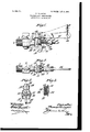
- Figure 1 is a side elevation of a steam-boiler, pipe-gage, or gage attachment embodying the features of the invention and shown open in dotted-line position.
- Fig. 2 is a top plan view of the same.
- Fig. ⁇ 3 is a front end elevation.
- Fig. 4 is a transverse vertical section on the line 4 4,
- the numeral 1 designates a tap or nozzleplug with a screw-threaded extremity 2 for attachment to a boiler-top or other surface, an intermediate plug-valve 3 controlling a bore 4, extending longitudinally through the tap or plug.
- the outer extremity 5 of the ⁇ tap or plug is reduced and terminates in a guard-flange 6 for application thereto of an occluding or closing means, which will be presently set forth.
- Extending upwardly and outwardly from the reduced extremity 5 is a supporting neck or bracket 7, terminating at its free end in longitudinal alinemcnt with the center of the said extremity 5 in a bearing 8, which is provided with a lower stop projection 9, having an angular end 10.
- the neck or bracket 7 is formed with an intermediate slotted enlargement 11, which receives the upper end of a depending arm 12 and is held in applied position by a cross-pin 13, on which the said arm has pivotal movement.
- the arm 12 is held in normal vertical position by a spring 14, having its rear end seated centrally ⁇ in the said arm and its outer end secured to the inner terminal or head -15 of an adjusting-screw 16, disposed inthe bearing 8 and having an outer adjusting-head 17 and a set-nut or analogous device 18, which is adapted to abut against the outer terminal of the bearing.
- the arm 12 has a lower terminal eye 19, to which an operating-cord or other device is adapted to be attached, and above the eye is a forwardly-extending stop projection20, with an inclined end 21 to contact with the end 10 of the projection 9, and thereby limit the outward movement of the arm.
- the opposite sides of the arm 12 at an intermediate point have outstanding lugs or analogous devices 22, and the rear or inner edge of said arm is provided with a boss 23, having-a slot 24 therein.
- an occluder or packing attachment 25 preferably formed of rubber and having a recess 26 in its inner IIO face to receive the guard- ⁇ iange 6 of the reduced extremity 5 of the tap or plug 1.
- the occluder or packing 25 is removably held on the boss 23 by a lockingkey 27, passing through the said occluder or packing and the boss and adapting the occluder or packing to be readily removed and replaced when found necessary.
- the main operating means for the attachment consists of a handle-bar or lever 28, having an outer apertured extremity 29 and an inner bifurcated extremity 30, which straddles or embraces the intermediate enlargement 11 of the neck or bracket 7.
- the inner bifurcated extremity 30 of the handle-bar or lever 28 is held in applied position also by the pin 13, which passes therethrough, andl depending from and simultaneously operating with the inner ends of the bifurcation is a fork consisting of opposite arms 31, having their lower free ends interposed between the lugs 22 and the rear portion of the arm 12 or packing 25.
- the arms 31 are long enough to always remain in operative engagement behind the lugs 22 irrespective of the maximum movement of the arm 12, and to actuatc the handle-bar or main operating-lever 28, especially where the attachment is at considerable elevation above the base-rest or the furnace and boiler, a cord, chain, or other analogous device 32 is attached to the outer end of said bar or lever and arranged in such manner that a downward pull thereon will elevate the bar or lever and throw the arm 12 outwardly through the operation of the fork comprising the arms 31.
- the lower eye extremity of the arm 12 will have a pulling device secured thereto, and by this means the attachment may be operated from either one of two points.
- the precise mode of operating the arm 12 and the handle or lever 28 is not essential and will depend altogether on the height or elevation of the same with respect to the boiler, withwhich the attachment is applied. for cooperation.
- the occluder or packing 25 may be released or thrown outwardly away from the guard-flange 6 at the outer end of the reduced extremity 5 of the tap or plug 1, such outward movement being against the restriction of the spring 14, and when the parts are released the said spring will cause them to return to normal position.
- the occluder or packing 25 may be released or thrown outwardly away from the guard-flange 6 at the outer end of the reduced extremity 5 of the tap or plug 1, such outward movement being against the restriction of the spring 14, and when the parts are released the said spring will cause them to return to normal position.
- the occluder or packing 25 may be released or thrown outwardly away from the guard-flange 6 at the outer end of the reduced extremity 5 of the tap or plug 1, such outward movement being against the restriction of the spring 14, and when the parts are released the said spring will cause them to return to normal position.
- all the parts are exposed and may be replaced by other like parts or irregularities therein corrected without disconnecting the attachment from the boiler or requiring any change in the condition
- a device of the class set forth the combination with a tap having an open end, of a carrier pivotally supported adjacent to the open end of the tap and located exteriorly of the latter, the said carrier being transversely disposed with respect to the tap, a flexible occluder removably held on a portion of the carrier to engage the open end of the tap, exteriorly-located resilient means for automatically closing the carrier and occluder and exerting a pressure force on the said carrier in longitudinal alinement with the tap, and devices for releasing the occluder and simultaneously moving the carrier, said devices providing two independent points for opening the occluder and moving the carrier therewith.
- a device of the class set forth the combination with a tap having an open end surrounded by a flange. of a depending carrier pivotally supported at its upper extremity by and located wholly exteriorly of the tap and provided with a flexible occluder cooperating directly with the open end of the tap, the occluder having a recess to inclose the flanged open end of the tap, and adjustable resilient means for automatically closing the carrier and occluder carried by the latter and exerting a longitudinal pressure on the carrier, and a pivoted lever device having depending members embracing and loosely engaging opposite portions of the carrier to open the latter against the resistance of the resilient means.
- the combination with a tap, of adepending pivotally-mounted carrier having an occluder to cooperate with a part of the tap and also provided with a lower terminal operating means, an adjustable device for automatically closing the carrier and occluder, and an operating-leverhavingdependingmembersbearingagainst opposite portions of the carrier.
- a tap having a bracket projecting outwardly therefrom and terminating at its free end in a stop projection
- a carrier movably depending from the bracket and having an occluder thereon to engagea portion of the tap
- the carrier also having a stop projection to engage that on the bracket
- a spring interposed between the outer end of the bracket and carrier for automatically closing the carrier, and means for opening the carrier against the resistance of the spring.
- a tap having a bracket projecting outwardly therefrom, a carrier movably depending from the bracket, an occluder removably held on a part of the carrier to engage the tap, a key extending through the occluder and part of the carrier with which it engages, ⁇ and devices for opening and closing the carrier and occluder.
- a tap having supporting means projectingoutwardly therefrom, acarrier movably depending from the supporting means and having an occluder to engage a part of the tap the outer terminal of the supporting means projecting beyond the carrier, an adjustingscrew mounted in the outer terminal of the supporting means, a spring connected at opposite extremities to the carrier and screw, the spring exerting a direct longitudinal pressure against the carrier and occluder, and means for opening the carrier against the resistance of the spring.
- a tap having supporting means projecting outwardly therefrom and terminating in aseat and a stop device
- a carrier movably depending from the supporting means and having an occluder to engage one terminal of the tap and also provided with a stop projection to contact with the stop device of the supporting means
- an adjusting-screw mounted in the seat of the supporting means
- aspring connected at opposite extremities to the carrier and screw, and means for opening the carrier against the resistance of the spring.
Landscapes
- Engineering & Computer Science (AREA)
- General Engineering & Computer Science (AREA)
- Mechanical Engineering (AREA)
- Mechanically-Actuated Valves (AREA)
Description
PATENTED JAN. 9, 1906.
T. STRINGER. WATER GAGE MEGHANISM.
APPLICATION FILED MAR.3,1905.
LL/y g m..
UNITED STATES PATENT oEEIcE.
Specification of Letters Patent.
Patented Jan. 9, 1906. A
Application filed March 3, 1905. Serial No. 248.314.
To all whom t may concern:
Be it known that I, THOMAS STRINGER, a citizen of the United States, residing at Girard, in the county of Trumbull and State of Ohio, have invented new and usefulImprovements in Water-Gage Mechanism, of which the following is a specification.
This invention relates to a water-gage mechanism for use on steam-boilers, and the most essential feature or advantage in the present mechanism is that the use of the usual valves is entirely dispensed with and all the parts are readily accessible for repair or substitution and easily controllable from either one of two elements of the mechanism. In watergages or gage mechanism of this class as heretofore constructed valves have been employed which at intervals required grinding and are so inclosed that a disorganization of the several devices cooperating therewith is necessary in order to effect a practical repair and also requiring the re to be pulled to permit handling of the several parts. A further advantage resulting from the non-use of valves is that there are no parts to corrode or scale, and the operation in the present instance, so far as the contributing elements are concerned, is positive and reliable at all times.
All the parts of the present attachment are visible and readily accessible, and should a breakdown ensue the mechanism may be cut 0E from the boiler by a stop-cock or analogous device forminga part of the attachment and permitting repair to be performed without in the least detracting from the condition of the boiler or the furnace.
In the present im proved attachment the construction is comparatively simple and also strong and durable, and though a packing is used as an occluding means it is readily replaceable in view of the fact that the securing means therefor can be quickly reached and removed or reapplied.
The present attachment also has two points of operation to allow a fireman or engineer to manipulate the same as desired at either one of the two points in the event thatl one of the operating means becomes disarranged or inoperative.
In the drawings, Figure 1 is a side elevation of a steam-boiler, pipe-gage, or gage attachment embodying the features of the invention and shown open in dotted-line position. Fig. 2 is a top plan view of the same. Fig.`3 is a front end elevation. Fig. 4 is a transverse vertical section on the line 4 4,
Fig. 2, through the closing-gasket or packing device.
Similar numerals of reference are employed to indicate corresponding parts in the several views.
The numeral 1 designates a tap or nozzleplug with a screw-threaded extremity 2 for attachment to a boiler-top or other surface, an intermediate plug-valve 3 controlling a bore 4, extending longitudinally through the tap or plug., The outer extremity 5 of the` tap or plug is reduced and terminates in a guard-flange 6 for application thereto of an occluding or closing means, which will be presently set forth. Extending upwardly and outwardly from the reduced extremity 5 is a supporting neck or bracket 7, terminating at its free end in longitudinal alinemcnt with the center of the said extremity 5 in a bearing 8, which is provided with a lower stop projection 9, having an angular end 10. As Shown by Fig. 2, the neck or bracket 7 is formed with an intermediate slotted enlargement 11, which receives the upper end of a depending arm 12 and is held in applied position by a cross-pin 13, on which the said arm has pivotal movement. The arm 12 is held in normal vertical position by a spring 14, having its rear end seated centrally` in the said arm and its outer end secured to the inner terminal or head -15 of an adjusting-screw 16, disposed inthe bearing 8 and having an outer adjusting-head 17 and a set-nut or analogous device 18, which is adapted to abut against the outer terminal of the bearing. Through the medium ofthe screw 16 the tension of the spring 14 may be adjusted at will, as found necessary or required, and in outwardly moving the arm through means which will be presently set forth such operation ensues against the resistance of the spring, as will be readily understood. The arm 12 has a lower terminal eye 19, to which an operating-cord or other device is adapted to be attached, and above the eye is a forwardly-extending stop projection20, with an inclined end 21 to contact with the end 10 of the projection 9, and thereby limit the outward movement of the arm. The opposite sides of the arm 12 at an intermediate point have outstanding lugs or analogous devices 22, and the rear or inner edge of said arm is provided with a boss 23, having-a slot 24 therein. Over the boss is fitted the recessed outer side of an occluder or packing attachment 25, preferably formed of rubber and having a recess 26 in its inner IIO face to receive the guard-{iange 6 of the reduced extremity 5 of the tap or plug 1. The occluder or packing 25 is removably held on the boss 23 by a lockingkey 27, passing through the said occluder or packing and the boss and adapting the occluder or packing to be readily removed and replaced when found necessary.
The main operating means for the attachment consists of a handle-bar or lever 28, having an outer apertured extremity 29 and an inner bifurcated extremity 30, which straddles or embraces the intermediate enlargement 11 of the neck or bracket 7. The inner bifurcated extremity 30 of the handle-bar or lever 28 is held in applied position also by the pin 13, which passes therethrough, andl depending from and simultaneously operating with the inner ends of the bifurcation is a fork consisting of opposite arms 31, having their lower free ends interposed between the lugs 22 and the rear portion of the arm 12 or packing 25. The arms 31 are long enough to always remain in operative engagement behind the lugs 22 irrespective of the maximum movement of the arm 12, and to actuatc the handle-bar or main operating-lever 28, especially where the attachment is at considerable elevation above the base-rest or the furnace and boiler, a cord, chain, or other analogous device 32 is attached to the outer end of said bar or lever and arranged in such manner that a downward pull thereon will elevate the bar or lever and throw the arm 12 outwardly through the operation of the fork comprising the arms 31. In like manner the lower eye extremity of the arm 12 will have a pulling device secured thereto, and by this means the attachment may be operated from either one of two points. The precise mode of operating the arm 12 and the handle or lever 28 is not essential and will depend altogether on the height or elevation of the same with respect to the boiler, withwhich the attachment is applied. for cooperation.
From the foregoing disclosure the operation will be readily understood and at any time desired the occluder or packing 25 may be released or thrown outwardly away from the guard-flange 6 at the outer end of the reduced extremity 5 of the tap or plug 1, such outward movement being against the restriction of the spring 14, and when the parts are released the said spring will cause them to return to normal position. In the event of repair it will be seen that all the parts are exposed and may be replaced by other like parts or irregularities therein corrected without disconnecting the attachment from the boiler or requiring any change in the condition of the boiler and furnace, and when repair is made to any of the parts inconvenience to the operator or repairer that might ensue from escaping steam or hot water is prevented by closing the valve 3. Furthermore, the
parts being of a comparatively simple nature and entirely dispensing with valves material, reduce the cost of manufacture and applications of attachments of this class. Another advantage in the present attachment is that all the parts can be assembled in operative relation with respect to the neck or bracket 7, extending outwardly from the reduced extremity 5 of the tap or plug and with the latter simultaneously associated with the boiler. Vhile the arm 12, which may be properly termed a carrier, is operative by the handlebar or lever 28, it is not restricted in its movement by connection to the latter part, and the spring 14 is therefore free to exert its full tension on this carrier to cause the occluder or packing 15 to always firmly and reliably engage the guard-flange 6, the pressure of the occluder against the guard-fiange being regulated by the adjustment of the spring. Another essential feature in this arrangement is that the part which is liable to first become worn and necessarily replaceable and consisting of the occluder or packing 25 may be quickly released and another substituted therefor without disturbing the remaining parts of the attachment.
Changes in the proportions, dimensions, and minor details may be resorted to without departing from the spirit of the invention.
Having thus described the invention, what is claimed is 1. In adevice of the class set forth, the combination with a tap having an open end, of a carrier pivotally supported adjacent to the open end of the tap and located exteriorly of the latter, the said carrier being transversely disposed with respect to the tap, a flexible occluder removably held on a portion of the carrier to engage the open end of the tap, exteriorly-located resilient means for automatically closing the carrier and occluder and exerting a pressure force on the said carrier in longitudinal alinement with the tap, and devices for releasing the occluder and simultaneously moving the carrier, said devices providing two independent points for opening the occluder and moving the carrier therewith.
2. In a device of the class set forth, the combination with a tap having an open end surrounded by a flange. of a depending carrier pivotally supported at its upper extremity by and located wholly exteriorly of the tap and provided with a flexible occluder cooperating directly with the open end of the tap, the occluder having a recess to inclose the flanged open end of the tap, and adjustable resilient means for automatically closing the carrier and occluder carried by the latter and exerting a longitudinal pressure on the carrier, and a pivoted lever device having depending members embracing and loosely engaging opposite portions of the carrier to open the latter against the resistance of the resilient means.
IOO
IIO
ISO
3. In an attachment of the class set forth, the combination with a tap having an open extremity, of a carrier pivotally supported by and exteriorly of the tap and provided with a yielding occluder to engage the open extremity of the tap, the said carrier being disposed in a plane at right angles to the positionl of the tap, an adjustable resilient means bearing against the outer side of the carrier and exerting a longitudinal pressure on the latter and the occluder to hold the occluder normally closed against the open extremity of the tap, and means cooperating with the carrier to swing theY latter and the occluder outwardly away from the tap against theresistance of the said resilient means.
4. In an attachment of the class set forth, the combination with a tap, of adepending pivotally-mounted carrier having an occluder to cooperate with a part of the tap and also provided with a lower terminal operating means, an adjustable device for automatically closing the carrier and occluder, and an operating-leverhavingdependingmembersbearingagainst opposite portions of the carrier.
5. In an attachment of the class set forth, the
` combination of a tap having an open extremity provided with an outwardly projecting bracket,acarrier movablydependingfrom said bracket, and having an occluder to coperate with the extremity, an, adjustable closingspring interposed between the outer end of the bracket and the carrier, the spring exerting a direct longitudinal pressure against the carrier and occluder, and means for opening the carrier against the resistance of the spring.
6. In an attachment ofthe class set forth, the combination of a tap having a bracket projecting outwardly therefrom and terminating at its free end in a stop projection, a carrier movably depending from the bracket and having an occluder thereon to engagea portion of the tap, the carrier also having a stop projection to engage that on the bracket, a spring interposed between the outer end of the bracket and carrier for automatically closing the carrier, and means for opening the carrier against the resistance of the spring.
7 In an attachment of the class set forth, the combination of a tap having a bracket projecting outwardly therefrom, a carrier movably depending from the bracket, an occluder removably held on a part of the carrier to engage the tap, a key extending through the occluder and part of the carrier with which it engages,`and devices for opening and closing the carrier and occluder.
8. In-an attachment of the class set forth, the combination of a tap having supporting means projectingoutwardly therefrom,acarrier movably depending from the supporting means and having an occluder to engage a part of the tap the outer terminal of the supporting means projecting beyond the carrier, an adjustingscrew mounted in the outer terminal of the supporting means, a spring connected at opposite extremities to the carrier and screw, the spring exerting a direct longitudinal pressure against the carrier and occluder, and means for opening the carrier against the resistance of the spring.
9. In an attachment of the class set forth, the combination of a tap having supporting means projecting outwardly therefrom and terminating in aseat and a stop device, a carrier movably depending from the supporting means and having an occluder to engage one terminal of the tap and also provided with a stop projection to contact with the stop device of the supporting means, an adjusting-screw mounted in the seat of the supporting means, aspring connected at opposite extremities to the carrier and screw, and means for opening the carrier against the resistance of the spring.
In testimony whereof I have hereunto set my hand in presence of two subscribing witnesses.
THOMAS STRINGER.
Witnesses:
WADE R. DUMER, E. D. CRUM.
Priority Applications (1)
| Application Number | Priority Date | Filing Date | Title |
|---|---|---|---|
| US24831405A US809474A (en) | 1905-03-03 | 1905-03-03 | Water-gage mechanism. |
Applications Claiming Priority (1)
| Application Number | Priority Date | Filing Date | Title |
|---|---|---|---|
| US24831405A US809474A (en) | 1905-03-03 | 1905-03-03 | Water-gage mechanism. |
Publications (1)
| Publication Number | Publication Date |
|---|---|
| US809474A true US809474A (en) | 1906-01-09 |
Family
ID=2877955
Family Applications (1)
| Application Number | Title | Priority Date | Filing Date |
|---|---|---|---|
| US24831405A Expired - Lifetime US809474A (en) | 1905-03-03 | 1905-03-03 | Water-gage mechanism. |
Country Status (1)
| Country | Link |
|---|---|
| US (1) | US809474A (en) |
-
1905
- 1905-03-03 US US24831405A patent/US809474A/en not_active Expired - Lifetime
Similar Documents
| Publication | Publication Date | Title |
|---|---|---|
| US261354A (en) | Stop-cock | |
| US809474A (en) | Water-gage mechanism. | |
| US1145601A (en) | Pressure-reducing valve for gas. | |
| US523727A (en) | Siphon-bottle | |
| US237624A (en) | Biohaed h | |
| US933880A (en) | Automatic cut-off. | |
| US700434A (en) | Reducing-valve. | |
| US1322906A (en) | Plication | |
| US286148A (en) | Safety-valve | |
| US486950A (en) | William w | |
| US1260775A (en) | Reversible lever for steam-whistles and the like. | |
| US977122A (en) | Flush-tank-operating device. | |
| US343830A (en) | Self-closing faucet | |
| US754200A (en) | Automatic cut-off for water-gages. | |
| US1103101A (en) | Spring-tensioned rolling cutter. | |
| US1246537A (en) | Safety gas-valve. | |
| US870792A (en) | Attachment for sprinkler systems. | |
| US856667A (en) | Automatic shut-off for faucets. | |
| US1222429A (en) | Lever mechanism for operating throttle-valves. | |
| US893762A (en) | Automatic gas cut-off. | |
| US584963A (en) | Automatic train-pipe vent-valve for air-brakes | |
| US1082107A (en) | Thermally-released check-valve. | |
| US494984A (en) | Feed-regulator | |
| US765870A (en) | Automatic cut-off for fluids under pressure. | |
| US498181A (en) | Half to william s |