US809459A - Bridge for stringed musical instruments. - Google Patents
Bridge for stringed musical instruments. Download PDFInfo
- Publication number
- US809459A US809459A US23553904A US1904235539A US809459A US 809459 A US809459 A US 809459A US 23553904 A US23553904 A US 23553904A US 1904235539 A US1904235539 A US 1904235539A US 809459 A US809459 A US 809459A
- Authority
- US
- United States
- Prior art keywords
- bridge
- strings
- string
- stringed musical
- bar
- Prior art date
- Legal status (The legal status is an assumption and is not a legal conclusion. Google has not performed a legal analysis and makes no representation as to the accuracy of the status listed.)
- Expired - Lifetime
Links
Images
Classifications
-
- G—PHYSICS
- G10—MUSICAL INSTRUMENTS; ACOUSTICS
- G10D—STRINGED MUSICAL INSTRUMENTS; WIND MUSICAL INSTRUMENTS; ACCORDIONS OR CONCERTINAS; PERCUSSION MUSICAL INSTRUMENTS; AEOLIAN HARPS; SINGING-FLAME MUSICAL INSTRUMENTS; MUSICAL INSTRUMENTS NOT OTHERWISE PROVIDED FOR
- G10D3/00—Details of, or accessories for, stringed musical instruments, e.g. slide-bars
- G10D3/04—Bridges
Definitions
- This invention relates to violins and like stringed musical instruments, and has for its object to modify the construction of the bridge upon which the strings rest, and thereby improve the tone of the instruments and the resonance of the strings.
- a special feature of the invention is the graduation of the resiliency of the bridge or like portion to suit the nature of the vibrations which it has to transmit, strings giving rapid vibrations being supported by portions less stiff or more springy than those which act correspondingly for strings giving slower vibrations.
- the bridge is so formed that, for example, in aviolin the G- string is carried upon a stiff spring, while the E-string rests upon a comparatively weak spring.
- the D and A strings rest upon a portion which lies intermediate between the stiffer and weaker springs, so that these strings lie upon a support which has such a resiliency as is adapted to enable the best results to be obtained from these strings.
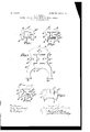
- Figure 1 shows one form of violin-bridge according to this invention.
- Figs. 2, 3, and 4 show bridges suitable for a violin, violoncello, and viola, respectively, the construction being one which is found to give very good results in practice; and
- Fig. 5 shows a modified construction of violin-bridge also according to this invention.
- A is what may be termed the supporting bar of the bridge, provided with the usual notches A for the strings.
- B represents feet adapted to lit and rest upon the belly of the instrument, and O is a cross-bar connecting such feet.
- the other end of the supporting-bar A is connected with the other foot B by another resilient portion D, and it is to be noted that owing to its shape the portion D supporting the upper or E string is so shaped that its stiffness is much less than that of the other resilient portion Dthat is to say, the part D acts as a weaker spring than the portion D. It will be readily understood that his graduated resiliency will act proportionally upon the inter- .mediate strings-namely, the D and the A strings.
- Flg. 2 shows a preferred construction of a violin-bridge according to this invention.
- the resilient portions or springs D D are made by cuts E E, extending from each side of the bridge in a horizontal direction about midway of its height. It will be noticed that in order to secure the necessary IIC difference in stiffness between the portions D and D the slot E is made of a greater length than the slot E. To still further increase the spring-like action of the portions D and D, openings F and F are formed above and beneath the line of the lateral slots. In the form shown in Fig. 1 the space between the resilient portions D and D is open; but it is advantageous in some cases to connect those portions by a cross-bar, as is shown at G in Fig. 2. This cross or connecting bar between the two resilient portions is found to prevent the loss of vibrations laterally or transversely without interfering with the efficient action of the two springs.
- the bridge illustrated in Fig. 3 is similar to that described with reference to Fig. 2, except that it is of a size and strength adapted for use with a Violoncello instead of a violin.
- the feet B are connected by legs B with the supporting arch or bar 0, which corresponds to the bar C in Figs. 1 and 2.
- Fig. 4 illustrates a bridge similar to the violin-bridge shown in Fig. 2, but of a size suitable for a viola.
- As'iTnilar type or improved bridge can be used for a double bass, the various parts being suitably proportioned to give the required gradations of resiliency to the various portions of the bridge which support the strings. It is to be noted that in bridges according to this invention the resiliency does not depend upon the feet and the arch connecting them, as is the case with cello and double-bass bridges of the usual type.
- Fig. 5 shows a violin-bridge in which the principle underlying this invention is carried out by means of a modified construction.
- each portion A of the bridge which carries a string is separated from the next portion by a slot A.
- These slots differ in depth, so that the portion A which carries the G-string is stiffer than the next portion carrying the D-string, and so on, the portion A supporting the E-string being separated by thelongest slot, and thereby made more resilient than the rest.
- the invention is not necessarily limited to instruments in which the strings are played by means of a bow, as in a violin, but the improved bridge, with portions having graduated resiliency to suit the strings which they support, may be fitted to any musical instrument which has a portion acting as a bridge for transmitting the vibrations of the strings to such instrument.
- a bridge for a stringed musical instrument having resilience increasing gradually from one side to the other.
- a bridge for stringed instruments conprising a string-bearing bar unsupported between its ends and a pair of resilient supporting members, one at each end of the bar, having difl'erent resiliency.
- a bridge for stringed musical instruments comprising a string-bearin g bar A, and members I) D supporting the bar at its ends, and differing in resiliency substantially as set forth.
- a bridge for a stringed musical instrument comprising a string-bearing bar A, members D D supporting the bar at its ends, and of different resiliency, and a connectingbar C between the members substantially as set forth.
Landscapes
- Physics & Mathematics (AREA)
- Engineering & Computer Science (AREA)
- Acoustics & Sound (AREA)
- Multimedia (AREA)
- Stringed Musical Instruments (AREA)
Description
No. 809,459. PATENTED JAN. 9, 1906. R. H. PAYNE.
BRIDGE FOR STRINGED MUSICAL INSTRUMENTS.
APPLICATION FILED DEG.5,1904
REGINALD HERBERT PAYNE, OF AYLESBURY, ENGLAND.
BRIDGE FOR STRINGED MUSICAL INSTRUMENTS.
Specification of Letters Patent.
Patented Jan. 9, 1906.
Application filed December 5, 1904. Serial No. 235,539.
To all whom it may concern:
Be it known that I, REGINALD HERBERT PAYNE, a subject of the King of England, residing at Aylesbury, Bucks, England, have invented certain new and useful Improvements in or Relating to Bridges for Stringed Musical Instruments, of which the following is a specification.
This invention relates to violins and like stringed musical instruments, and has for its object to modify the construction of the bridge upon which the strings rest, and thereby improve the tone of the instruments and the resonance of the strings.
A special feature of the invention is the graduation of the resiliency of the bridge or like portion to suit the nature of the vibrations which it has to transmit, strings giving rapid vibrations being supported by portions less stiff or more springy than those which act correspondingly for strings giving slower vibrations.
As heretofore constructed bridges for stringed instrumentssuch as violins, violas, violoncellos, and double basses-have been almost universally constructed on what is known as the Strad pattern, this bridge comprising a base-piece or arch, midway upon which it carried the portion upon which the strings rest, this portion being cut away so as to overhang at either side. A small opening, known as the kidney, is also usually made about the center'of the bridge. With this construction there is a certain amount of spring in the bridge at the points I where the strings giving the highest and lowest notes rest; but the intermediate strings lie upon a portion of the bridge whichis practically unyielding, and in consequence there is a certain muting effect when these strings are sounded as compared with those strings which rest upon a more yielding portion of the bridge.
It has been found by experiments that in order to get the full resonance of the strings it is necessary to carry them on a bridge having resilient portions differing in stiffness to suit the strings. Thus the stiflest or strongest resilient portion or spring should be beneath the string giving the lowest note and the weakest or lightest spring beneath the string giving the highest note, while the intermediate strings rest on portions of the bridge which yield to an extent correspondingly intermediate'between the stiffest and the weakest springs. From these experiments it has been found that the form of bridge which is commonly in use at the present day and is re versible and symmetrical is wrong in principle and that it is necessary, as is proposed according to this invention, to have a bridgewhich is non-reversible and specially made to give each string the support which is necessary in order to obtain the fullest effects therefrom.
According to this invention the bridge is so formed that, for example, in aviolin the G- string is carried upon a stiff spring, while the E-string rests upon a comparatively weak spring. The D and A strings rest upon a portion which lies intermediate between the stiffer and weaker springs, so that these strings lie upon a support which has such a resiliency as is adapted to enable the best results to be obtained from these strings.
In the accompanying drawings, Figure 1 shows one form of violin-bridge according to this invention. Figs. 2, 3, and 4 show bridges suitable for a violin, violoncello, and viola, respectively, the construction being one which is found to give very good results in practice; and Fig. 5 shows a modified construction of violin-bridge also according to this invention.
With reference first to Fig. 1, A is what may be termed the supporting bar of the bridge, provided with the usual notches A for the strings. B represents feet adapted to lit and rest upon the belly of the instrument, and O is a cross-bar connecting such feet. Connecting one end of the supporting-bar A, with the foot beneath it, is a curved piece D, forming a resilient portion or spring for the direct support of the lower or G string. The other end of the supporting-bar A is connected with the other foot B by another resilient portion D, and it is to be noted that owing to its shape the portion D supporting the upper or E string is so shaped that its stiffness is much less than that of the other resilient portion Dthat is to say, the part D acts as a weaker spring than the portion D. It will be readily understood that his graduated resiliency will act proportionally upon the inter- .mediate strings-namely, the D and the A strings.
Flg. 2 shows a preferred construction of a violin-bridge according to this invention.
In this form the resilient portions or springs D D are made by cuts E E, extending from each side of the bridge in a horizontal direction about midway of its height. It will be noticed that in order to secure the necessary IIC difference in stiffness between the portions D and D the slot E is made of a greater length than the slot E. To still further increase the spring-like action of the portions D and D, openings F and F are formed above and beneath the line of the lateral slots. In the form shown in Fig. 1 the space between the resilient portions D and D is open; but it is advantageous in some cases to connect those portions by a cross-bar, as is shown at G in Fig. 2. This cross or connecting bar between the two resilient portions is found to prevent the loss of vibrations laterally or transversely without interfering with the efficient action of the two springs.
The bridge illustrated in Fig. 3 is similar to that described with reference to Fig. 2, except that it is of a size and strength adapted for use with a Violoncello instead of a violin. The feet B are connected by legs B with the supporting arch or bar 0, which corresponds to the bar C in Figs. 1 and 2.
Fig. 4 illustrates a bridge similar to the violin-bridge shown in Fig. 2, but of a size suitable for a viola. As'iTnilar type or improved bridge can be used for a double bass, the various parts being suitably proportioned to give the required gradations of resiliency to the various portions of the bridge which support the strings. It is to be noted that in bridges according to this invention the resiliency does not depend upon the feet and the arch connecting them, as is the case with cello and double-bass bridges of the usual type.
Fig. 5 shows a violin-bridge in which the principle underlying this invention is carried out by means of a modified construction. In this form each portion A of the bridge which carries a string is separated from the next portion by a slot A. These slots, as shown in Fig. 5, differ in depth, so that the portion A which carries the G-string is stiffer than the next portion carrying the D-string, and so on, the portion A supporting the E-string being separated by thelongest slot, and thereby made more resilient than the rest.
It will be understood that the shape and thickness of the various parts of the bridge may be varied considerably without depart ing from the invention; also, the materials employed may be varied to suit requirements. WVith a bridge constructed as above described hard woods, such as ebony, may be utilized, as the bridge is in many cases lighter than the existing pattern. Such woods are unsuitable for use with the old form of bridge, as they mute the tone, but, on the contrary, when made according to the improved pattern the tone is found to be agreeable and soft. Further, the invention is not necessarily limited to instruments in which the strings are played by means of a bow, as in a violin, but the improved bridge, with portions having graduated resiliency to suit the strings which they support, may be fitted to any musical instrument which has a portion acting as a bridge for transmitting the vibrations of the strings to such instrument.
What I claim as my invention, and desire to secure by Letters Patent, is
1. A bridge for a stringed musical instrument having resilience increasing gradually from one side to the other.
2. A bridge for stringed instruments conprising a string-bearing bar unsupported between its ends and a pair of resilient supporting members, one at each end of the bar, having difl'erent resiliency.
3. A bridge for stringed musical instruments comprising a string-bearin g bar A, and members I) D supporting the bar at its ends, and differing in resiliency substantially as set forth.
4. A bridge for a stringed musical instrument comprising a string-bearing bar A, members D D supporting the bar at its ends, and of different resiliency, and a connectingbar C between the members substantially as set forth.
In testimony whereof I have signed my name to this specification in the presence of two subscribing witnesses.
ltlilGlNAhl) HERBERT PAYNE. WVitnesses HARRY B. BRIDGE, ARoHD. J. FRENCH.
Priority Applications (1)
| Application Number | Priority Date | Filing Date | Title |
|---|---|---|---|
| US23553904A US809459A (en) | 1904-12-05 | 1904-12-05 | Bridge for stringed musical instruments. |
Applications Claiming Priority (1)
| Application Number | Priority Date | Filing Date | Title |
|---|---|---|---|
| US23553904A US809459A (en) | 1904-12-05 | 1904-12-05 | Bridge for stringed musical instruments. |
Publications (1)
| Publication Number | Publication Date |
|---|---|
| US809459A true US809459A (en) | 1906-01-09 |
Family
ID=2877940
Family Applications (1)
| Application Number | Title | Priority Date | Filing Date |
|---|---|---|---|
| US23553904A Expired - Lifetime US809459A (en) | 1904-12-05 | 1904-12-05 | Bridge for stringed musical instruments. |
Country Status (1)
| Country | Link |
|---|---|
| US (1) | US809459A (en) |
-
1904
- 1904-12-05 US US23553904A patent/US809459A/en not_active Expired - Lifetime
Similar Documents
| Publication | Publication Date | Title |
|---|---|---|
| US7592529B2 (en) | Stringed musical instrument and structure of tailpiece unit used therein | |
| US1764679A (en) | Guitar | |
| US738811A (en) | Musical instrument. | |
| US685920A (en) | Musical instrument. | |
| US1755019A (en) | Musical instrument | |
| US809459A (en) | Bridge for stringed musical instruments. | |
| US3422715A (en) | Bridge construction in guitar-like instruments | |
| US2124439A (en) | Tailpiece for stringed musical instruments | |
| US2074982A (en) | Resilient bridge for stringed musical instruments | |
| US20050155480A1 (en) | Compound musical instrument string configuration and support system | |
| US2190475A (en) | Bridge for string instruments | |
| US2370460A (en) | Tone post for violins and similar musical instruments | |
| US494485A (en) | Attachment for guitars | |
| US1819796A (en) | Stringed musical instrument | |
| US627067A (en) | Mandolin | |
| US322925A (en) | Isaac hall | |
| US1329594A (en) | Violin | |
| US4512231A (en) | Violin construction | |
| US497939A (en) | John frederick charles abelspies | |
| US882702A (en) | Violin. | |
| US555651A (en) | Musical instrument | |
| US1431773A (en) | Stringed musical instrument | |
| US547150A (en) | monson | |
| RU2810610C1 (en) | Gusli | |
| US10127895B2 (en) | Contoured banjo bridge |