US809397A - Spoke-extractor. - Google Patents
Spoke-extractor. Download PDFInfo
- Publication number
- US809397A US809397A US20253304A US1904202533A US809397A US 809397 A US809397 A US 809397A US 20253304 A US20253304 A US 20253304A US 1904202533 A US1904202533 A US 1904202533A US 809397 A US809397 A US 809397A
- Authority
- US
- United States
- Prior art keywords
- spoke
- block
- hub
- bars
- extractor
- Prior art date
- Legal status (The legal status is an assumption and is not a legal conclusion. Google has not performed a legal analysis and makes no representation as to the accuracy of the status listed.)
- Expired - Lifetime
Links
- XEEYBQQBJWHFJM-UHFFFAOYSA-N Iron Chemical compound [Fe] XEEYBQQBJWHFJM-UHFFFAOYSA-N 0.000 description 2
- 239000002023 wood Substances 0.000 description 2
- 238000010276 construction Methods 0.000 description 1
- 229910052742 iron Inorganic materials 0.000 description 1
- 239000000463 material Substances 0.000 description 1
- 239000002184 metal Substances 0.000 description 1
- 229910052751 metal Inorganic materials 0.000 description 1
- 230000003313 weakening effect Effects 0.000 description 1
Images
Classifications
-
- B—PERFORMING OPERATIONS; TRANSPORTING
- B27—WORKING OR PRESERVING WOOD OR SIMILAR MATERIAL; NAILING OR STAPLING MACHINES IN GENERAL
- B27H—BENDING WOOD OR SIMILAR MATERIAL; COOPERAGE; MAKING WHEELS FROM WOOD OR SIMILAR MATERIAL
- B27H7/00—Manufacture of wood-rimmed wheels, e.g. cart wheels, steering wheels
Definitions
- My invention relates to an improved spokeextractor; and-I declare that the following is a full, clear, concise, and exact description thereof sufficient to enable one skilled in the art to make and use the same, reference being had to the accompanying drawings, in which like letters refer to like parts throughout.
- My device consists of a structure for withdrawing broken spokes from hubs or similar work and is constructed to employ force applied alternately in opposite directions, advantage being taken at each reversal of the results already accomplished.
- I have examined a large number of patents and dierent structures devised for this purpose, but observed nothing which applies force in this way and which is so simple and efficient in its operation as the device which I have invented. It is well known that a considerable degree of force is required to withdraw a spoke from a hub, as all means are employed to seat it firmly therein. It has often been attempted by means which employ force on a straight pull on the spoke. In my device, however, I employ a force applied on the side of the spoke, which is then changed on the reversal of the movement to an end pull, increasing by my device the leverage of each application.
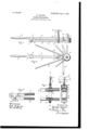
- Figure l is a side view of my device, showing it applied to a spoke and hub.
- Fig. 2 is a top view.
- Fig. 3 is a side view of a portion of the device in partial section.
- Fig. 4 is a section view on the line of Fig. 3, and
- Fig. 5 is a detail view of another portion of the structure.
- A represents a hub, and B spokes.
- C is one member of my device which is grooved through a portion of its length, as shown at c, Fig. 4, to receive the spoke, and at its outer end it is provided with handle C@ It may be made of any suitable material, although I employ wood for the purpose.
- D is a second member of my device, which is similarly grooved, as shown at d. It is not of the same length as the part C and at its outer end is connected with C by means of a bracket E, which is securely bolted or otherwise secured to part C.
- the bracket has depending portions E', each of which is provided wi'th bolt-holes e, so that C and D can be adjusted with greater or less closeness, according to the size of the spoke.
- C and D are surrounded by a stout metal collar F, to the lower part of which bar or arm D is secured by bolt d or otherwise.
- the arm C passes through the other end of the collar F and is provided with screw-seat c', which in turn is engaged by the screw G, operated by the thumb-piece G.
- the screw is threaded through the collar F, as indicated in Fig.
- H is a fulcrum block or wedge (shown in Fig. 2) and is to be crowded between the end of the bar C or of the bar D, as the case may be, when the device is applied to a spoke for extracting.
- the block may be made of iron or wood; but I prefer the latter, as it will not mar the hub.
- the bars are opened and thrust into the spoke, which is held between them substantially its entire length, the adjustment at e having been made to suit the case, so that if the spoke is splintered or broken the bars C and D bind it firmly, so that the force can be applied to the spoke for its entire length.
- the device is clamped onto the spoke a greater or less distance from the hub, which of course must be securely held in some way.
- clutching means comprising two bars adjustably pivotally connected toward their outer end and adjustably connected at their inner end, adjustable means provided between the end of the bars and the hub for applying side movement of the bars in extracting ⁇ the spoke, in combination, substantially as shown.
- a member provided'with means to clutch a spoke and extended substantially parallel with the spoke and adapted to receive and transmit an increased leverage applied thereto crosswise of the spoke and a block adapted to provide a Iulcrum for the said member, in swinging it to and iro across the normal line of the spoke.
- a member having means adjustable to clamp a spoke and being adapted to receive and apply to the spoke increased leverage applied to the said member beyond the end and transverse the line of said spoke and a hand-block adapted to be placed between the hub and the said clamping member, for applying side movement of the member in extracting the spoke.
- a member adapted to clutch various sizes of spokes lengthwise thereof and secure an extended leverage for the application of side pressure to the spoke and a fulcrum-block adapted to provide a fulcrum for the said member in swinging to and fro in extracting the spoke.
- a member adapted to clutch various sizes of spokes lengthwise thereof and extending beyond the end of the spoke to transmit side pressure to the spoke and a hand-block adapt-' In testimony whereof I affix my signature in presence of two witnesses.
Landscapes
- Engineering & Computer Science (AREA)
- Life Sciences & Earth Sciences (AREA)
- Manufacturing & Machinery (AREA)
- Mechanical Engineering (AREA)
- Wood Science & Technology (AREA)
- Forests & Forestry (AREA)
- Portable Nailing Machines And Staplers (AREA)
Description
No. 909,397. PATBNTBD JAN. 9, 1906. G. RAITHEL.
SPOKE EXTRAGTOR.
APPLICATION FILED APR.11. 1904.
W1 TNEssE.; IN1/ENT o NITED .STATES PATENT orrion SPOKE-EXTRACTOR.
Specification of Letters Patent.
Patented Jan. 9, 1906.
Application filed April l1, 1904. Serial Nol 202,533.
To o/,ZZ whom t may concern:
Be it known that I, GEORGE RAITHEL, a citizen of the United States, residing at Middleville, in the county ofI-Ierkimer and State of New York, have invented certain new and useful Improvements in Spoke-Extractors, of which the following is a specification, ref- .erence being had therein to the accompanying drawings.
My invention relates to an improved spokeextractor; and-I declare that the following is a full, clear, concise, and exact description thereof sufficient to enable one skilled in the art to make and use the same, reference being had to the accompanying drawings, in which like letters refer to like parts throughout.
My device consists of a structure for withdrawing broken spokes from hubs or similar work and is constructed to employ force applied alternately in opposite directions, advantage being taken at each reversal of the results already accomplished. I have examined a large number of patents and dierent structures devised for this purpose, but observed nothing which applies force in this way and which is so simple and efficient in its operation as the device which I have invented. It is well known that a considerable degree of force is required to withdraw a spoke from a hub, as all means are employed to seat it firmly therein. It has often been attempted by means which employ force on a straight pull on the spoke. In my device, however, I employ a force applied on the side of the spoke, which is then changed on the reversal of the movement to an end pull, increasing by my device the leverage of each application.
' Figure l is a side view of my device, showing it applied to a spoke and hub. Fig. 2 is a top view. Fig. 3 is a side view of a portion of the device in partial section. Fig. 4 is a section view on the line of Fig. 3, and Fig. 5 is a detail view of another portion of the structure.
Referring to the figures more in detail, A represents a hub, and B spokes.
C is one member of my device which is grooved through a portion of its length, as shown at c, Fig. 4, to receive the spoke, and at its outer end it is provided with handle C@ It may be made of any suitable material, although I employ wood for the purpose. D is a second member of my device, which is similarly grooved, as shown at d. It is not of the same length as the part C and at its outer end is connected with C by means of a bracket E, which is securely bolted or otherwise secured to part C. This bracket 1s shown as consisting of two parts, one on each side of the member or arm C and provided with nubs e for its more secure mounting. It may be made in any suitable form and manner, care to be given, however, to its mounting, so as to secure the greatest strength without weakening arm C. The bracket has depending portions E', each of which is provided wi'th bolt-holes e, so that C and D can be adjusted with greater or less closeness, according to the size of the spoke. At the other end parts C and D are surrounded by a stout metal collar F, to the lower part of which bar or arm D is secured by bolt d or otherwise. The arm C passes through the other end of the collar F and is provided with screw-seat c', which in turn is engaged by the screw G, operated by the thumb-piece G. The screw is threaded through the collar F, as indicated in Fig. 4, the purpose of which arrangement is to permit the bar C to be screwed down in close contact to hold the spoke between itself and bar D. To make the grip of bars C and D on the spoke more secure, -I provide on the opposite faces of bars C and D the toothed or serrated clips g g', which may have some such construction as indicated, their function being to tightly hold the spoke when bars C and D are brought together against it.
H is a fulcrum block or wedge (shown in Fig. 2) and is to be crowded between the end of the bar C or of the bar D, as the case may be, when the device is applied to a spoke for extracting. The block may be made of iron or wood; but I prefer the latter, as it will not mar the hub. In operation the bars are opened and thrust into the spoke, which is held between them substantially its entire length, the adjustment at e having been made to suit the case, so that if the spoke is splintered or broken the bars C and D bind it firmly, so that the force can be applied to the spoke for its entire length. The device is clamped onto the spoke a greater or less distance from the hub, which of course must be securely held in some way. Pressure is then exerted on handle C up or down. This may be applied two or three times, if desired, before'the fulcrum-block is used; but thereafter when the handle has been pushed down the fulcrum-block is inserted between the end of IOO TIO
bar C and the hub, as shown in Fig. 1, and opposite pressure is applied to the handle, the eiiect of which is by long purchase to pull the spoke outward but slightly off a straight pull. The handle can then be pressed down again and the block crowded in and then pulled up, as before. This operation can be repeated with the ulcrum-block on the same side of the spoke, or, if desired, two blocks can be used or one alternately on either side.
It will be evident that my device can be made in a variety of ways so as to employ the same principle of operation, and I do not limit myself to the particulars illustrated and described.
Having described my invention, what I claim as new, and desire to secure by Letters Patent, isl l. In a device of the character described, means provided to clutch a spoke, said means provided with an outwardly-extended handle and a block adapted to provide a l'ulcrum for the handle in its operation to and 'fr0 across the normal line of the spoke, substantially as described.
2. In a spoke-extractor, clutching means comprising two bars adjustably pivotally connected toward their outer end and adjustably connected at their inner end, adjustable means provided between the end of the bars and the hub for applying side movement of the bars in extracting` the spoke, in combination, substantially as shown.
3. In a device of the character described, a member provided'with means to clutch a spoke and extended substantially parallel with the spoke and adapted to receive and transmit an increased leverage applied thereto crosswise of the spoke and a block adapted to provide a Iulcrum for the said member, in swinging it to and iro across the normal line of the spoke.
4. In a device of the character described, a member having means adjustable to clamp a spoke and being adapted to receive and apply to the spoke increased leverage applied to the said member beyond the end and transverse the line of said spoke and a hand-block adapted to be placed between the hub and the said clamping member, for applying side movement of the member in extracting the spoke.
5. In a device oi the character described,
a member adapted to clutch various sizes of spokes lengthwise thereof and secure an extended leverage for the application of side pressure to the spoke and a fulcrum-block adapted to provide a fulcrum for the said member in swinging to and fro in extracting the spoke.
6. In a device of the character described, a member adapted to clutch various sizes of spokes lengthwise thereof and extending beyond the end of the spoke to transmit side pressure to the spoke and a hand-block adapt-' In testimony whereof I affix my signature in presence of two witnesses.
GEORGE' RAITHEL. Witnesses:
MARINUs HERFKENS, FRED JONES.
Priority Applications (1)
| Application Number | Priority Date | Filing Date | Title |
|---|---|---|---|
| US20253304A US809397A (en) | 1904-04-11 | 1904-04-11 | Spoke-extractor. |
Applications Claiming Priority (1)
| Application Number | Priority Date | Filing Date | Title |
|---|---|---|---|
| US20253304A US809397A (en) | 1904-04-11 | 1904-04-11 | Spoke-extractor. |
Publications (1)
| Publication Number | Publication Date |
|---|---|
| US809397A true US809397A (en) | 1906-01-09 |
Family
ID=2877878
Family Applications (1)
| Application Number | Title | Priority Date | Filing Date |
|---|---|---|---|
| US20253304A Expired - Lifetime US809397A (en) | 1904-04-11 | 1904-04-11 | Spoke-extractor. |
Country Status (1)
| Country | Link |
|---|---|
| US (1) | US809397A (en) |
-
1904
- 1904-04-11 US US20253304A patent/US809397A/en not_active Expired - Lifetime
Similar Documents
| Publication | Publication Date | Title |
|---|---|---|
| US904863A (en) | Wire clamp or grip. | |
| US809397A (en) | Spoke-extractor. | |
| US757195A (en) | Rod-grasping arm or handle. | |
| US883820A (en) | Cant-hook. | |
| US1154916A (en) | Cable-clamp. | |
| US711443A (en) | Handle for operating cycle-brakes. | |
| US981562A (en) | Wire-clamp. | |
| US1383123A (en) | Wsestch | |
| US857717A (en) | Rope-thimble. | |
| US858965A (en) | Clamping device. | |
| US713135A (en) | Shaft-coupling. | |
| US820866A (en) | Combined pipe clamp and wrench. | |
| US634175A (en) | Wrench. | |
| US770637A (en) | Belt tightener or stretcher | |
| US695063A (en) | Mop-head. | |
| US894104A (en) | Column-clamp. | |
| US937636A (en) | Fruit-jar wrench. | |
| US554157A (en) | Wrench | |
| US1031306A (en) | Clamp. | |
| US902305A (en) | Wrench. | |
| US594563A (en) | Pipe-wrench | |
| US719960A (en) | Pipe-wrench. | |
| US889250A (en) | Belt-stretcher. | |
| US1153070A (en) | Extractor. | |
| US381213A (en) | Wrench |