US809333A - Cam-movement explosive-engine. - Google Patents
Cam-movement explosive-engine. Download PDFInfo
- Publication number
- US809333A US809333A US14008703A US1903140087A US809333A US 809333 A US809333 A US 809333A US 14008703 A US14008703 A US 14008703A US 1903140087 A US1903140087 A US 1903140087A US 809333 A US809333 A US 809333A
- Authority
- US
- United States
- Prior art keywords
- cylinder
- reciprocating
- motion
- rotatory
- engine
- Prior art date
- Legal status (The legal status is an assumption and is not a legal conclusion. Google has not performed a legal analysis and makes no representation as to the accuracy of the status listed.)
- Expired - Lifetime
Links
- 239000002360 explosive Substances 0.000 description 13
- 239000000203 mixture Substances 0.000 description 12
- 239000012530 fluid Substances 0.000 description 9
- 230000000737 periodic effect Effects 0.000 description 7
- 230000001131 transforming effect Effects 0.000 description 7
- 241000005139 Lycium andersonii Species 0.000 description 4
- 238000006243 chemical reaction Methods 0.000 description 3
- 238000002485 combustion reaction Methods 0.000 description 3
- 230000006835 compression Effects 0.000 description 3
- 238000007906 compression Methods 0.000 description 3
- 238000001816 cooling Methods 0.000 description 2
- 230000000694 effects Effects 0.000 description 2
- XLYOFNOQVPJJNP-UHFFFAOYSA-N water Substances O XLYOFNOQVPJJNP-UHFFFAOYSA-N 0.000 description 2
- 229910001018 Cast iron Inorganic materials 0.000 description 1
- 238000005266 casting Methods 0.000 description 1
- 230000015556 catabolic process Effects 0.000 description 1
- 238000010276 construction Methods 0.000 description 1
- 230000006378 damage Effects 0.000 description 1
- 238000010438 heat treatment Methods 0.000 description 1
- 230000001050 lubricating effect Effects 0.000 description 1
- 238000005461 lubrication Methods 0.000 description 1
- 230000001550 time effect Effects 0.000 description 1
Images
Classifications
-
- F—MECHANICAL ENGINEERING; LIGHTING; HEATING; WEAPONS; BLASTING
- F02—COMBUSTION ENGINES; HOT-GAS OR COMBUSTION-PRODUCT ENGINE PLANTS
- F02B—INTERNAL-COMBUSTION PISTON ENGINES; COMBUSTION ENGINES IN GENERAL
- F02B75/00—Other engines
- F02B75/02—Engines characterised by their cycles, e.g. six-stroke
- F02B2075/022—Engines characterised by their cycles, e.g. six-stroke having less than six strokes per cycle
- F02B2075/025—Engines characterised by their cycles, e.g. six-stroke having less than six strokes per cycle two
Definitions
- My invention in explosive-engines relates to .internal-combustion motors of the rapid combustion or explosive type, and has particular reference to a means for converting the reciprocating movement of the power-impressed kinematic member into a rotatory movement of the driven member, and vice versa.
- the objects of my invention are, first, to provide a more compact and simple means in the conversion of motion for engines of this character and those in Vogue previous to my invention of which I am at present aware, and, second, to reduce the weight of motors of this character in proportion to the amount of horse-power capacitythat the same isdesigned to develop and at the same time effect such changes in the construction which will condense the parts into a more compact form than those employing the crank and connecting-rod principle in the conversion of the motion of the reciprocating element.
- A constitutes the framework of the engine, which I prefer to construct of cast-iron; B, the fly-wheel or rotatory member; C, the cylinder or reciprocating element, and D the piston.
- the piston y D is fixed to the framework by means of a head E, which is turned up true with the body F of the piston and is shouldered into a bored recess'G and secured rigidly in position by bolts H, while the cylinder C is adapted to vibrate to and fro, so that a plane within the cylinder indicated by the dotted line I during an inward stroke of the cylinder C will fall upon the end of the piston and upon an outward stroke of the cylinder the head J of the cylinder will move to the position of the dotted line K.
- I provide two guiderods L and L', bolted to the head E and secured by a screw-thread to a ring M, which pass through perforations m m in a trunked piston-head O, which is formed integral with the cylinder C, in a manner so as to form a cross-head sliding upon the guide-rods L L
- the ring M is in turn secured to the framework against rotation by a series of bolts M', one of which in the drawing suffices to illustrate their arrangement, and is drawn up against a shoulder formed in the framework, as shown, upon tightening the bolts L and L.
- I provide the usual babbitted bearing N, secured to the framework in a customary manner by recesses and bolts, as illustrated.
- I In order to convert the motion of the vibrating cylinder C into a movement of rota- Y tion at the fly-wheel, I form a diagonally-cut groove P upon the perimeter of the cylinder C, so as to form a sort of track or channel around the same obliquely to the axis thereof, as indicated by the dotted lines, and I prefer to form this groove at what is known in mechanics as the critical angle with the axis of reciprocation, which is the diagonal of a square contained between the two extreme diametrically opposite points of the maj or axis of the ellipse thus formed and the opposite sides of the cylinder.
- the major axis of the ellipse would then form the hypotenuse of a right isosceles triangle with two sides of the said angle, having its base along a line on the periphery of the cylinder and parallel with the axis of the same and the other side of the said angle being a perpendicular dropped from the origin of the angle at a diametrically opposite point in the cylinder upon the said base.
- the ellipse being in a diagonal plane through la section of a cylinder when opened out upon a plane surface would form a figure what is known in geometery as a sinusoid.
- This groove in mechanics is known as a cam-groove, and its importance when its function is considered in connection with the iy-wheel B and the conical roller p as the kinematic instrumentalities to effect a mutual conversion of motion of TOO the reciprocating element C and the rotating member B will be manifest, as will be understood by the hereinafter description relative thereto.
- the roller p is adapted to roll upon the edge n and be just clear of the edge n of the grooved track P when the cylinder C is moved outward or into the position of the dotted line K, which would be the effect of an internal pressure of the working fluid in the combustion-chamber, acting between the inner end wall or head J and the piston D, when the roller p would be brought into contact with the edge n of the track or groove P in a manner so as to translate its movement into one of rotation in the fly-wheel B, and by the time the cylinder C has reached the outward limit of its working stroke, so that the cylinder-head J shall have coincided with the dotted line K, the roller p will have been brought to the apex of the elliptical curved track P, and, as shown in the drawing, the cylinder C is approximately at the terminus of its outward working stroke and will then be on dead-center, and due to the inertia of the fiy-wheel B by the movement imparted to the same by the outward stroke of the
- the cylinder C will have what is known in mechanics as a simple periodic movement, in which case, however, the contacting edges n and n of the elliptical track or groove will alternate during each half-revolution with the diametrically opposite points of the roller p at the instant of reversal of the reciprocating cylinder C-that is to say, a change in the direction of motion of the cylinder C during its reciprocation by a constant rotatory member will change the algebraic sign of motion of the coacting surfaces between the walls or edges n n of the elliptical cam-groove P and corresponding points of contact upon the perimeter of the revolving follower p', which would give rise to hammering opposite faces of the follower and edges n n of the groove P, resulting finally in the break-down and destruction of the kinematic translating instrumentalities or parts thus coacting
- the said fuel-supply port or inlet-passage 1 passes through the water-jacket d and is illustrated in the drawings as broken away about midway of its length, showing the continuous annular water-jacket d, which is interrupted for a portion of its circumference by the fuel-supply port or inlet-passage r.
- the exhaust-valve R will be reciprocated, opening during a period occupied by the movement of the rotatory meniber B or fly-wheel and closed by a retractingspring, the said opening being effected by means of the cam R, tappet-bar, and roller R, and tappet S, so as to admit the products of combustion into the interior T of the piston, and finally out of the lateral exhaustopening T.
- I provide a water-jacket d, annularly formed, as aforesaid, and having ports S and having a sliding connection for a length coincident with the stroke of the cylinder with a stationary water port or duct t and a water-inlet-pipe connection t', made integral with the casting E, which is adapted to convey the water for cooling the cylinder C through a port s or water-jacket d and thence to a diametrically oppositely situated corresponding outlet-duct, ports, and passage-ways and outlet connection t".
- I am enabled ⁇ to cool both the piston and the cylinder from a xed point at the rear of the motor.
- a reciprocating explosive engine wherein the motion of thereciprocating element actuated by an energized power medium, is adapted to be translated into a rotary motion at its fly-wheel, a kinematic connection between the fiy-wheel and the reciprocating element located within the hub of the fly-wheel,for converting the motion of the reciprocating element into a relatively constant rotatory motion of the fiy-wheel and conversely for transforming a constant rotatory motion of the fiy-wheel into a periodic reciprocating motion of the reciprocating element, together with suitable valve mechanism for controlling the working fiuid for said engine, actuated by said fiy-wheel, substantially as described.
- a kinematicconnection between the fiy-wheel and the reciprocating element located within the hub of the fly-wheel for converting the motion of the reciprocating element into a relatively constant rotatory motion of the fly-wheel and conversely for transforming a constant rotatory motion of the iiy-'wheel into a periodic reciprocating motion of the reciprocating element, a circulating fluid between said reciprocating element and saidfly-wheel, and a valve for controlling the working fluid for said engine, together with means coacting between said fiy-wheel and said valve for actuating the latter upon the rotation of the said fly-wheel substantially as described.
- a kinematic connection between the reciprocating power element and the rotatory member located at a point radiating froin the axis of rotation of the rotatory member, for translating the motion of the reciprocating power element into a relatively constant rotatory motion of the rotatory member and conversely for transforming a constant rotatory motion of the rotatory member into a periodic reciprocating motion of the reciprocating power element, a circulating fluid between said reciprocating power element and said rotatory member, a
- an explosive -engine comprising a combustion-chamber having a reciprocating power element actuated by an explosive mixture confined in said combustion-chamber and a rotatory member adapted to revolve about said reciprocating power element, a kinematic connection between the reciprocating power element and the rotatory mem- ISO ber located at a point radiating from the axis olE rotation of the rotatory member and exterior to said cylinder, for translating the motion of the reciprocating power element into a relatively constant rotatory motion of the rotatory member and conversely for transforming a constant rotatory motion ol the rotatory member into a periodic motion of the reciprocating power element, a circulating Huid between said reciprocating power element and said rotatory member, a reciprocating valve for controlling the working vfluid for said engine, together with means coacting between said rotatory member and lsaid valve for actuating the latter upon the rotation of the said rotatory member and means located within the cylinder for igniting said explosive mixture
- an explosive-engine comprising a combustion-chamber having'a reciprocating power element actuated by an explosive mixture confined in said combustion-chamber and a rotatory member adapted to revolve about said reciprocating power element, a kinematic connection between the reciprocating power element and the rotatory mem- ⁇ ber located in an arc radiating from the axis vol" rotation of the rotatory member and concentric with the exterior of said cylinder, for translating the motion of the reciprocating power element into a relatively constant rotatory motion of the rotatory member and conversely for transforming a constant rotatory motion of the rotatory member into a periodic reciprocating motion of the reciprocating power element, a circulating iluid between said reciprocating power element and said rotatory member, a reciprocating valve for controlling the working fluid for said engine, together with means coacting between said rotatory member and said valve for actuating the latter upon the rotation of the said rotatory member and means located within the cylinder for igniting the explosive mixture.
- an explosive-engine comprising a combustion-chamber having a reciprocating power element actuated by an explosive mixture con'lined within said chamber and arctatory member adapted to revolve about said reciprocating power element, said reciprocating power element adapted to vibrate along an axial line coincident with the axis of rotation of the rotatory member, a kinematic connection between the reciprocating power element and the rotatory member, for translating the motion ofthe reciprocating power element into a relatively constant rotatory motion of the rotatory member and conversely ⁇ for transforming a constant rotatory motion PHILIP K. STERN.
Landscapes
- Engineering & Computer Science (AREA)
- Chemical & Material Sciences (AREA)
- Combustion & Propulsion (AREA)
- Mechanical Engineering (AREA)
- General Engineering & Computer Science (AREA)
- Transmission Devices (AREA)
Description
N0. 809,333. f PATENTED JAN. 9, 1906.
P. K. STERN.'
CAM MOVEMENT EXPLOSIVE ENGINE.
APPLICATION FIIED JAN. 22. 1903.
.h A H1 V n lun/lullin' llulllllllllllll.Illl'lllllllllllllll WgTNEEEESL NVENTUR mmm AUNITED STATES PATENT OFFICE..
CANI-MOVEMENT EXPLOSlVE-ENGINE.
Specification of Letters Patent.
Patented Jan. 9, 1906.
Application iiled January 22. 1903. Serial No. 140,087.
T0 all r11/"wm it may con/cern:
Be it known that I, PHILIP K. STERN, a citizen of the United States, residing in the city of New York, in the county and State of New York, have invented certain new and useful Improvements in Cam-Movement Explosive-Engines, of which the following is a specification.
My invention in explosive-engines relates to .internal-combustion motors of the rapid combustion or explosive type, and has particular reference to a means for converting the reciprocating movement of the power-impressed kinematic member into a rotatory movement of the driven member, and vice versa.
The objects of my invention are, first, to provide a more compact and simple means in the conversion of motion for engines of this character and those in Vogue previous to my invention of which I am at present aware, and, second, to reduce the weight of motors of this character in proportion to the amount of horse-power capacitythat the same isdesigned to develop and at the same time effect such changes in the construction which will condense the parts into a more compact form than those employing the crank and connecting-rod principle in the conversion of the motion of the reciprocating element.
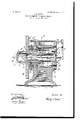
In carrying out my invention I have selected that type known as the two-cycle rear compression explosive engine, to apply my principles, the different characteristic features being clearly illustrated in the figure, the same being a vertical sectional view taken through the center of the engine, so that one-half of the same nearest the observer is removed.
The different parts are identified by different characters of reference; but the same parts are designated by similar characters.
A constitutes the framework of the engine, which I prefer to construct of cast-iron; B, the fly-wheel or rotatory member; C, the cylinder or reciprocating element, and D the piston. Itwill be observed that the piston y D is fixed to the framework by means of a head E, which is turned up true with the body F of the piston and is shouldered into a bored recess'G and secured rigidly in position by bolts H, while the cylinder C is adapted to vibrate to and fro, so that a plane within the cylinder indicated by the dotted line I during an inward stroke of the cylinder C will fall upon the end of the piston and upon an outward stroke of the cylinder the head J of the cylinder will move to the position of the dotted line K. In order to restrain the cylinder C against rotation, I provide two guiderods L and L', bolted to the head E and secured by a screw-thread to a ring M, which pass through perforations m m in a trunked piston-head O, which is formed integral with the cylinder C, in a manner so as to form a cross-head sliding upon the guide-rods L L The ring M is in turn secured to the framework against rotation by a series of bolts M', one of which in the drawing suffices to illustrate their arrangement, and is drawn up against a shoulder formed in the framework, as shown, upon tightening the bolts L and L. To support the fly-wheel B so that'it will revolve about the cylinder C Without undue friction between the adjacent surfaces of the hub I) of the ily-wheel and the outer perimeter of the cylinder, I provide the usual babbitted bearing N, secured to the framework in a customary manner by recesses and bolts, as illustrated. i In order to convert the motion of the vibrating cylinder C into a movement of rota- Y tion at the fly-wheel, I form a diagonally-cut groove P upon the perimeter of the cylinder C, so as to form a sort of track or channel around the same obliquely to the axis thereof, as indicated by the dotted lines, and I prefer to form this groove at what is known in mechanics as the critical angle with the axis of reciprocation, which is the diagonal of a square contained between the two extreme diametrically opposite points of the maj or axis of the ellipse thus formed and the opposite sides of the cylinder. The major axis of the ellipse would then form the hypotenuse of a right isosceles triangle with two sides of the said angle, having its base along a line on the periphery of the cylinder and parallel with the axis of the same and the other side of the said angle being a perpendicular dropped from the origin of the angle at a diametrically opposite point in the cylinder upon the said base. The ellipse being in a diagonal plane through la section of a cylinder when opened out upon a plane surface would form a figure what is known in geometery as a sinusoid. This groove in mechanics is known as a cam-groove, and its importance when its function is considered in connection with the iy-wheel B and the conical roller p as the kinematic instrumentalities to effect a mutual conversion of motion of TOO the reciprocating element C and the rotating member B will be manifest, as will be understood by the hereinafter description relative thereto.
Secured to the fly-wheel B is a radially-disposed wrist-pin p and the conical roller or follower p aforesaid, which is a truncated cone, revolubly mounted on said wrist-pin p, having the origin of its apex at a point within the axis of rotation of the cylinder C and vertically over the axis of the said wrist-pin. The roller p is adapted to roll upon the edge n and be just clear of the edge n of the grooved track P when the cylinder C is moved outward or into the position of the dotted line K, which would be the effect of an internal pressure of the working fluid in the combustion-chamber, acting between the inner end wall or head J and the piston D, when the roller p would be brought into contact with the edge n of the track or groove P in a manner so as to translate its movement into one of rotation in the fly-wheel B, and by the time the cylinder C has reached the outward limit of its working stroke, so that the cylinder-head J shall have coincided with the dotted line K, the roller p will have been brought to the apex of the elliptical curved track P, and, as shown in the drawing, the cylinder C is approximately at the terminus of its outward working stroke and will then be on dead-center, and due to the inertia of the fiy-wheel B by the movement imparted to the same by the outward stroke of the cylinder C the roller p will be carried past the point of dead-center in the ellipticallyformed track or groove P on the opposite side of the diameter of the cylinder C, and the same will be returned to its original position. Thus it will be seen that for a complete revolution of the iiy-wheel B a complete reciprocation is given to the cylinder C. That space of the cylinder contained between the piston D and the inner wall of the cylinder-head J and the inner cylindrical surface of the cylinder between these positions constitutes at any instance the combustionchamber. If a belt be wrapped around the periphery of the fly-wheel B and the latter be driven by a source of continuous motion, it would be noted that the cylinder C will have what is known in mechanics as a simple periodic movement, in which case, however, the contacting edges n and n of the elliptical track or groove will alternate during each half-revolution with the diametrically opposite points of the roller p at the instant of reversal of the reciprocating cylinder C-that is to say, a change in the direction of motion of the cylinder C during its reciprocation by a constant rotatory member will change the algebraic sign of motion of the coacting surfaces between the walls or edges n n of the elliptical cam-groove P and corresponding points of contact upon the perimeter of the revolving follower p', which would give rise to hammering opposite faces of the follower and edges n n of the groove P, resulting finally in the break-down and destruction of the kinematic translating instrumentalities or parts thus coacting.
In order to maintain a constant pressure on but one face n of the cam-groove P, the algebraio sign of the impressed power should be changed during each half-revolution, and to this end I have provided a means whereby during one half-revolution the cylinder C is moved outward by a positive force due to the power fluid of the cylinder, and the return stroke of the same is actuated by a negative force with respect to the cylinder C or by the inertia of the rotating element or fly-wheel B, thus satisfying the conditions requisite for a continuity of contact between the same edges or surfaces of the follower p and wall n of the cam-groove P, and in order to carry out this principle I have adapted a combustion-motor operating under what is known as the two-cycle principle in the manner following: As the cylinder C is moving inward by the inertia of the fly-wheel B, the latter being previously set into motion, the aspirating-space Q, contained between the ring M and truncated piston-head D, will have its capacity increased sufficiently to allow the inhalation of the combustible mixture from a suitable supply-tank or carbureter to pass by way of the intake-pipe g and intake-valve g to the inhalation-space Q, and upon an outward movement of the cylinder C the combustible mixture taken into the inhalation-space Q will be compressd between the truncated piston O, which is made tight by packing-rings, as shown, and the annular abutment-ring M is likewise made tight, seating the intake-valve q' and unseating the check-valve q, allowing the mixture under compression to pass by way of the fuelsupply port or inlet-passage r and spring-retracted inlet-valve r to the combustion-chamber. The said fuel-supply port or inlet-passage 1 passes through the water-jacket d and is illustrated in the drawings as broken away about midway of its length, showing the continuous annular water-jacket d, which is interrupted for a portion of its circumference by the fuel-supply port or inlet-passage r. Upon the return stroke of the cylinder C the mixture will be compressed by the decrease in capacity of the cylinder C due to the piston D, and the inlet-valve r will be iirmly seated, and upon the compression of the mixture to an extent commensurate with the capacity of the clearance-space contained between the dotted line l and inlet-valve r the same will be ignited in the usual manner by means of the ignition-plug B and the usual concomitant mechanism, and the engine will receive its -first working stroke. At about the extremity of the outward working stroke IOO IIO
ISO
of the cylinder C the exhaust-valve R will be reciprocated, opening during a period occupied by the movement of the rotatory meniber B or fly-wheel and closed by a retractingspring, the said opening being effected by means of the cam R, tappet-bar, and roller R, and tappet S, so as to admit the products of combustion into the interior T of the piston, and finally out of the lateral exhaustopening T.
` In order to prevent undue heating of the cylinder, I provide a water-jacket d, annularly formed, as aforesaid, and having ports S and having a sliding connection for a length coincident with the stroke of the cylinder with a stationary water port or duct t and a water-inlet-pipe connection t', made integral with the casting E, which is adapted to convey the water for cooling the cylinder C through a port s or water-jacket d and thence to a diametrically oppositely situated corresponding outlet-duct, ports, and passage-ways and outlet connection t". By this manner of cooling I am enabled` to cool both the piston and the cylinder from a xed point at the rear of the motor. During the rearward movement of the truncated pistonhead O the volume of air contained within the space L i s permitted to escape through the openings U and V, thereby relieving the dead stroke of the cylinder C of undue work.
In order to provide for effective lubrication of the different wearing parts, I have provided lubricating channels or ducts, as shown.
Having fully described the nature of my invention, whereby those who are skilled in the art to which the saine appertains could construct and operate the saine, I claim as new and desire to secure by Letters Ia'tent of the United Statesl. In a reciprocating explosive engine, wherein the motion of thereciprocating element actuated by an energized power medium, is adapted to be translated into a rotary motion at its fly-wheel, a kinematic connection between the fiy-wheel and the reciprocating element located within the hub of the fly-wheel,for converting the motion of the reciprocating element into a relatively constant rotatory motion of the fiy-wheel and conversely for transforming a constant rotatory motion of the fiy-wheel into a periodic reciprocating motion of the reciprocating element, together with suitable valve mechanism for controlling the working fiuid for said engine, actuated by said fiy-wheel, substantially as described.
2. In a reciprocating explosive engine, wherein the motion of the reciprocating element actuated by an energized power medium is adapted to be translated into a rotary motion at its fiy-wheel, a kinematicconnection between the fiy-wheel and the reciprocating element located within the hub of the fly-wheel, for converting the motion of the reciprocating element into a relatively constant rotatory motion of the fly-wheel and conversely for transforming a constant rotatory motion of the iiy-'wheel into a periodic reciprocating motion of the reciprocating element, a circulating fluid between said reciprocating element and saidfly-wheel, and a valve for controlling the working fluid for said engine, together with means coacting between said fiy-wheel and said valve for actuating the latter upon the rotation of the said fly-wheel substantially as described.
3. In an explosive-engine having areciprocating power element actuated by an energized power medium and a rotatory member therefor,a kinematic connection between the reciprocating power element and tlie'rotatory member located at a point radiating from the axis of rotation of the rotatory member, for translating the motion of the reciprocating power element into a relatively constant rotatory motion of the rotatory member and conversely for transforming a constant rotatory motion of the rotatory memberinto a periodic reciprocating motion of the reciprocating power element, a circulating fluid between the said reciprocating power element and said rotatory member, and a reciprocating valve for controlling the working fluid for the said engine, together with means coacting between said rotatory member and said valve for actuating the latter upon the rotation of the said rotatory member; substantially as described.
4. In an explosive-engine having a reciprocating power element actuated by an explosive mixture and a rotatory member therefor adapted to revolve about said reciprocating power element, a kinematic connection between the reciprocating power element and the rotatory member located at a point radiating froin the axis of rotation of the rotatory member, for translating the motion of the reciprocating power element into a relatively constant rotatory motion of the rotatory member and conversely for transforming a constant rotatory motion of the rotatory member into a periodic reciprocating motion of the reciprocating power element, a circulating fluid between said reciprocating power element and said rotatory member, a
IOO
IIS
reciprocating valve for controlling the working fluid for said engine, together with means coacting between said rotatory member and said valve for actuating the latter upon the rotation of the said rotatory member and means for igniting said explosive mixture.
5. In an explosive -engine comprising a combustion-chamber having a reciprocating power element actuated by an explosive mixture confined in said combustion-chamber and a rotatory member adapted to revolve about said reciprocating power element, a kinematic connection between the reciprocating power element and the rotatory mem- ISO ber located at a point radiating from the axis olE rotation of the rotatory member and exterior to said cylinder, for translating the motion of the reciprocating power element into a relatively constant rotatory motion of the rotatory member and conversely for transforming a constant rotatory motion ol the rotatory member into a periodic motion of the reciprocating power element, a circulating Huid between said reciprocating power element and said rotatory member, a reciprocating valve for controlling the working vfluid for said engine, together with means coacting between said rotatory member and lsaid valve for actuating the latter upon the rotation of the said rotatory member and means located within the cylinder for igniting said explosive mixture.
6. In an explosive-engine, comprising a combustion-chamber having'a reciprocating power element actuated by an explosive mixture confined in said combustion-chamber and a rotatory member adapted to revolve about said reciprocating power element, a kinematic connection between the reciprocating power element and the rotatory mem- `ber located in an arc radiating from the axis vol" rotation of the rotatory member and concentric with the exterior of said cylinder, for translating the motion of the reciprocating power element into a relatively constant rotatory motion of the rotatory member and conversely for transforming a constant rotatory motion of the rotatory member into a periodic reciprocating motion of the reciprocating power element, a circulating iluid between said reciprocating power element and said rotatory member, a reciprocating valve for controlling the working fluid for said engine, together with means coacting between said rotatory member and said valve for actuating the latter upon the rotation of the said rotatory member and means located within the cylinder for igniting the explosive mixture.
7. In an explosive-engine comprising a combustion-chamber having a reciprocating power element actuated by an explosive mixture con'lined within said chamber and arctatory member adapted to revolve about said reciprocating power element, said reciprocating power element adapted to vibrate along an axial line coincident with the axis of rotation of the rotatory member, a kinematic connection between the reciprocating power element and the rotatory member, for translating the motion ofthe reciprocating power element into a relatively constant rotatory motion of the rotatory member and conversely `for transforming a constant rotatory motion PHILIP K. STERN.
Witnesses I-I. M. MAHER, WILLIAM PAx'roN.
Priority Applications (1)
| Application Number | Priority Date | Filing Date | Title |
|---|---|---|---|
| US14008703A US809333A (en) | 1903-01-22 | 1903-01-22 | Cam-movement explosive-engine. |
Applications Claiming Priority (1)
| Application Number | Priority Date | Filing Date | Title |
|---|---|---|---|
| US14008703A US809333A (en) | 1903-01-22 | 1903-01-22 | Cam-movement explosive-engine. |
Publications (1)
| Publication Number | Publication Date |
|---|---|
| US809333A true US809333A (en) | 1906-01-09 |
Family
ID=2877814
Family Applications (1)
| Application Number | Title | Priority Date | Filing Date |
|---|---|---|---|
| US14008703A Expired - Lifetime US809333A (en) | 1903-01-22 | 1903-01-22 | Cam-movement explosive-engine. |
Country Status (1)
| Country | Link |
|---|---|
| US (1) | US809333A (en) |
-
1903
- 1903-01-22 US US14008703A patent/US809333A/en not_active Expired - Lifetime
Similar Documents
| Publication | Publication Date | Title |
|---|---|---|
| EP0799371B1 (en) | Axial piston rotary engine | |
| USRE30565E (en) | Internal combustion engine and operating cycle | |
| US3408991A (en) | Oscillating machine | |
| KR20000029881A (en) | Improvements in axial piston rotary engines | |
| US3356080A (en) | Internal combustion engine with wobble plate shaft drive | |
| US5894820A (en) | Engine for converting linear motion into rotational motion | |
| US20040149122A1 (en) | Crankless internal combustion engine | |
| US4401062A (en) | Rotary piston engine | |
| US1183470A (en) | Explosion-engine. | |
| US809333A (en) | Cam-movement explosive-engine. | |
| US3135166A (en) | Swash plate motor | |
| JPS6069201A (en) | Internal combustion engine | |
| US7621254B2 (en) | Internal combustion engine with toroidal cylinders | |
| US3572215A (en) | Single acting steam engine | |
| US1197591A (en) | Internal-combustion engine. | |
| WO2018016973A1 (en) | Reciprocating engines and compressors | |
| US1722057A (en) | Rotary gas engine | |
| US1116211A (en) | Explosive-engine. | |
| US676933A (en) | Motor or engine. | |
| US1035899A (en) | Internal-combustion engine. | |
| US791071A (en) | Rotary explosive-engine. | |
| US2287673A (en) | Driving means for motors, engines, pumps, and the like | |
| US4259929A (en) | Rotary internal combustion engine | |
| US821370A (en) | Explosive-engine. | |
| US457459A (en) | Gas motor |