US809307A - Resawing-machine. - Google Patents
Resawing-machine. Download PDFInfo
- Publication number
- US809307A US809307A US1905258662A US809307A US 809307 A US809307 A US 809307A US 1905258662 A US1905258662 A US 1905258662A US 809307 A US809307 A US 809307A
- Authority
- US
- United States
- Prior art keywords
- plate
- frame
- bar
- machine
- mandrel
- Prior art date
- Legal status (The legal status is an assumption and is not a legal conclusion. Google has not performed a legal analysis and makes no representation as to the accuracy of the status listed.)
- Expired - Lifetime
Links
- 238000006073 displacement reaction Methods 0.000 description 2
- 230000015572 biosynthetic process Effects 0.000 description 1
- 238000010276 construction Methods 0.000 description 1
- 210000003141 lower extremity Anatomy 0.000 description 1
- 230000008520 organization Effects 0.000 description 1
- 230000000717 retained effect Effects 0.000 description 1
- 210000001364 upper extremity Anatomy 0.000 description 1
Images
Classifications
-
- B—PERFORMING OPERATIONS; TRANSPORTING
- B26—HAND CUTTING TOOLS; CUTTING; SEVERING
- B26D—CUTTING; DETAILS COMMON TO MACHINES FOR PERFORATING, PUNCHING, CUTTING-OUT, STAMPING-OUT OR SEVERING
- B26D1/00—Cutting through work characterised by the nature or movement of the cutting member or particular materials not otherwise provided for; Apparatus or machines therefor; Cutting members therefor
- B26D1/0006—Cutting members therefor
-
- Y—GENERAL TAGGING OF NEW TECHNOLOGICAL DEVELOPMENTS; GENERAL TAGGING OF CROSS-SECTIONAL TECHNOLOGIES SPANNING OVER SEVERAL SECTIONS OF THE IPC; TECHNICAL SUBJECTS COVERED BY FORMER USPC CROSS-REFERENCE ART COLLECTIONS [XRACs] AND DIGESTS
- Y10—TECHNICAL SUBJECTS COVERED BY FORMER USPC
- Y10T—TECHNICAL SUBJECTS COVERED BY FORMER US CLASSIFICATION
- Y10T83/00—Cutting
- Y10T83/727—With means to guide moving work
- Y10T83/741—With movable or yieldable guide element
-
- Y—GENERAL TAGGING OF NEW TECHNOLOGICAL DEVELOPMENTS; GENERAL TAGGING OF CROSS-SECTIONAL TECHNOLOGIES SPANNING OVER SEVERAL SECTIONS OF THE IPC; TECHNICAL SUBJECTS COVERED BY FORMER USPC CROSS-REFERENCE ART COLLECTIONS [XRACs] AND DIGESTS
- Y10—TECHNICAL SUBJECTS COVERED BY FORMER USPC
- Y10T—TECHNICAL SUBJECTS COVERED BY FORMER US CLASSIFICATION
- Y10T83/00—Cutting
- Y10T83/929—Tool or tool with support
- Y10T83/9372—Rotatable type
- Y10T83/9403—Disc type
Definitions
- This invention provides improvements in wood-working machines, and comprises a novel form of resawing-machine designed especially for use in connection with planers to operate upon the material as it leaves the planer, and thereby obviate the necessity for runnmg the same through an entirely sepa rate machine by an independent operation,
- the machine embodying the invention comprises a suitable support upon which is mounted a man' drel-frame adapted for peculiar adjustment, forming an essential feature of the invention, the mandrel carrying the saw, which operates at the rear end of the planer, so that the feed of the latter is advantageously utilized to feed the material to. the resawing-machine, as W1ll appear more fully as the description proceeds.
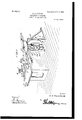
- Figure 1 is a perspective view of a machine embodying the invention.
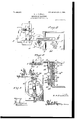
- Fig. 2 is a top plan view.
- Fig. 3 is a sectional view on the line X X of Fig. 2.
- Fig. 4 is a sectional view on the line Y Y of Fig. 2.
- the numeral 1 indicates the rear end portion of a planer, the same being provided with transverse slots 2, through which fastenings 3 pass, said fastenings securing a guideblock 4 to the bed of the planer, as well as a longitudinal guide member 5.
- the guide member 5 projects beyond the end of the planer, as shown in the drawings.
- Extensions 6 project upwardly from the guide-block 4 and the guide member 5 and carry vertically-adjustable plates 7, adapted to bear against the upper side of the material as the latter is fed from the planer between the parts 4 and 5.
- the machine embodying this invention comprises a bed-plate 8, which is rigidly secured to the floor or other base upon which the machine rests, a vertical supporting-plate 9 projecting upwardly from the bed-plate 8.
- the guide member 5 comprises upper and lower plates in spaced relation, and the outer extended end of the guide member is connected with a bracket 10, which is attached to the upper portion of the supporting-plate 9 and adapted for vertical adjustment thereon.
- the bracket 10 is provided with a vertical slot through which a fastening passes, this structure admitting of the vertical adjustment of the bracket for purposes which will appear more fully hereinafter.
- the bracket 10 is mounted upon the outer side of the plate 9, which forms a part of the supporting-frame of the machine comprising this invention, and upon the inner side of said plate 9 is mounted the mandrel-supporting frame 11.
- the frame 11 is preferably of somewhat circular formation, though not necessarily so, and said frame is adapted for special adjustment to thereby vary the position of the mandrel 12, which carries the saw 13.
- Theinner side of the plate 9 is formed with a vertical recess 14, extending almost from the bottom to the top of the plate, and movably mounted in this recess is a vertically-sliding bar 15.
- Fastenings 16 and 16 connect the bar 15 with the plate 9 and pass through vertical slots 17, formed in said plate 9 longitudinally of the recess 14, before described.
- Three of the fastenings are preferably employed, and fastenings 16 not only pass through the openings in the bar 15, but also pass through the mandrel-supporting frame 11, so as to support the latter upon the plate 9.
- the mandrelesupporting frame 11 may be adjusted vertically, so as to raise and lower the saw 13, admitting of cutting the material to a greater or less thickness, as necessary for the purposes of the invention.
- the fastenings 16 pass through arcuate slots 18 in the upper and lower portions of the frame 11, so that said frame is not only ad apted for vertical adjustment by vertical movement of the bar 15, but is also adapted for a certain amount of lateral or pivotal adjustment upon the plate 9 to vary the incli- IIC nation of the saw from the horizontal.
- the intermediate fastening 16 which passes through a slot 17 in the plate 9 and an opening in the bar 15, is integral with the mandrel -supporting frame 11, and when this frame 11 is adjusted so as to vary the inclination of the saw, as above described, being moved independently ofthe bar 15 in such adjusting operation, the intermediate fastening 16 virtually forms a pivotal support for the frame 11 in such movement.
- the mandrel-supporting frame 11 when the mandrel-supporting frame 11 is adjusted vertically said frame is elevated, together with the vertically-movable bar 15; but when it is adjusted pivotally or angularly, so as to incline the saw from the horizontal, said frame 11. is adjusted independently of the bar 15.
- the bar 15 is provided at its lower extremity with an outwardly-projecting extension 19, which is arranged just below the lower end of the frame 11 and which is adapted to engage the frame when the bar 15 is raised.
- An adjustingscrew 20 is adjustable vertically in an interal bracket 21, which projects outwardly rom the plate 9 beneath the extension 19, and by adjusting this screw 20 the upper extremity thereof may be caused to bear against the extension 19 aforesaid, so as to move the bar 15 upwardly or lower said bar.
- the mandrel 12 is mounted in suitable bearing-boxes 22, carried by a bearing-plate 23, said plate 23 being attached to the outer side of the mandrcl-supporting frame 1 1 over the heads of the bolts 16, thereby retaining the said bolts in position as against longitudinal displacement even when the nu ts there of are loosened or detached.
- the mandrel 12 may be adjusted vertically in its bearings and is provided with a pulley 24, by which the motor is connected therewith.
- the saw 13 when in operative position extends through the space between the plates comprising the guide member 5 and is adapted to operate uponthc material fed thereto from the planer as said material leaves the planer, being directed to the saw by means of the members 4 and 5, which have been described before.
- the plate 9 is connected with the bed-plate 8 by a suitable brace 25.
- the mounting of the mandrel-supporting frame is such that the same may be readily adjusted vertically to raise and lower the saw 13 in a horizontal plane, and, further, said frame may be adjusted laterally or angularly, so as to tilt the saw 13 upwardly or downwardly with reference to the material being operated upon, so as to cut the material at an inclination desired by the operator.
- a supporting-base provided with a vertically-extending standard or plate provided at its lower end with a projection 21, and also provided with a plurality of elongated slots, a bar mounted at one side of said plate and provided at its lower end with an outwardlyprojecting extension, an adjusting device or screw working through the projection 21 against the said extension whereby to move the said bar vertically, a mandrel-supporting frame supported at its lower end on the said extension and abutting against the outer face of the said bar and provided with upper and lower curved slots, fastenings or bolts accommodated in said slots and extending through said bar and through the slots in the plate, a pivoted bolt seeurcd to said frame and passing through one of the slots in the plate, a hearing plate 23 attached to the outer side of the mandrel-sum' orting frame and over the heads of the said bolts whereby the latter are retained in position as against longitudinal displacement, and
Landscapes
- Life Sciences & Earth Sciences (AREA)
- Forests & Forestry (AREA)
- Engineering & Computer Science (AREA)
- Mechanical Engineering (AREA)
- Milling, Drilling, And Turning Of Wood (AREA)
Description
PATBNTED JAN. 9, 1906.
L. A. LAWHON. RESAWING MACHINE.
APPLICATION FILED MAY 3, 1905.
PATEN'I'ED JAN. 9, 1906.
L. A. LAWHON. RESAWING MACHINE. APPLICATION FILED MAY a 1905 2 SHEETS-SHEET 2.
' v 7 attog-ncgs PATENT orrron.
LENORD LAWHON, OF MoBEE, SOUTH CAROLINA.
RESAWING-IVIAGHINE.
Specification of Letters Patent.
Patented Jan. 9, 1906.
Application filed May 3, 1905. Serial No, 258,662.
To all whom it may concern:
Be it known that I, LENORD A. LAWI-ION, a cltizen of the United States, residing at McBee, in the county of Chesterfield and State of South Carolina, have invented certain new and useful Improvements in Resawrng-Machines, of which the following is a specification.
This invention provides improvements in wood-working machines, and comprises a novel form of resawing-machine designed especially for use in connection with planers to operate upon the material as it leaves the planer, and thereby obviate the necessity for runnmg the same through an entirely sepa rate machine by an independent operation,
accomplishing a saving of time and labor of.
obvious importance to those versed in the art to which the invention relates.
In its general organization the machine embodying the invention comprises a suitable support upon which is mounted a man' drel-frame adapted for peculiar adjustment, forming an essential feature of the invention, the mandrel carrying the saw, which operates at the rear end of the planer, so that the feed of the latter is advantageously utilized to feed the material to. the resawing-machine, as W1ll appear more fully as the description proceeds.
For a full description of the invention and the merits thereof and also to acquire a knowledge of the details of construction of the means for effecting the result reference is to be had to the following description and accompanying drawings, in which Figure 1 is a perspective view of a machine embodying the invention. Fig. 2 is a top plan view. Fig. 3 is a sectional view on the line X X of Fig. 2. Fig. 4 is a sectional view on the line Y Y of Fig. 2.
Corresponding and like parts are referred to in the following description and indicated in all the views of the drawings by the same reference characters.
Referring to the drawings, the numeral 1 indicates the rear end portion of a planer, the same being provided with transverse slots 2, through which fastenings 3 pass, said fastenings securing a guideblock 4 to the bed of the planer, as well as a longitudinal guide member 5. The guide member 5 projects beyond the end of the planer, as shown in the drawings. Extensions 6 project upwardly from the guide-block 4 and the guide member 5 and carry vertically-adjustable plates 7, adapted to bear against the upper side of the material as the latter is fed from the planer between the parts 4 and 5. The machine embodying this invention comprises a bed-plate 8, which is rigidly secured to the floor or other base upon which the machine rests, a vertical supporting-plate 9 projecting upwardly from the bed-plate 8. The guide member 5 comprises upper and lower plates in spaced relation, and the outer extended end of the guide member is connected with a bracket 10, which is attached to the upper portion of the supporting-plate 9 and adapted for vertical adjustment thereon. The bracket 10 is provided with a vertical slot through which a fastening passes, this structure admitting of the vertical adjustment of the bracket for purposes which will appear more fully hereinafter. The bracket 10 is mounted upon the outer side of the plate 9, which forms a part of the supporting-frame of the machine comprising this invention, and upon the inner side of said plate 9 is mounted the mandrel-supporting frame 11. The frame 11 is preferably of somewhat circular formation, though not necessarily so, and said frame is adapted for special adjustment to thereby vary the position of the mandrel 12, which carries the saw 13. Theinner side of the plate 9 is formed with a vertical recess 14, extending almost from the bottom to the top of the plate, and movably mounted in this recess is a vertically-sliding bar 15. Fastenings 16 and 16 connect the bar 15 with the plate 9 and pass through vertical slots 17, formed in said plate 9 longitudinally of the recess 14, before described. Three of the fastenings are preferably employed, and fastenings 16 not only pass through the openings in the bar 15, but also pass through the mandrel-supporting frame 11, so as to support the latter upon the plate 9.
By the provision of the slots 17 it will be noted that the mandrelesupporting frame 11 may be adjusted vertically, so as to raise and lower the saw 13, admitting of cutting the material to a greater or less thickness, as necessary for the purposes of the invention. The fastenings 16 pass through arcuate slots 18 in the upper and lower portions of the frame 11, so that said frame is not only ad apted for vertical adjustment by vertical movement of the bar 15, but is also adapted for a certain amount of lateral or pivotal adjustment upon the plate 9 to vary the incli- IIC nation of the saw from the horizontal. The intermediate fastening 16, which passes through a slot 17 in the plate 9 and an opening in the bar 15, is integral with the mandrel -supporting frame 11, and when this frame 11 is adjusted so as to vary the inclination of the saw, as above described, being moved independently ofthe bar 15 in such adjusting operation, the intermediate fastening 16 virtually forms a pivotal support for the frame 11 in such movement. In other Words, when the mandrel-supporting frame 11 is adjusted vertically said frame is elevated, together with the vertically-movable bar 15; but when it is adjusted pivotally or angularly, so as to incline the saw from the horizontal, said frame 11. is adjusted independently of the bar 15. The bar 15 is provided at its lower extremity with an outwardly-projecting extension 19, which is arranged just below the lower end of the frame 11 and which is adapted to engage the frame when the bar 15 is raised. An adjustingscrew 20 is adjustable vertically in an interal bracket 21, which projects outwardly rom the plate 9 beneath the extension 19, and by adjusting this screw 20 the upper extremity thereof may be caused to bear against the extension 19 aforesaid, so as to move the bar 15 upwardly or lower said bar.
The mandrel 12 is mounted in suitable bearing-boxes 22, carried by a bearing-plate 23, said plate 23 being attached to the outer side of the mandrcl-supporting frame 1 1 over the heads of the bolts 16, thereby retaining the said bolts in position as against longitudinal displacement even when the nu ts there of are loosened or detached. The mandrel 12 may be adjusted vertically in its bearings and is provided with a pulley 24, by which the motor is connected therewith.
The saw 13 when in operative position extends through the space between the plates comprising the guide member 5 and is adapted to operate uponthc material fed thereto from the planer as said material leaves the planer, being directed to the saw by means of the members 4 and 5, which have been described before. The plate 9 is connected with the bed-plate 8 by a suitable brace 25. The mounting of the mandrel-supporting frame is such that the same may be readily adjusted vertically to raise and lower the saw 13 in a horizontal plane, and, further, said frame may be adjusted laterally or angularly, so as to tilt the saw 13 upwardly or downwardly with reference to the material being operated upon, so as to cut the material at an inclination desired by the operator.
Having thus described the invention, what is claimed as new isln a resawing-machine, the combination of a supporting-base provided with a vertically-extending standard or plate provided at its lower end with a projection 21, and also provided with a plurality of elongated slots, a bar mounted at one side of said plate and provided at its lower end with an outwardlyprojecting extension, an adjusting device or screw working through the projection 21 against the said extension whereby to move the said bar vertically, a mandrel-supporting frame supported at its lower end on the said extension and abutting against the outer face of the said bar and provided with upper and lower curved slots, fastenings or bolts accommodated in said slots and extending through said bar and through the slots in the plate, a pivoted bolt seeurcd to said frame and passing through one of the slots in the plate, a hearing plate 23 attached to the outer side of the mandrel-sum' orting frame and over the heads of the said bolts whereby the latter are retained in position as against longitudinal displacement, and a mandrel or shaft j ournaled in said bearing-plate and carrying a saw at one end, as for the purpose set forth.
In testimony whereof I affix my signature in presence of two witnesses.
LENORD A. LAWHON. l/Vitnesses:
THos. EVERETTE, R. B. McDoNALD.
Priority Applications (1)
| Application Number | Priority Date | Filing Date | Title |
|---|---|---|---|
| US1905258662 US809307A (en) | 1905-05-03 | 1905-05-03 | Resawing-machine. |
Applications Claiming Priority (1)
| Application Number | Priority Date | Filing Date | Title |
|---|---|---|---|
| US1905258662 US809307A (en) | 1905-05-03 | 1905-05-03 | Resawing-machine. |
Publications (1)
| Publication Number | Publication Date |
|---|---|
| US809307A true US809307A (en) | 1906-01-09 |
Family
ID=2877788
Family Applications (1)
| Application Number | Title | Priority Date | Filing Date |
|---|---|---|---|
| US1905258662 Expired - Lifetime US809307A (en) | 1905-05-03 | 1905-05-03 | Resawing-machine. |
Country Status (1)
| Country | Link |
|---|---|
| US (1) | US809307A (en) |
-
1905
- 1905-05-03 US US1905258662 patent/US809307A/en not_active Expired - Lifetime
Similar Documents
| Publication | Publication Date | Title |
|---|---|---|
| US809307A (en) | Resawing-machine. | |
| US141975A (en) | Improvement in sawimg-machines | |
| US328794A (en) | Planing and resawing machine | |
| US354773A (en) | Buzz-planer | |
| US108189A (en) | Improvement in machines for dressing fellies | |
| US210763A (en) | Improvement in universal wood-workers | |
| US487589A (en) | taylor | |
| US131094A (en) | Elijah stoiste gilmoee | |
| US130681A (en) | Improvement in general joiners | |
| US418118A (en) | Joseph w | |
| US142015A (en) | Improvement in machines for raising panels | |
| US623485A (en) | Relishing attachment for tenoni ng-machi n es | |
| US663871A (en) | Scroll-sawing machine. | |
| US726968A (en) | Woodworking-machine. | |
| US715432A (en) | Woodworking-machine. | |
| US413348A (en) | Slate-dressing machine | |
| US570197A (en) | Third to j | |
| US122774A (en) | Improvement in panel-raising machines | |
| US444457A (en) | newman | |
| US221818A (en) | Improvement in mitering attachments for sawing-machines | |
| US216070A (en) | Improvement in blind-slat-planing machines | |
| US204403A (en) | Improvement in machines for planing and sawing wood | |
| US99513A (en) | Improvement in stone-cutting machines | |
| US158291A (en) | Improvement in machines for making fence-pickets | |
| US881107A (en) | Band-saw. |