US809273A - Liquid-measuring device. - Google Patents
Liquid-measuring device. Download PDFInfo
- Publication number
- US809273A US809273A US11528202A US1902115282A US809273A US 809273 A US809273 A US 809273A US 11528202 A US11528202 A US 11528202A US 1902115282 A US1902115282 A US 1902115282A US 809273 A US809273 A US 809273A
- Authority
- US
- United States
- Prior art keywords
- pipe
- reservoir
- vessels
- liquid
- vessel
- Prior art date
- Legal status (The legal status is an assumption and is not a legal conclusion. Google has not performed a legal analysis and makes no representation as to the accuracy of the status listed.)
- Expired - Lifetime
Links
- 239000007788 liquid Substances 0.000 description 6
- 241001251753 Riparia cincta Species 0.000 description 3
- 238000010276 construction Methods 0.000 description 2
- 230000002452 interceptive effect Effects 0.000 description 2
- 230000015572 biosynthetic process Effects 0.000 description 1
- 230000000994 depressogenic effect Effects 0.000 description 1
- 238000007599 discharging Methods 0.000 description 1
- 239000002184 metal Substances 0.000 description 1
- 230000000284 resting effect Effects 0.000 description 1
Images
Classifications
-
- G—PHYSICS
- G01—MEASURING; TESTING
- G01F—MEASURING VOLUME, VOLUME FLOW, MASS FLOW OR LIQUID LEVEL; METERING BY VOLUME
- G01F11/00—Apparatus requiring external operation adapted at each repeated and identical operation to measure and separate a predetermined volume of fluid or fluent solid material from a supply or container, without regard to weight, and to deliver it
- G01F11/28—Apparatus requiring external operation adapted at each repeated and identical operation to measure and separate a predetermined volume of fluid or fluent solid material from a supply or container, without regard to weight, and to deliver it with stationary measuring chambers having constant volume during measurement
- G01F11/36—Apparatus requiring external operation adapted at each repeated and identical operation to measure and separate a predetermined volume of fluid or fluent solid material from a supply or container, without regard to weight, and to deliver it with stationary measuring chambers having constant volume during measurement with supply or discharge valves of the rectilinearly-moved slide type
- G01F11/40—Apparatus requiring external operation adapted at each repeated and identical operation to measure and separate a predetermined volume of fluid or fluent solid material from a supply or container, without regard to weight, and to deliver it with stationary measuring chambers having constant volume during measurement with supply or discharge valves of the rectilinearly-moved slide type for fluent solid material
Definitions
- Our invention relates to improvements in liquid-measuring devices more especially designed for measuring oil and adapted to'rapidly deliver a certain predetermined quantity without requiring accurate attention of the attendant.
- the object of thisinvention is more espezo cially to improve upon the measuring device disclosed in United States Letters Patent N 0. 675,290, granted May 28, 1901.
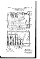
- Figure I is a front side elevation, largely in section, of a measuring device embodying our invention.
- Fig. II is a top plan in horizontal section on line II II
- Fig. I is a right-hand side elevation in section on line III III
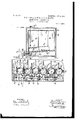
- Fig. IV is a front side elevation in section on line IV IV, Fig. III, of a portion of the device. Fig. IV is drawn on a larger scale than the preceding figures.
- Our improved measuring device is contained 4 in the main within a case or cabinet at and comprises a metal tank or reservoir b for containing the body of oil or liquid (not shown) from which a predetermined quantity is drainable at a time.
- the reservoir 6 is provided at the top with an inlet-forming liquid-receiving aperture [2, which is flanged upwardly and annularly, as at6
- the flange b is screwthreaded externally and embraced by a correspondingly internally threaded cap 0, which 5 closes the said inlet.
- the reservoir 6 is supplied with liquid at the inletb upon the re- .moval of the cap 0, to which access is had through an opening a, formed in the top of the case a, which opening is normally closed by a suitably-applied lid or cover (Z.
- the bottom 6 of the chamber of the reservoir Z) declines forwardly and is depressed next to the front of the said reservoir, so as to form a trough e, which is arranged in a horizontal plane along. the said front and forms a downward enlargement of the said chamber next rearward of the said front.
- a row of closed parallel measuring vessels f arranged a short distance apart laterally.
- the illustrated measuring device has six vessels f.
- Each Vessel f is provided at the top and near the rear end with a vent-pipe g, which extends upwardly into close proximity to the top of the reservoir 6, which is provided in the top thereof with a vent-pipe j, which (see Fig. 1,) projects upwardly through the top of the case a and is provided above the said case with a normally closed valve j.
- a pipe it which extends longitudinally of the said trough below the forward and lower ends of the vessels f.
- the pipe 72 extends a suitable distance beyond the left-hand end of the row of vessels f and is open at its left-hand end and there communicates with the interior of the trough e, and consequently with the chamber of the reservoir 6.
- the pipe it is provided at the top with asmany upwardly-projecting tubular members it as there are vessels f, and one of the said members it forms the right-hand end of the said pipe.
- the different members it are in open relation at their upper end with the chamber of the different vessels f, respectively, and communicate at their lower end with the passage-way formed by and interiorly and longitudinally of the pipe it.
- each vessel f is soldered or otherwise attached to the pipe member it with which the said vessel communicates, and the bottom of the said vessel at the forward end of the vessel and next over the said member it is apertured or perforated, as at f, so as'to establish communication between the said mem- 5 ber h and the chamber of the said vessel.
- the pipe it is provided between adjacent Vessels f with a normally open valve L, adapted to control continuity in the passage-way formed by and within the said pipe, which valve is arranged preferably centrally between the pipe members it', which communicate with the said vessels.
- the pipe it is provided also at the left-hand or outer side of the outermost vessel f at the left-hand end of the row of vessels f with a normally open valve la.
- the valves is and Z/ are provided,respectively, with a stem which extends outside of the reservoir Z) and outside of the case or cabinet at and is provided outside of the said case with a handle 7:; for manipulating the connected valve.
- the pipe it is provided at the lower end of its member it, which connects with the second outermost vessel f at theright-hand end of the row of vessels f, with a forwardly-projecting branch or discharge pipe Z, which extends through the front of the case a and is provided outside of the said case with a downwardly-discharging spout Z and a normally closed valve Z for controlling continuity in the passage-way formed by the said branch.
- the measuring vessels f and the connected pipe 71 are submerged when the reservoir 5 is supplied or iilled with oil; that in filling the said reservoir oil passes into the trough e, thence into the pipe it at the open end of the said pipe, and thence into the vessels f, and that the arrangement of the vent-pipes g entirely within the reservoir Z) reduces the escape of oil-vapor from the reservoir b to a minimum.
- fluid-tight joints are provided wherever necessary; but the formation of such joints is too well understood to require illustration and description in this application.
- the outermost vessel f and the next outermost vessel f at the right-hand end of the row of vessels f are smaller than the remaining vesselsf', and suppose that a drainage of each of the said smaller. vessels will yield a halfgallon and that a drainage of each of the larger vessels will yield one gallon.
- a liquid-measuring device the combination, with a liquid-supply reservoir, of a pipe communicating at one end with the liquidreceiving interior space of the reservoir, and contained within the reservoir, which pipe is provided with a valved discharge branch betwem the ends of the pipe and declines toward its said branch from both ends; a row of measuring vessels contained within the reservoir along the pipe and communicating with the passage-way formed by and interiorly of the said pipe, and the valves arranged to control continuity in the said passage-way, substantially as and for the purpose set forth.
- a liquid-measuring device the combination, with a liquid-supply reservoir, of a pipe arranged within the liquid-receiving interior space at the bottom and forward side of the reservoir and communicating at one end with the said space, which pipe is provided with avalved discharge branch between the ends of the pipe. and declines toward its said branch'from both ends; arow of measuring vessels contained within the reservoir along the aforesaid pipe and having bottoms declining toward the pipe, which vessels oommunicate at the lower end of the said bottoms with the passage-way formed by and interiorly of the said pipe, and the valves arranged to control continuity in the said passage-way, substantially as and for the purpose set forth.
- a liquid-measuring device the combination, with a liquid-supply reservoir of a row of vented measuring vessels within the lower portion of the reservoir, which row is arranged widthwise of the reservoir; a pipe arranged at the bottom and longitudinally of the row of measuring vessels and provided with avalved discharge branch extending outside of the reservoir, which pipe is contained within the liquid-receiving interior space of the reservoir and communicates with the interior chambers of the aforesaid vessels, and normally open valves arranged to control continuity in the passage-way formed by and within the said pipe, substantially as and for the purpose set forth.
- a liquid-measuring device the combination, with a liquid-supply reservoir, of a row of vented measuring vessels contained within the lower portion of the liquid-receiving interior space of the reservoir, which vessels have their bottoms declining toward the front of the reservoir and have outlets at the lower ends of the said bottom; a pipe arranged within the liquid-receiving interior space of the reservoir and extending longitudinally of the aforesaid row of vessels, which pipe is provided with a valved discharge branch extending outside of the said space and communicates with the aforesaid outlets, normally open valves arranged to control continuity in the passage-way formed by and within the said pipe and arranged as required to render any one or more of the aforesaid vessels drainable through the said pipe and the connected branch without moving or interfering with the contents of the remaining vessel or vessels, and
- a liquid-measuring device with a liquid-supply reservoir having a declining bottom and a trough arranged at the lower end of the said bottom and in open relation with the chamber of the reservoir, of a plurality of vented measuring vessels arranged over the said bottom and contained within the chamber of the reservoir, a pipe arranged within and longitudinally of the said trough and provided with a valved discharge branch extending outside of the said trough, which pipe is in open relation withthe chambers of the said vessels, the said normally open valves arranged to control continuity in the passage-ways formed by and within the said pipe, substantially as and for the purpose set forth.
- a liquid-measuring device the combination, with a liquid-supply reservoir having a declining bottom and a trough arranged at the lower end of the said bottom and in open relation with the chamber of the reservoir, of a row of vented measuring vessels arranged over the said bottom and contained within the chamber of the reservoir; a pipe arranged within and longitudinally of the said trough and provided with a valved dischargebranch which extends outside of the said trough and having upwardly-projecting tubular members which connect at their lower ends with the passage-way formed within and extending longitudinally of the said pipe and communicate, at the upper end, with the chamber of the different measuring vessels, respectively, which pipe has one of the said upwardly-projecting members forming one end of the said pipe and is open at its opposite end; normally open valves arranged to control continuity in the aforesaid passage-way between the measuring vessels, and another normally open valve arranged to control continuity in the said passage-way between the open extremity of the pipe and the adjacent side of the adjacent measuring vessel.
Landscapes
- Physics & Mathematics (AREA)
- Fluid Mechanics (AREA)
- General Physics & Mathematics (AREA)
- Loading And Unloading Of Fuel Tanks Or Ships (AREA)
Description
No. 809,273. V PATENTED JAN. 2, 1906. F. S. TURNER, S. PHASE & W. B. MARTIN.
LIQUID MEASURING DEVICE.
APPLIUATION FILED JULY 12, 1902.
2 SHBBTS-SHBET l.
No. 809,273. 7 PATENTED JAN. 2, 1906. F. s. TURNER, s. PEASE & W. B. MARTIN. LIQUID MEASURING DEVICE.
APPLICATION TILED JULY 12,1902.
2 SHEETS-SHEET 2.
WITNESSES IyENAO/ PS BWMLE w g' BY R Ah Q, K
A TTOBNE Ys UNITED STATES PATENT OFFICE.
FRANK S. TURNER, SUMNER PEASE, AND WARD B. MARTIN, OF GENEVA, OHIO, ASSIGNORS, BY MESNE ASSIGNMENTS, TO W. B. MARTIN.
LIQUID-MEASURING DEVICE.
Specification of Letters Patent.
Patented Jan. 2, 1906.
Application filed July 12, 1902- Serial No. 115,282-
To all whom it may concern.-
Be it known that we, FRANK S. TURNER, SUMNER PEAsE, and WARD B. MARTIN, citizens of the United States of America, and residents of Geneva, in the county of Ashtabula and State of Ohio, have invented certain new and useful Improvements in Liquid-Measuring Devices; and we do hereby declare the following to be a full, clear, and exact description of the invention, such as will enable others skilled in the art to which it pertains to make and use the same.
Our invention relates to improvements in liquid-measuring devices more especially designed for measuring oil and adapted to'rapidly deliver a certain predetermined quantity without requiring accurate attention of the attendant.
The object of thisinvention is more espezo cially to improve upon the measuring device disclosed in United States Letters Patent N 0. 675,290, granted May 28, 1901.
With this object in view and to render the device cleanly and convenient and reliable in its operation our invention consists in certain features of construction and combinations of parts hereinafter described, and pointed out in the claims.
In the accompanying drawings, Figure I is a front side elevation, largely in section, of a measuring device embodying our invention. Fig. II is a top plan in horizontal section on line II II, Fig. I. Fig. III is a right-hand side elevation in section on line III III, Fig.
I. Fig. IV is a front side elevation in section on line IV IV, Fig. III, of a portion of the device. Fig. IV is drawn on a larger scale than the preceding figures.
Our improved measuring device is contained 4 in the main within a case or cabinet at and comprises a metal tank or reservoir b for containing the body of oil or liquid (not shown) from which a predetermined quantity is drainable at a time. The reservoir 6 is provided at the top with an inlet-forming liquid-receiving aperture [2, which is flanged upwardly and annularly, as at6 The flange b is screwthreaded externally and embraced by a correspondingly internally threaded cap 0, which 5 closes the said inlet. The reservoir 6 is supplied with liquid at the inletb upon the re- .moval of the cap 0, to which access is had through an opening a, formed in the top of the case a, which opening is normally closed by a suitably-applied lid or cover (Z.
The bottom 6 of the chamber of the reservoir Z) declines forwardly and is depressed next to the front of the said reservoir, so as to form a trough e, which is arranged in a horizontal plane along. the said front and forms a downward enlargement of the said chamber next rearward of the said front. Upon the bottom 6 is a row of closed parallel measuring vessels f, arranged a short distance apart laterally. The vessels f'are preferably 5 metallic and cylindrical, resting upon the aforesaid bottom, and consequently declining forwardly and extend over and transversely of the trough e and preferably abut at their forward ends against the inner side of the 7 front of the reservoir 6. The illustrated measuring device has six vessels f. Each Vessel f is provided at the top and near the rear end with a vent-pipe g, which extends upwardly into close proximity to the top of the reservoir 6, which is provided in the top thereof with a vent-pipe j, which (see Fig. 1,) projects upwardly through the top of the case a and is provided above the said case with a normally closed valve j. Within the trough e is arranged a pipe it, which extends longitudinally of the said trough below the forward and lower ends of the vessels f. The pipe 72. extends a suitable distance beyond the left-hand end of the row of vessels f and is open at its left-hand end and there communicates with the interior of the trough e, and consequently with the chamber of the reservoir 6. The pipe it is provided at the top with asmany upwardly-projecting tubular members it as there are vessels f, and one of the said members it forms the right-hand end of the said pipe. The different members it are in open relation at their upper end with the chamber of the different vessels f, respectively, and communicate at their lower end with the passage-way formed by and interiorly and longitudinally of the pipe it. Preferably each vessel f is soldered or otherwise attached to the pipe member it with which the said vessel communicates, and the bottom of the said vessel at the forward end of the vessel and next over the said member it is apertured or perforated, as at f, so as'to establish communication between the said mem- 5 ber h and the chamber of the said vessel.
IOO
The pipe it is provided between adjacent Vessels f with a normally open valve L, adapted to control continuity in the passage-way formed by and within the said pipe, which valve is arranged preferably centrally between the pipe members it', which communicate with the said vessels. The pipe it is provided also at the left-hand or outer side of the outermost vessel f at the left-hand end of the row of vessels f with a normally open valve la. The valves is and Z/ are provided,respectively, with a stem which extends outside of the reservoir Z) and outside of the case or cabinet at and is provided outside of the said case with a handle 7:; for manipulating the connected valve.
The pipe it is provided at the lower end of its member it, which connects with the second outermost vessel f at theright-hand end of the row of vessels f, with a forwardly-projecting branch or discharge pipe Z, which extends through the front of the case a and is provided outside of the said case with a downwardly-discharging spout Z and a normally closed valve Z for controlling continuity in the passage-way formed by the said branch.
By the construction hereinbefore described it will be observed that the measuring vessels f and the connected pipe 71, are submerged when the reservoir 5 is supplied or iilled with oil; that in filling the said reservoir oil passes into the trough e, thence into the pipe it at the open end of the said pipe, and thence into the vessels f, and that the arrangement of the vent-pipes g entirely within the reservoir Z) reduces the escape of oil-vapor from the reservoir b to a minimum. Of course fluid-tight joints are provided wherever necessary; but the formation of such joints is too well understood to require illustration and description in this application.
The outermost vessel f and the next outermost vessel f at the right-hand end of the row of vessels f are smaller than the remaining vesselsf', and suppose that a drainage of each of the said smaller. vessels will yield a halfgallon and that a drainage of each of the larger vessels will yield one gallon. Obviously then only the inner smaller vessel f or a half-gallon would upon opening the valve Z after closing the valves Z; between the said vessel and the adjacent vessels f be drained through the discharge-pipe l; that upon opening the valve Z after closing only the valve is between the inner smaller vessel f and the next adjacent larger vessel f both smaller vessels f, or one gallon, are drained through the pipe Z, and obviously one and one-half gallons, two gallons, two and one-half gallons, three gallons, three and one-half gallons, four gallons, four and one-half gallons, or five gallons can be drained upon opening the valve Z after closing the required valve or valves 7:, and that the valve 71; at the outer side of the outermost larger vessel f at the left-hand end of the row of vessels f must be closed preparatory to draining the said outermost vessel.
It is obvious that by the pipe it and its members it a passage-way is formed between each measuring vessel f and the discharge-pipe Z; that the location of the said vessels and connected pipe it within the reservoir 5 renders the device cleanly, convenient, and compact; that the trough 6 forms a downward extension of the forward portion of the interior chamber of the oilsupply reservoir, and that the said chamber and its said extension downwardly into the said trough constitutes the liquid-receiving interior space of the said reservoir, and we would have it understood that our invention broadly embraces the combination, with any liquid-supply reservoir, of a row of measuring vessels arranged with the liquid-receiving interior space of the reservoir at suitable intervals widthwise of the reservoir, a discharge-pipe arranged to discharge externally of the reservoir, and the passage-ways formed by the pipe it and its members 7t and valves, whereby one or more of the said vessels can be drained at a time through the said discharge-pipe without moving or interfering with the contents of the remaining vessel or vessels, with the said valves and passage-ways contained within the aforesaid liquid-receiving space of the reservoir, so that any oil or liquid leaking from the said passage-ways and valves does not run onto the floor upon which our improved measuring-cabinetis placed. We would remark also that the arrangement of the measuring vessels in a row widthwise of the reservoir, with the bottoms of the vessels declining toward the front of the cabinet, with the outlets of the said vessels at the lower ends of the said bottoms, and with the pipe it declining from both ends toward the discharge-pipe Z, perfect drainage of any vessel or vessels which are to be drained is insured. It will be observed also that the pipe it declines toward the discharge-pipe Zfrom both ends of the said pipe it, so that oil or liquid is rapidly conducted to the said discharge-pipe.
W hat we claim is 1. In a liquid-measuring device, the combination, with a liquid-supply reservoir, of a pipe communicating at one end with the liquidreceiving interior space of the reservoir, and contained within the reservoir, which pipe is provided with a valved discharge branch betwem the ends of the pipe and declines toward its said branch from both ends; a row of measuring vessels contained within the reservoir along the pipe and communicating with the passage-way formed by and interiorly of the said pipe, and the valves arranged to control continuity in the said passage-way, substantially as and for the purpose set forth.
2. In a liquid-measuring device, the combination, with a liquid-supply reservoir, of a pipe arranged within the liquid-receiving interior space at the bottom and forward side of the reservoir and communicating at one end with the said space, which pipe is provided with avalved discharge branch between the ends of the pipe. and declines toward its said branch'from both ends; arow of measuring vessels contained within the reservoir along the aforesaid pipe and having bottoms declining toward the pipe, which vessels oommunicate at the lower end of the said bottoms with the passage-way formed by and interiorly of the said pipe, and the valves arranged to control continuity in the said passage-way, substantially as and for the purpose set forth.
8. In a liquid-measuring device, the combination, with a liquid-supply reservoir of a row of vented measuring vessels within the lower portion of the reservoir, which row is arranged widthwise of the reservoir; a pipe arranged at the bottom and longitudinally of the row of measuring vessels and provided with avalved discharge branch extending outside of the reservoir, which pipe is contained within the liquid-receiving interior space of the reservoir and communicates with the interior chambers of the aforesaid vessels, and normally open valves arranged to control continuity in the passage-way formed by and within the said pipe, substantially as and for the purpose set forth.
4:. In a liquid-measuring device, the combination, with a liquid-supply reservoir, of a row of vented measuring vessels contained within the lower portion of the liquid-receiving interior space of the reservoir, which vessels have their bottoms declining toward the front of the reservoir and have outlets at the lower ends of the said bottom; a pipe arranged within the liquid-receiving interior space of the reservoir and extending longitudinally of the aforesaid row of vessels, which pipe is provided with a valved discharge branch extending outside of the said space and communicates with the aforesaid outlets, normally open valves arranged to control continuity in the passage-way formed by and within the said pipe and arranged as required to render any one or more of the aforesaid vessels drainable through the said pipe and the connected branch without moving or interfering with the contents of the remaining vessel or vessels, and
means for manipulating the said valves from the exterior of the reservoir.
5. In a liquid-measuring device,.the combination, with a liquid-supply reservoir having a declining bottom and a trough arranged at the lower end of the said bottom and in open relation with the chamber of the reservoir, of a plurality of vented measuring vessels arranged over the said bottom and contained within the chamber of the reservoir, a pipe arranged within and longitudinally of the said trough and provided with a valved discharge branch extending outside of the said trough, which pipe is in open relation withthe chambers of the said vessels, the said normally open valves arranged to control continuity in the passage-ways formed by and within the said pipe, substantially as and for the purpose set forth.
6. In a liquid-measuring device, the combination, with a liquid-supply reservoir having a declining bottom and a trough arranged at the lower end of the said bottom and in open relation with the chamber of the reservoir, of a row of vented measuring vessels arranged over the said bottom and contained within the chamber of the reservoir; a pipe arranged within and longitudinally of the said trough and provided with a valved dischargebranch which extends outside of the said trough and having upwardly-projecting tubular members which connect at their lower ends with the passage-way formed within and extending longitudinally of the said pipe and communicate, at the upper end, with the chamber of the different measuring vessels, respectively, which pipe has one of the said upwardly-projecting members forming one end of the said pipe and is open at its opposite end; normally open valves arranged to control continuity in the aforesaid passage-way between the measuring vessels, and another normally open valve arranged to control continuity in the said passage-way between the open extremity of the pipe and the adjacent side of the adjacent measuring vessel.
Signed by us at Geneva, Ohio, this 24th day of June, 1902.
FRANK S. TURNER. SUMNER PEASE. WARD B. MARTIN.
Witnesses: A. B. MARTIN, N. E. KAY.
Priority Applications (1)
| Application Number | Priority Date | Filing Date | Title |
|---|---|---|---|
| US11528202A US809273A (en) | 1902-07-12 | 1902-07-12 | Liquid-measuring device. |
Applications Claiming Priority (1)
| Application Number | Priority Date | Filing Date | Title |
|---|---|---|---|
| US11528202A US809273A (en) | 1902-07-12 | 1902-07-12 | Liquid-measuring device. |
Publications (1)
| Publication Number | Publication Date |
|---|---|
| US809273A true US809273A (en) | 1906-01-02 |
Family
ID=2877754
Family Applications (1)
| Application Number | Title | Priority Date | Filing Date |
|---|---|---|---|
| US11528202A Expired - Lifetime US809273A (en) | 1902-07-12 | 1902-07-12 | Liquid-measuring device. |
Country Status (1)
| Country | Link |
|---|---|
| US (1) | US809273A (en) |
-
1902
- 1902-07-12 US US11528202A patent/US809273A/en not_active Expired - Lifetime
Similar Documents
| Publication | Publication Date | Title |
|---|---|---|
| US809273A (en) | Liquid-measuring device. | |
| US1737929A (en) | Liquid delivery and pumping apparatus | |
| US1509360A (en) | Dispensing can | |
| US306168A (en) | Compound faucet | |
| US650056A (en) | Apparatus for measuring oil. | |
| US543169A (en) | Self-measuring liquid-tank | |
| US484889A (en) | Soda-water apparatus | |
| US687395A (en) | Measuring-faucet. | |
| US677751A (en) | Soda-water fountain. | |
| US1444246A (en) | Crude-oil tank | |
| US897170A (en) | Soda-water fountain. | |
| US248956A (en) | Self-measuring oil-can | |
| DE102009053670C5 (en) | Liquid dispenser | |
| US1603698A (en) | Tank | |
| US145725A (en) | Improvement in combined tanks and liquid-measures | |
| US275419A (en) | Walteb scott | |
| US650309A (en) | Machine for filling bottles. | |
| US1471737A (en) | Automatic water drain for oil tanks | |
| US245528A (en) | marchand | |
| US586855A (en) | Self-measuring storage-tank | |
| US664349A (en) | Automatic measuring device. | |
| US617566A (en) | Apparatus for filling oil-cans | |
| US675290A (en) | Measuring device for liquids. | |
| US1052748A (en) | Device for filling bottles or other receptacles with liquids. | |
| US1475887A (en) | Dispensing apparatus |