US809255A - Car-coupling. - Google Patents
Car-coupling. Download PDFInfo
- Publication number
- US809255A US809255A US28230305A US1905282303A US809255A US 809255 A US809255 A US 809255A US 28230305 A US28230305 A US 28230305A US 1905282303 A US1905282303 A US 1905282303A US 809255 A US809255 A US 809255A
- Authority
- US
- United States
- Prior art keywords
- coupling
- section
- head
- draw
- sections
- Prior art date
- Legal status (The legal status is an assumption and is not a legal conclusion. Google has not performed a legal analysis and makes no representation as to the accuracy of the status listed.)
- Expired - Lifetime
Links
Images
Classifications
-
- B—PERFORMING OPERATIONS; TRANSPORTING
- B61—RAILWAYS
- B61G—COUPLINGS; DRAUGHT AND BUFFING APPLIANCES
- B61G7/00—Details or accessories
- B61G7/14—Safety devices
Definitions
- My invention relates to an improvement in car-couplings, and more particularly to means for coupling or connecting two drawheads of automatic bar-couplings to enable the cars to which the couplings are applied to run on very sharp or short curves, one object of the invention being to provide coupling devices of the described character by means of which the draw-heads on two cars can be connected together in such manner as to enable them to be run on a short curve without liability of the end sills of the respective cars abutting against each other.
- a further object is to provide simple and eflicient devices adapted to be removably attached to a draw-head of an automatic coupling for connecting the coupling-heads of two cars, so as to enable the latter to be run on sharp or short curves, such as are usually found in depot-yards.
- a further object is to provide means adapted to be quickly applied to the cars while the latter are standing on sharp curves.
- a furtherobject is to provide an auxiliary coupling device comprising two coupling sections or heads pivotally connected together, one of said sections having a shouldered rear portion which is adapted to proj ect sufliciently within the horizontal slot of a draw-head of the Janney type of coupler to hold said coupling-sect1on in position and prevent the same from dropping away from the draw-head.
- a further object is to provide an auxiliary coupling device which shall be so constructed and arranged that an eiiective coupling of the two draw-heads of adjacent cars can be eiiected, even though there may be a difference of several inches-i. e. about the height or thickness of the usual coupling-head-be tween the heights of the two draw-heads.
- a further object is to provide an auxiliary coupling device which may be used in connection with an ordinary draft-chain, such as are often used when it is impossible to couple two cars on a sharp curve or to replace a car upon the rails.
- a further object is to provide a coupling device which shall be entirely automatic in its operation and with-which it is unnecessary for the person to remain between the cars during the coupling operation.
- a further object is to provide a coupling device which may be used with the wellknown Janney type of coupling having a slotted knuckle.
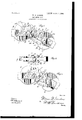
- Figure 1 is a plan view showing the application of my invention for connecting two automatic couplings.
- Fig. 2 is an edge view of Fig. 1.
- Fig. 3 is a view similar to Fig. 1, showing a slightly-modified construction of my coupling device.
- 1 and 2 represent the draw-heads of two automatic couplings of that type wherein a swinging coupling-head of the well-known Janney type is employed. These heads 1 and 2 are to be carried by two adjacent cars, as usual.
- My improved coupling device comprises, essentially, two sections or heads having a pivotal connection with each other, which pivotal connection may be varied, as hereinafter fully explained, one of said sections or heads being constructed to be removably attached to one coupling-head or knuckle carried by one draw-head, while the other section or head is adapted to be engaged by the coupling-head or knuckle carried by the other draw-head.
- the section 3 and 4 indicate the two sections, blocks, or heads of my coupling device.
- the section 3 is made with the contour in plan, (seen in Fig. 1,) it having a cavity or recess 5 corresponding in its contour approximately with the contour of the hook 6 on the swinging knuckle 7, carried by one draw-head, as 1.
- the section 3 also has a shoulder 9 at its rear end, which is adapted to project sufliciently within the horizontal slot of a draw-head to hold said section in position and prevent the same from dropping away from the said draw-head.
- the section 3 is slotted, as seen at 10 in Fig.
- the section 4 is shown as somewhat thickened at 36, so that the said section can be used to couple to a slotted knuckle, the thickening of the section, as stated, preventing the same from passing through the slot of the knuckle, and thereby fail to effect a coupling.
- the section 4 in its contour in plan is practically the same as section 3, excepting that no rear shouldered portion 9 is provided.
- the section 4 is provided with a hook portion 15 and the recess 16 shaped to respectively correspond approximately to the recess 17 and hook 18 of the knuckle carried by the other draw-head 2.
- the hook 18 is adapted to engage within the recess 16, while the hook 15 engages within the recess 17 when the parts are in coupled position.
- the section 4 may be slotted at 21 and apertured at 22 to lighten it, though this may be dispensed with, if desired.
- the section 3 is provided with a bearing edge 24, adapted to abut against the edge 25 of the draw-head to give a firm bearing between the parts when the cars come together, while the section 4 is provided with a bearing edge 26, adapted to bear against the hook 6 when said section 4 is in the position it would have to assume when coupling on an extremely-sharp curve, and section 4 also has a bearing edge 27, adapted to bear against an edge 27 of the draw-head 2.
- a pivotal connection is to be provided between the sections or heads 3 and 4, and in Fig. 1 I show this connection as consisting of two links 28 and 29, one arranged upon the upper side and the other upon the lower side of the sections, and headed bolts 30 and 31 the former passing through apertures in one end of the links and in the portions 11 and 12 and the section 3, while the bolt 31 passes through apertures in the opposite end of the links and section 4.
- the lower ends of the bolts carry threaded tightening nuts 32, which latter when screwed up tightly cause the portions 11 and 120i section 3 to more or less firmly clamp the edge of the section 4 where it enters the slot 10, and thus cause the section 4 to be held from swinging too freely and causing it to remain in adjusted position when set by hand for coupling.
- the slot in the section 4 may serve as a handhold for setting it for coupling.
- Fig. 3 I show a slightly-different construction, wherein the pivotal connection for the sections 3 and 4 differs from that seen in Figs. 1 and 2.
- the links and one of the bolts are dispensed with, and the pivotal connection employed is simply the headed bolt 35, which passes through the sections 3 and 4 and which bolt, like the bolts 30 and 31, may carry a tightening-nut at its lower end.
- the section 3 maybe slightly extended superficially, so as to provide a projection 37 to give additional strength, and the bolt 35 passes down through the superficially-extended portion.
- the section 4 might be dispensed with and the section 3 used to connect with one knuckle of a car and a chain used for attaching at one end to the draw-head or knuckle of the other car, the other end of said chain being secured to section 3 by passing it through the slot 13 and securing it in any desired manner.
- a connecting device for car-couplings comprisin two coupling sections or heads, each of W 11011 is provided with a couplinghook adapted to engage with the respective coupling-knuckles of adjacent cars, and one of said coupling-sections being provided with a shouldered portion at its rear end adapted to project within the slot of a draw-head to hold said couplin -section in position and prevent the same om dropping away from the draw-head, and a pivotal connection between the coupling-sections.
- a connecting device for car-couplings comprisin two coupling sections or heads,
- each of which is provided with a couplinghook adapted to engage with the respective coupling-knuckles of adjacent cars, and a pivot-bolt passing through alined apertures in the coupling-sections.
- a connecting device for car-couplings comprising two coupling sections or heads,
- one section being horizontally I 5 slotted to partially receive the other section in the swinging movements of the latter, and a pivot-bolt passing through alined apertures in the said sections.
Landscapes
- Engineering & Computer Science (AREA)
- Mechanical Engineering (AREA)
- Toys (AREA)
Description
No. 809,255. PATENTED JAN. 2, 1906.
' W. W. GORDON.
CAR COUPLING.
APPLIGATION FILED OCT. 11,1905.
1! 7 A /6 y u I k /f W m fllmllmlllllmml. a, I 11m K H! H dun" MIMI w w mmmnlllll UNITED STATES PATENT OFFICE.
CAP-COUPLING- Specification of Letters Patent.
Patented Jan. 2, 1906.
Application filed October 11, 1905. Serial No. 282,303.
To aZZ whom it may concern:
Be it known that I, WILLIAM W. GORDON, a citizen of the United States, residing at Washington, in the District of Columbia, have invented certain new and useful Improvements in Oar-Couplings, of which the following is a specification.
My invention relates to an improvement in car-couplings, and more particularly to means for coupling or connecting two drawheads of automatic bar-couplings to enable the cars to which the couplings are applied to run on very sharp or short curves, one object of the invention being to provide coupling devices of the described character by means of which the draw-heads on two cars can be connected together in such manner as to enable them to be run on a short curve without liability of the end sills of the respective cars abutting against each other.
A further object is to provide simple and eflicient devices adapted to be removably attached to a draw-head of an automatic coupling for connecting the coupling-heads of two cars, so as to enable the latter to be run on sharp or short curves, such as are usually found in depot-yards.
A further object is to provide means adapted to be quickly applied to the cars while the latter are standing on sharp curves.
A furtherobject is to provide an auxiliary coupling device comprising two coupling sections or heads pivotally connected together, one of said sections having a shouldered rear portion which is adapted to proj ect sufliciently within the horizontal slot of a draw-head of the Janney type of coupler to hold said coupling-sect1on in position and prevent the same from dropping away from the draw-head. I
A further object is to provide an auxiliary coupling device which shall be so constructed and arranged that an eiiective coupling of the two draw-heads of adjacent cars can be eiiected, even though there may be a difference of several inches-i. e. about the height or thickness of the usual coupling-head-be tween the heights of the two draw-heads.
A further object is to provide an auxiliary coupling device which may be used in connection with an ordinary draft-chain, such as are often used when it is impossible to couple two cars on a sharp curve or to replace a car upon the rails.
A further object is to provide a coupling device which shall be entirely automatic in its operation and with-which it is unnecessary for the person to remain between the cars during the coupling operation.
A further object is to provide a coupling device which may be used with the wellknown Janney type of coupling having a slotted knuckle.
With the above and other objects in view the invention consists in the novel construction, arrangement, and combination of parts, as hereinafter fully described, illustrated in the accompanying drawings, and pointed out in the appended claims.
In the drawings, Figure 1 is a plan view showing the application of my invention for connecting two automatic couplings. Fig. 2 is an edge view of Fig. 1. Fig. 3 is a view similar to Fig. 1, showing a slightly-modified construction of my coupling device.
In the drawings, 1 and 2 represent the draw-heads of two automatic couplings of that type wherein a swinging coupling-head of the well-known Janney type is employed. These heads 1 and 2 are to be carried by two adjacent cars, as usual.
My improved coupling device comprises, essentially, two sections or heads having a pivotal connection with each other, which pivotal connection may be varied, as hereinafter fully explained, one of said sections or heads being constructed to be removably attached to one coupling-head or knuckle carried by one draw-head, while the other section or head is adapted to be engaged by the coupling-head or knuckle carried by the other draw-head.
3 and 4 indicate the two sections, blocks, or heads of my coupling device. The section 3 is made with the contour in plan, (seen in Fig. 1,) it having a cavity or recess 5 corresponding in its contour approximately with the contour of the hook 6 on the swinging knuckle 7, carried by one draw-head, as 1. The section 3 also has a shoulder 9 at its rear end, which is adapted to project sufliciently within the horizontal slot of a draw-head to hold said section in position and prevent the same from dropping away from the said draw-head. The section 3 is slotted, as seen at 10 in Fig. 2, so as to permit the section 4 to slightly enter and swing within the slot when being adjusted by handy to different angles according to the character of the curve of the track upon which it is des1red to efl'ect a coupling. By slotting the section 3, as stated, it divides the latter into upper and lower portions 11 and 12 but it will be understood that I do not wish to be restricted to the slotting of the section 3 for practically its entire length, as shown, since the same may be made solid from its tail end more or less toward its front end, leaving a slot just su'lficient to accommodate the swinging movement of the section 4. I, however, show the section 3 as being slotted for nearly its entire length horizontally and also as being slotted, as at 13, and apertured at 14 to somewhat lighten the device, though the slot 13 and aperture 14 need not be provided, if deemed unnecessary.
The section 4 is shown as somewhat thickened at 36, so that the said section can be used to couple to a slotted knuckle, the thickening of the section, as stated, preventing the same from passing through the slot of the knuckle, and thereby fail to effect a coupling.
The section 4 in its contour in plan is practically the same as section 3, excepting that no rear shouldered portion 9 is provided. The section 4 is provided with a hook portion 15 and the recess 16 shaped to respectively correspond approximately to the recess 17 and hook 18 of the knuckle carried by the other draw-head 2. The hook 18 is adapted to engage within the recess 16, while the hook 15 engages within the recess 17 when the parts are in coupled position. When coupling on a curve, the section 4 is first set by hand approximately at the angle desired, and as the cars come together the hook 15 will strike against the tail portion of the knuckle. carried by the draw-head 2 and swing said knuckle so that its hook will engage in the recess 16-behind the hook 15, thus coupling the cars. The section 4 may be slotted at 21 and apertured at 22 to lighten it, though this may be dispensed with, if desired.
The section 3 is provided with a bearing edge 24, adapted to abut against the edge 25 of the draw-head to give a firm bearing between the parts when the cars come together, while the section 4 is provided with a bearing edge 26, adapted to bear against the hook 6 when said section 4 is in the position it would have to assume when coupling on an extremely-sharp curve, and section 4 also has a bearing edge 27, adapted to bear against an edge 27 of the draw-head 2.
In constructing my device a pivotal connection is to be provided between the sections or heads 3 and 4, and in Fig. 1 I show this connection as consisting of two links 28 and 29, one arranged upon the upper side and the other upon the lower side of the sections, and headed bolts 30 and 31 the former passing through apertures in one end of the links and in the portions 11 and 12 and the section 3, while the bolt 31 passes through apertures in the opposite end of the links and section 4. The lower ends of the bolts carry threaded tightening nuts 32, which latter when screwed up tightly cause the portions 11 and 120i section 3 to more or less firmly clamp the edge of the section 4 where it enters the slot 10, and thus cause the section 4 to be held from swinging too freely and causing it to remain in adjusted position when set by hand for coupling.
The slot in the section 4 may serve as a handhold for setting it for coupling.
In Fig. 3 I show a slightly-different construction, wherein the pivotal connection for the sections 3 and 4 differs from that seen in Figs. 1 and 2. In Fig. 3 the links and one of the bolts are dispensed with, and the pivotal connection employed is simply the headed bolt 35, which passes through the sections 3 and 4 and which bolt, like the bolts 30 and 31, may carry a tightening-nut at its lower end. The section 3 maybe slightly extended superficially, so as to provide a projection 37 to give additional strength, and the bolt 35 passes down through the superficially-extended portion.
If desired, the section 4 might be dispensed with and the section 3 used to connect with one knuckle of a car and a chain used for attaching at one end to the draw-head or knuckle of the other car, the other end of said chain being secured to section 3 by passing it through the slot 13 and securing it in any desired manner.
With my device it will be found unnecessary to remove the same when the cars have been run again upon a straight line of track, which removal has been necessary with coupling devices of a similar character as heretofore constructed. It will also be found that by the use of my device no damage can result to the air-brake and steam-heatin pipes of the cars by preventing the usua couplings from lapping.
What I claim, and desire to secure by Letters Patent, is+
1. A connecting device for car-couplings comprisin two coupling sections or heads, each of W 11011 is provided with a couplinghook adapted to engage with the respective coupling-knuckles of adjacent cars, and one of said coupling-sections being provided with a shouldered portion at its rear end adapted to project within the slot of a draw-head to hold said couplin -section in position and prevent the same om dropping away from the draw-head, and a pivotal connection between the coupling-sections.
2. A connecting device for car-couplings comprisin two coupling sections or heads,
each of which is provided with a couplinghook adapted to engage with the respective coupling-knuckles of adjacent cars, and a pivot-bolt passing through alined apertures in the coupling-sections.
A connecting device for car-couplings comprising two coupling sections or heads,
ed to engage with the respective knuckles of adjacent cars, one section being horizontally I 5 slotted to partially receive the other section in the swinging movements of the latter, and a pivot-bolt passing through alined apertures in the said sections.
In testimony whereof I afiix my signature 20 in presence of two witnesses.
WILLIAM W. GORDON.
Witnesses:
CHAS. E. RIORDON, WM. E. BOULTER.
Priority Applications (1)
| Application Number | Priority Date | Filing Date | Title |
|---|---|---|---|
| US28230305A US809255A (en) | 1905-10-11 | 1905-10-11 | Car-coupling. |
Applications Claiming Priority (1)
| Application Number | Priority Date | Filing Date | Title |
|---|---|---|---|
| US28230305A US809255A (en) | 1905-10-11 | 1905-10-11 | Car-coupling. |
Publications (1)
| Publication Number | Publication Date |
|---|---|
| US809255A true US809255A (en) | 1906-01-02 |
Family
ID=2877736
Family Applications (1)
| Application Number | Title | Priority Date | Filing Date |
|---|---|---|---|
| US28230305A Expired - Lifetime US809255A (en) | 1905-10-11 | 1905-10-11 | Car-coupling. |
Country Status (1)
| Country | Link |
|---|---|
| US (1) | US809255A (en) |
-
1905
- 1905-10-11 US US28230305A patent/US809255A/en not_active Expired - Lifetime
Similar Documents
| Publication | Publication Date | Title |
|---|---|---|
| US809255A (en) | Car-coupling. | |
| US581072A (en) | Car-coupling | |
| US700262A (en) | Car-coupling. | |
| US415194A (en) | Car-coupling | |
| US356506A (en) | Marshal miles sanford | |
| US473346A (en) | robinson | |
| US269358A (en) | Car-coupling | |
| US590111A (en) | murphy | |
| US1077240A (en) | Car-coupling device. | |
| US544492A (en) | Car-coupling | |
| US689644A (en) | Car-coupling. | |
| US458528A (en) | green | |
| US474909A (en) | Car-coupling | |
| US703256A (en) | Attachment for car-couplings. | |
| US494246A (en) | Philip c | |
| US298690A (en) | Car-coupling link | |
| US943116A (en) | Automatic car-coupling. | |
| US445245A (en) | flohr | |
| US915341A (en) | Car-coupling device. | |
| US839771A (en) | Emergency-knuckle for car-couplings. | |
| US558061A (en) | Car-coupling | |
| US781486A (en) | Car-coupling. | |
| US190775A (en) | Improvement in car-couplings | |
| US577988A (en) | Car-coupling | |
| USRE10623E (en) | Car-couplinq |