US809242A - Pile-driver. - Google Patents
Pile-driver. Download PDFInfo
- Publication number
- US809242A US809242A US29020204A US1904290202A US809242A US 809242 A US809242 A US 809242A US 29020204 A US29020204 A US 29020204A US 1904290202 A US1904290202 A US 1904290202A US 809242 A US809242 A US 809242A
- Authority
- US
- United States
- Prior art keywords
- shaft
- platform
- truck
- wheel
- gear
- Prior art date
- Legal status (The legal status is an assumption and is not a legal conclusion. Google has not performed a legal analysis and makes no representation as to the accuracy of the status listed.)
- Expired - Lifetime
Links
- 238000010276 construction Methods 0.000 description 4
- 230000002441 reversible effect Effects 0.000 description 4
- 241000212384 Bifora Species 0.000 description 3
- XLYOFNOQVPJJNP-UHFFFAOYSA-N water Substances O XLYOFNOQVPJJNP-UHFFFAOYSA-N 0.000 description 2
- 101100328887 Caenorhabditis elegans col-34 gene Proteins 0.000 description 1
- 150000002500 ions Chemical class 0.000 description 1
- 238000012986 modification Methods 0.000 description 1
- 230000004048 modification Effects 0.000 description 1
Images
Classifications
-
- E—FIXED CONSTRUCTIONS
- E21—EARTH OR ROCK DRILLING; MINING
- E21B—EARTH OR ROCK DRILLING; OBTAINING OIL, GAS, WATER, SOLUBLE OR MELTABLE MATERIALS OR A SLURRY OF MINERALS FROM WELLS
- E21B7/00—Special methods or apparatus for drilling
- E21B7/02—Drilling rigs characterised by means for land transport with their own drive, e.g. skid mounting or wheel mounting
Definitions
- My invention relates to pile-drivers, and has for its object to provide a cheap and simple device of this character whereby the same can be used as a pile-driver, derrick, or traveling crane, as well as one in which wire rope can be used in connection with the ram; and a further obj ect is to provide such a device which will allow the trucks to be lifted from the track and be turned at right angles thereto.
- a still further object of the device is to have such an operation ofthe parts which will relieve the strain on the rope used when the ram is striking, and one 1n which the feeding parts will not turn back when power is taken off, thereby dispensing with the use of braking means.
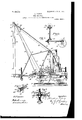
- FIG. 1 is a side elevation of my improved pile-driver.
- Fig. 2 is a top plan view of the pile-driver with the supporting-beams broken away or removed.
- Fig. 3 is a bottom plan view with the track and other parts removed.
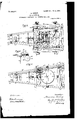
- Fig. 4 is an enlarged detail view showing one of the jacking devices and connections to the samefor operating.
- Fig. 5 is an enlarged detail view of the apparatus forming the truck.
- Fig. 6 is an enlarged detail view of a portion of the jack-operating mechanism.
- Fig. 7 is an enlarged detail view of the spring-actuated sleeve.
- 1 represents the truck-body, which is supported on the axles 2, and on these axles are mounted the wheels 3 for traveling lon the rails 4 of a suitable track.
- On the bed 5 ofthe truck 1 is mounted a circular track 5, on which the wheels or rollers 6 are adapted to travel, and these rollers 6 are mounted and carried bya rotatable platform 7, which is mounted above said truck 1 and is supported by and is rotatable on said track 5 through the medium of said rollers 6.
- a shaft 8 (shown in dotted lines, Fig. 1) passes through said platform 7, and on its upper end is provided the bevelpinion 9, while its lower end is provided with the bevel-pinion 10, which is adapted to mesh with a bevel-pinion 11, mounted on a shaft 12, extending across said axles 2, and
- this shaft 12 is provided with the worms 13 at each end thereof for engaging with a worm-gear 14, mounted on each of said axles.
- the bevel-pinion 9 is adapted to mesh with a bevel-pinion 15, mounted on a shaft 16, which shaft extends across said platform 7 in a parallel line with the rope-drums hereinafter described, and is j ournaled in the bearings 7, carried by said platform.
- a gear-wheel 17 is mounted on said shaft 16, which is adapted to mesh with a gear-wheel 18, mounted on the drum-shaft 19, Awhich carries the drum 20, and this gear-wheel 18 meshes with another gear-wheel 21, mounted on the drum-shaft 22, carrying a drum 23.
- drums 20 and 23 are connected to the engine 24 in the usual manner through the drive-shaft 24', such engine being operated through the boiler 24 and all these parts being mounted on the platform 7, while the shafts 19 and 22 for said drums are j ournaled in the frames or bearing-plates 25, and such frames have also journaled therein the shaft 26, carrying the reversible swinging gear device 27.
- rlhe reversible swinging gear device 27 is of a well-known construction and is controlled by the lever 28, while being operated through a gear-wheel 29, which is mounted on the shaft 26 and meshes with the gear-wheel 21 on the drum-shaft 22.
- a gear-wheel 30 is mounted on a cross-shaft 31, located under the platform 7, and this gear-wheel 30 meshes with the gear-wheel 30 on the shaft 26.
- rIhe shaft 31 is provided with a worm 32- thereon, and such worm is adapted to be engaged, through the clutchface 33, by a clutch 34 on said shaft, which is operated by a lever 35, while said worm 32 is adapted to mesh with a circular worm-rack 36, supported by the standards 37, extending up from the truck-body 1.
- the supporting-beams 38 for carrying the uprights 39 extend under the platform 7 IOC lgear-wheel 52 and form part of the same, while within Y these uprights the ram 40 slides within guides 40 by means of the lugs or flanges 40 thereon.
- These beams carry the rollers 6 for the rotatable platform 7 and the bearings 31 for the shaft 31, ⁇ and such uprights 39 are mounted on a detachable portion 38 of said beams 38, which is connected by bolts 38"l to the permanent portion 38 of said beams.
- each of the screw-bars 43 is mounted on each of the screw-bars 43, and such wheel for-the ⁇ jack 42 is adapted to engage with a worm46,mounted on a cross-shaft 47 supported in bearings 47 extending out from the cross-piece 41.
- pinion 48 is mounted on the end of this shaft 47, which meshes with a like pinion 49 and shaft 50, extending along one of the detachable beam portions 38 and supported in bearings 51, extending out therefrom.
- a gearwheel 52 is mounted on this shaft 50 and is provided with a clutch face 524 thereon, which is adapted to be engaged by a clutch 53 on said shaft 50 and operated by the lever 53 while such gear-wheel 52 meshes with a on a shaft 50', extending along and supported by bearings 51 from the permanent beam portion 38.
- a pinion 51 is mounted on said shaft 50 which meshes with a like pinion 52a, mounted on the crossshaft 31 under the platform 7, and another pinion 53 is mounted on said shaft 50', which is adapted to mesh with a pinion 53a, mounted on a cross-shaft 54, which extends along the cross-piece 41 in suitable bearings and provided with a worm 54 which engages with the worm-wheel 45 on the jack 42, while a worm 55 on said shaft 50 meshes with the worm-wheel 45 on the jack 42.
- a clutch 56 is mounted on the shaft 50 and is adapted to engage with clutch-faces 55 and 55 on said pinion 53 and worm 55, respectively, which clutch 56 is operated by the lever 56.
- the rope 60 which is preferably' formed of wire, is connected at one end of the top of the ra-m 40 and asses over a. shcave 61, mounted on a shaft 61 and journaled in bearings 61 at the top of said uprights 39, while such rope also passes around a spring-operated sheave 62 on the detachable portion 38 of the supporting-beams 38l and is connected at its opposite end to and is wound around the drum 23.
- This spring-operated sheave 62 has its bearings 62 mounted on the end of a rod 62, which extends through a frame 63, easily journaled around a cross-bar 63, extending across and between the detachable beam portions 38 by a sleeve 63, while a spiral spring 64 fits around said rod 62" and is confined between a collar or flange 64 on the end of said rod and a plate 64 on the end of said frame 63.
- a boom 65 is pivoted at -65 in bearings 65" on the permanent portions 38 of said supporting-beams 38 and extends up at an angle or incline to and is connected around the shaft 61 at the upper end of the uprights 39, such boom acting as the ordinary ladder for the uprights 39 of the driver and being supported by the rods 66, which are connected to said boom at 66 and to the upper end of said posts 57 and-cross-piece 41, as at 66.
- the device used in operating the boom 65 is shown by dotted lines in Fig. 1, and consists of rope 67, which passes from the drum 2O over and around a sheave 67,
- the use and operation of my improved pile-driver are as follows:
- the truck 1, carrying the platform 7, is adapted to move along the rails 4 through the medium of the engine 24, operating the gear-wheels 18 and 21 on the drumshafts 19 vand 22, respectively, from the drive-shaft 2 4 inthe usual manner, which, through the gear-wheel 30 on the reversible gear-shaft 26 being engaged by said gear-wheel 21, will act to operate said shaft 26 and revolve the gear-wheel 29 on said shaft, sothat such gear-wheel 29, meshing with the gear-wheel 3,0 on the shaft 31, will act to operate said shaft 31.
- the said wheel 45 will be turned, and with itl the screw-bar 43 of the jack 42, so that said jack will be lowered down to allow its head 44 to come against the ground or block, and such lowering being continued sufficiently will act to raise the outer end of the supporting-beams 38 and one end of the truck 1 from the rails 4.
- the clutch 53 can now be thrown out of engagement with the face 52 on the gear-wheel 52 and the clutch 56 thrown into engagement with the face 55" on the worin 55 through the lever 56', which will cause said worm to turn the worin-wheel 45 on the jack 42', with which it engages, as Vwell as the screw-bar 43 on said jack 42', thereby lowering said jack 42 down onto the ground or block.
- the detachable beam portions 38 can be separated from the permanent portion 38 of the supporting-beams 38 by unscrewing the bolts 38a, connecting these parts together, and then detaching the uprights 39 from the bearings 61, as well as the rods 59 from said uprights and from said posts 57 and the rods 66 from said posts, boom 65, and portions 38, so that said portions 38, uprights 39, rods 59 and 66 can be removed from the device.
- the ram 40 and spring-operated sheave 62 can also be removed, and the rope 60 around the sheave 61 and drum 23 can be attached to a bucket, scraper, &c., which will allow the boom 65 to move freely upon its pivotal point in bearings 65', so that such boom can be raised and lowered on such pivoted bearing from the drum 20 by the engine 24 through the medium of the rope 67, leading from said drum and passing around the sheaves 67 on the posts 57 and the sheaves 68, suspended from the shaft 61 on the outer end of said boom and carrying the sheaves 61 for use in the operation of devices in connection with said boom.
- the pendulum leads on what are known as monkey-drivers can be attached at the top of the boom in .place of the uprights, so that the device can be used for the placing and driving of piles at an angle in the building of railroad and other like trestle-work.
- the I-beams or channelbeams can be used in place of the rails for the wheels of the truck, in which case such wheels can be moved along on the side of said beams and between the flanges therein, so as to allow the wheels to play between such flanges and have the truck in place when the device is rocked or swayed on account of waves, rough water, &c.
- the spring-operated sheave for the wire rope can be placed at other points on the device to operate in connection with said rope, and by its use the strain will be so relieved as to prevent its breaking, as has been found with its use in this class of work. It will further be obvious that by reason of the detachable frame portion the device can be made portable, so that the jacks can be used to raise the platform and trucks, in order that wheels for moving the device from place to place by the engine can be placed upon the axles of said trucks.
- a device of the type described comprising a truck, a rotatable platform mounted thereon, and carrying drums drivinggearing on said platform, for operating said drums an engine on said platform and connected to said gearing for driving the same, a shaft extending under and parallel with said drums and having a gear-wheel thereon for engaging with the driving-gearing, and connections from said shaft to the axles of the truck for moving said truck.
- a device of the type described comprising a truck, a rotatable platform mounted thereon, and carrying drums driving-gearing on said platform, for operating said drums an engine on said platform and connected to said gearing for driving the same, a shaft extending under and parallel with said drums and having a gear-wheel thereon for engaging with the driving-gearing, an upright shaft having a beveled pinion thereon engaging with the beveled pinion on the first-named shaft, and connections fromv said upright shaft to the axles of the truck for moving said truck.
- a device of the type described comprising a truck, va rotatable platform mounted thereon, and carrying drums driving-gearing on said platform, for operating said drums an engine on said platform and connected to said gearing for driving the same, a shaft extending under and parallel with said drums and having a gear-wheel thereon for engagll f ing with the driving-gearing, a beveled pit ion on said shaft, an upright shaft between said truck and platform having beveled pimions at each end thereof and the upper one of said pinions engaging with the-beveled pinion on the first-named shaft, and connections from the lower one of said beveled pin-ions to the axles of the truck for moving said truck.
- a device of the type described comprising a truck, a rotatable platform mounted thereon, and carrying drums driving-gearing on said platform, for operating said drums an engine on said platform and connected to said gearing for driving the same, a shaft extending under and parallel with said drums and having a gear-wheel thereon for engaging with the driving-gearing, a beveled pinion on said shaft, an upright shaft between said truck and platform having bevel-pinions at each end thereof and the upper one of said pinions engaging with the beveled pinion on the first-named shaft, a shaft below said upright shaft having a beveled pinion thereon engaging with the beveled pinion on the lower end of the upright shaft7 and gearing connecting said last-named shaft with the axles of the truck for moving said truck.
- a device of the type described comprising a truck, a rotatable platform mounted thereon, and carrying drums drivinggearing on said platform, for operating said drums an engine on said platform and connected to said gearing for driving the same, a shaft extending under and parallel with said drums and having a gear-wheel thereon for engaging with the driving-gearing.
- a beveled pinion on said shaft an upright shaft between said truck and platform having bev-r eled pinions at each end thereof and the upper one of said pinions engaging with the bev-j eled pinion on the first-named shaft, a shafty below said upright shaft having a beveled pinion thereon engaging with the lower one sis of the beveled pinions on the upright shaft,
- a device of the type described comprising a truck, a platform mounted on said truck, and carrying drums driving-gearing on said platform, vfor operating said drums an engine on said platform, and connected to said gearing for driving the same, a shaft extending under and parallel with said drums and having a gear-Wheel thereon engaging with said driving-gearing, a Worm-rack on said truck, and a Worm-gear on said shaft and engaging with said Worm-rack for rotating said platform on the truck.
- a device of the type described comprising a truck, a platform mounted on said truck, and carrying drums driving-gearing on said platform, an engine on said platform for operating said drums and connected to said gearing for driving the same, a shaft extending under and parallel with said drums and having a gear-Wheel thereon engaging With said driving-gearing, a Worm-rack on said truck, a Worm-gear on said shaft and adapted to engage said Worm-rack, and a clutch on said shaft for engaging With said Worm-gear to rotate said platform on said truck.
- a device of the type described comprising a truck, a rotatable platform mounted on said truck, and carrying drums drivinggearing on said platform, an engine on said platform and connected to said gearing for driving the same, a shaft extending under and parallel With said drums and having a gear-Wheel thereon engaging With said driving-gearing, and means on said platform and operated from said shaft for raising said platform to permit the truck to be rotated on said platform.
- a device of the type described comprising a truck, a rotatable platform mounted on said truck, and carrying drums drivinggearing on said platform, an engine on said glatform and connected to said gearing for riving the same, a shaft extending under and parallel With said drums and having a gear-Wheel thereon engaging with said driving-gearing, jacks mounted on said platform, and means connecting said shaft and jacks for raising said platform to permit the trucks to be'rotated on said platform.
- a device of the type described comprising a truck, a rotatable platform mounted on said truck, and carrying drums drivinggearing on said platform, an engine on said platform and connected to said gearing for driving the same, a shaft having a gear- Wheel thereon engaging With the drivinggearing, jacks mounted on said platform and provided With screw-bars thereon, and means connecting said shaft and screw-bars for operating said acks to raise said platform and permit the trucks to be rotated on said platform.
- a device of the type described comprising a truck, a rotatable platform mounted on said truck, driving-gearing on said platform, an engine on said platform and connected to said gearing for driving the same, a shaft having a gear-Wheel thereon engaging With the driving-gearing, acls mounted on said platform and provided With screw-bars thereon, Worin-Wheels on said screw-bars, Worm-gears mounted on shafts and engaging With said Worin-Wheels, and means connecting said first-named shaft With the Worin-gear shafts for operating said jacks to raise said platform and permit the truck to be rotated on said platform.
- a device of the type described comprising a truck, a rotatable platform m'ounted on said truck, driving-gearing on said platform, an engine on said platform and connected to said gearing for driving the same, a shaft having a gear-Wheel thereon engaging With the driving-gearing, jacks mounted on said platform and provided With screw-bars thereon, Worm-Wheels on said screw-bars, Worm-gears mounted on shafts and engaging With said Worm-Wheels, a beveled pinion on said first-named shaft engaging With a beveled pinion on one of the Worm-Wheel shafts, and shaft'and gearing connections from said Worm-Wheel shaft to the other Worm-Wheel shafts for operating said acks to raise said platform and permit the trucks to be rotated on said platform.
- a device of the type described comprising a truck, a platform mounted on said truck, driving-gearing on said platform, an engine on said platform and connected to said gearing for'driving the same, uprights carried from said platform, a ram on said uprights, a detachable portion on said platform connected to said uprights, and a boom pivoted to the permanent portion of said platform and removably connected to said uprights.
Landscapes
- Life Sciences & Earth Sciences (AREA)
- Engineering & Computer Science (AREA)
- Geology (AREA)
- Mining & Mineral Resources (AREA)
- Physics & Mathematics (AREA)
- Environmental & Geological Engineering (AREA)
- Fluid Mechanics (AREA)
- General Life Sciences & Earth Sciences (AREA)
- Geochemistry & Mineralogy (AREA)
- Vehicle Cleaning, Maintenance, Repair, Refitting, And Outriggers (AREA)
Description
PATENTED JAN. 2, 1906.-
A. BISHOP.
'PILE DRIVER.
APPL'IOATION FILED Mum. 1904. RBNBWBD DBO 4, 1905.
2 SHEETS-SHEET ll Zz'frzess'es PATBNTED JAN. 2, 1906.
A. BISHOP.
PILE DRIVER.
APPLIUATION FILED une?. 1904. BBNEWED DBO. 4, 1905.
2 SHEETS-SHEET 2.
'UNITED STATESv PATENT OFFICE.
PILE-DRIVER.
Specification of Letters Patent.
Patented Jan. 2, 1906.
Application led May 27, 1904. Renewed December 4, 1905. Serial No. 290,202.
T0 LZZ whom it' may concern.-
Be it known that I, ABIATHAR BISHOP, a resident of Pittsburg, in the county of Allegheny and State of Pennsylvania, have invented a new and useful Improvement in Pile-Drivers, and I dofhereby declare the following to be a full, clear, and exact description thereof.
My invention relates to pile-drivers, and has for its object to provide a cheap and simple device of this character whereby the same can be used as a pile-driver, derrick, or traveling crane, as well as one in which wire rope can be used in connection with the ram; and a further obj ect is to provide such a device which will allow the trucks to be lifted from the track and be turned at right angles thereto.
A still further object of the device is to have such an operation ofthe parts which will relieve the strain on the rope used when the ram is striking, and one 1n which the feeding parts will not turn back when power is taken off, thereby dispensing with the use of braking means.
My invention consists, generally stated, in the novel arrangement, construction, and combination of parts, as hereinafter more specifically set forth and described, and particularly pointed out in the claims.
To enable others skilled in the art to which my invention appertains to construct and use my improved pile-driver, I will describe the same more fully, referring to the accompanying drawings, in which Figure 1 is a side elevation of my improved pile-driver. Fig. 2 is a top plan view of the pile-driver with the supporting-beams broken away or removed. Fig. 3 is a bottom plan view with the track and other parts removed. Fig. 4 is an enlarged detail view showing one of the jacking devices and connections to the samefor operating. Fig. 5 is an enlarged detail view of the apparatus forming the truck. Fig. 6 is an enlarged detail view of a portion of the jack-operating mechanism. Fig. 7 is an enlarged detail view of the spring-actuated sleeve.
Like symbols of reference herein indicate like parts 'in each of the figures of the drawings.
zIls illustrated in said drawings, 1 represents the truck-body, which is supported on the axles 2, and on these axles are mounted the wheels 3 for traveling lon the rails 4 of a suitable track. On the bed 5 ofthe truck 1 is mounted a circular track 5, on which the wheels or rollers 6 are adapted to travel, and these rollers 6 are mounted and carried bya rotatable platform 7, which is mounted above said truck 1 and is supported by and is rotatable on said track 5 through the medium of said rollers 6. A shaft 8 (shown in dotted lines, Fig. 1) passes through said platform 7, and on its upper end is provided the bevelpinion 9, while its lower end is provided with the bevel-pinion 10, which is adapted to mesh with a bevel-pinion 11, mounted on a shaft 12, extending across said axles 2, and
this shaft 12 is provided with the worms 13 at each end thereof for engaging with a worm-gear 14, mounted on each of said axles. The bevel-pinion 9 is adapted to mesh with a bevel-pinion 15, mounted on a shaft 16, which shaft extends across said platform 7 in a parallel line with the rope-drums hereinafter described, and is j ournaled in the bearings 7, carried by said platform. A gear-wheel 17 is mounted on said shaft 16, which is adapted to mesh with a gear-wheel 18, mounted on the drum-shaft 19, Awhich carries the drum 20, and this gear-wheel 18 meshes with another gear-wheel 21, mounted on the drum-shaft 22, carrying a drum 23. These drums 20 and 23 are connected to the engine 24 in the usual manner through the drive-shaft 24', such engine being operated through the boiler 24 and all these parts being mounted on the platform 7, while the shafts 19 and 22 for said drums are j ournaled in the frames or bearing-plates 25, and such frames have also journaled therein the shaft 26, carrying the reversible swinging gear device 27. rlhe reversible swinging gear device 27 is of a well-known construction and is controlled by the lever 28, while being operated through a gear-wheel 29, which is mounted on the shaft 26 and meshes with the gear-wheel 21 on the drum-shaft 22. A gear-wheel 30 is mounted on a cross-shaft 31, located under the platform 7, and this gear-wheel 30 meshes with the gear-wheel 30 on the shaft 26. rIhe shaft 31 is provided with a worm 32- thereon, and such worm is adapted to be engaged, through the clutchface 33, by a clutch 34 on said shaft, which is operated by a lever 35, while said worm 32 is adapted to mesh with a circular worm-rack 36, supported by the standards 37, extending up from the truck-body 1.
The supporting-beams 38 for carrying the uprights 39 extend under the platform 7 IOC lgear-wheel 52 and form part of the same, while within Y these uprights the ram 40 slides within guides 40 by means of the lugs or flanges 40 thereon. These beams carry the rollers 6 for the rotatable platform 7 and the bearings 31 for the shaft 31,`and such uprights 39 are mounted on a detachable portion 38 of said beams 38, which is connected by bolts 38"l to the permanent portion 38 of said beams. Mounted on the cross-pieces 41 41 between said beam portions 38 and 38 are the jacks 42, 42, and 42, and each is provided with a screw-bar 43 thereon, which passes through and engages with the cross-pieces 41 41 and has a head 44 at the lower end thereof. Mounted on each of the screw-bars 43 is a worm-wheel 45, and such wheel for-the` jack 42 is adapted to engage with a worm46,mounted on a cross-shaft 47 supported in bearings 47 extending out from the cross-piece 41.
Extending up from each side of the platform 7 are the posts or standards 57 which are supported by the rods 58, connecting the upper ends of said posts and the said platform, While supporting-rods59 connect the upper ends of posts 57 with the upper ends of the uprights 39. The rope 60, which is preferably' formed of wire, is connected at one end of the top of the ra-m 40 and asses over a. shcave 61, mounted on a shaft 61 and journaled in bearings 61 at the top of said uprights 39, while such rope also passes around a spring-operated sheave 62 on the detachable portion 38 of the supporting-beams 38l and is connected at its opposite end to and is wound around the drum 23. This spring-operated sheave 62 has its bearings 62 mounted on the end of a rod 62, which extends through a frame 63, easily journaled around a cross-bar 63, extending across and between the detachable beam portions 38 by a sleeve 63, while a spiral spring 64 fits around said rod 62" and is confined between a collar or flange 64 on the end of said rod and a plate 64 on the end of said frame 63. A boom 65 is pivoted at -65 in bearings 65" on the permanent portions 38 of said supporting-beams 38 and extends up at an angle or incline to and is connected around the shaft 61 at the upper end of the uprights 39, such boom acting as the ordinary ladder for the uprights 39 of the driver and being supported by the rods 66, which are connected to said boom at 66 and to the upper end of said posts 57 and-cross-piece 41, as at 66. The device used in operating the boom 65 is shown by dotted lines in Fig. 1, and consists of rope 67, which passes from the drum 2O over and around a sheave 67,
'mounted on a shaft 67, journaled in said posts 57, andaround a sheave 68, such sheave 68 being mounted on a shaft 68 journaled in the ends of the bars 68, and said bars being loosely hung or suspended from said shaft 61.
The use and operation of my improved pile-driver are as follows: The truck 1, carrying the platform 7, is adapted to move along the rails 4 through the medium of the engine 24, operating the gear- wheels 18 and 21 on the drumshafts 19 vand 22, respectively, from the drive-shaft 2 4 inthe usual manner, which, through the gear-wheel 30 on the reversible gear-shaft 26 being engaged by said gear-wheel 21, will act to operate said shaft 26 and revolve the gear-wheel 29 on said shaft, sothat such gear-wheel 29, meshing with the gear- wheel 3,0 on the shaft 31, will act to operate said shaft 31. As the shaft 31. is thus turned' the clutch 34 thereon being thrown into the face 33 on the worm 32 will act to engage said worm with the circular worm-rack 36, so that the platform 7, carrying the working parts, can be revolved or swung on the truc i 1 to the position desired by the rollers 6 on said platform traveling around on the circular track 5 on said truck,
and the reversible gear device 27 on the shaft 26 will permit the swinging of the driver in any position of the platform 7 through the lever 28 and while the engine 24 is going ahead and in turning the gear-wheel 30 continuously in the one direction. Vhenit is desired to move the truck 1 along the rails 4, the engine 24 is operated to drive the drumshaft 19 in the usual manner from the driveshaft 24 and by reason of the gear-wheel 18 on said shaft 19 meshing with the gear-wheel 17 on the cross-shaft 16 the said shaft 16 will be revolved, and with it the pinion 15 thereon, which pinion 15 meshing with the pinion 9 on the upright shaft 8 will act to re- IOO ITO
volve said shaft 8 and with it the pinion 10 at the lower end of said shaft 8. As the pinion 8 meshes with the pinion 11 on the shaft 12 this shaft 12 will also be revolved and will rotate the worms 13 at each end of said shaft, which worms, meshing or engaging with the worm-wheels 14, mounted on the axles 2 of the truck 1, will act to turn said axles, and with them the wheels 3. The truck 1, carrying the platform 7 and working parts, can be moved along the rails 4 through said wheels 3 in either direction by operating such parts while the engine 24 is going ahead and revolving said parts in the desired direction through the gearing and mech ism connecting the drum and shaft 191as in the ordinary manner. When it is desired to raise the platform 7 of the device, and with it the truck 1, for the purpose of swinging said truck at right angles, so as to be placed upon and travel on rails laid at right angles to the rails 4, all that is necessary is to lower the jacks 42, 42', and 42" down onto the groundlfevel or down upon blocks placed on the V"ground under said jacks, and this can be accomplished when the clutch 34 on the shaft 31 is out of engagement with the face 33 on the wormv 32 by throwing the clutch 53 on the shaft 50 into engagement with the clutchface 52 on the gear-wheel 52. After this is done and by reason of the shaft 31 being continuously revolved while the engine 24 is operating in going ahead, the pinion 51a of said shaft 31, meshing with the pinion 51" on the shaft 50', will act to revolve said shaft 50', and with it the gear-wheel 52" on the end of A` said shaft 50', so that the gear-wheel 52 being in mesh with thegear-wheel 52 on said shaft 50 will revolve said shaft 50 when said shaft 52 is engaged by said clutch 53 through its lever 53', and the pinion 49 on said shaft 50 being in mesh with the pinion 48 on the shaft 47 will act to turn said shaft 47, and with it the worm 46 thereon. As the worm 46 is in engagement with the worm-wheel 45,
the said wheel 45 will be turned, and with itl the screw-bar 43 of the jack 42, so that said jack will be lowered down to allow its head 44 to come against the ground or block, and such lowering being continued sufficiently will act to raise the outer end of the supporting-beams 38 and one end of the truck 1 from the rails 4. The clutch 53 can now be thrown out of engagement with the face 52 on the gear-wheel 52 and the clutch 56 thrown into engagement with the face 55" on the worin 55 through the lever 56', which will cause said worm to turn the worin-wheel 45 on the jack 42', with which it engages, as Vwell as the screw-bar 43 on said jack 42', thereby lowering said jack 42 down onto the ground or block. and raising one side of the inner end of the beams 38 and truck l, as before described. After this is accomplished 6 5 the clutch 56 is thrown out of engagement with the face 55" on the worin 55 and into engagement with the face 55 on the pinion 53" through the lever 56, which will cause the turning of the cross-shaft 54 by reason of the pinion 53L on said shaft 54, and this will allow the worm 54 on said shaft 54 to turn the worm-wheel 45 on the jack 42" with which it engages and also the screw-bar 43 on said jack 42, thereby lowering said jack 42 down onto the ground or block and raising the other side of the inner ends of the beams 38 and truck 1, as before described. As both ends of the beams 38 and truck 1 are thus raised to a sufficient height and the wheels 3 are freed from the rails 4 the said truck can be turned on the platform 7 by throwing the clutch 34 on the shaft 31 into engagement with the worm 32, which, through the worin-wheel 36 being operated by said worm from said shaft, will allow the rollers 6 to travel around a circular track 5, so that the truck can be lowered with the platform 7 by reversing the operations of raising the jacks, as before described, while the engine 24 is going ahead through the reversing-gear device 27 and such truck placed upon a track running at right angles to the rails 4. During the dropping of the ram 4() within the uprights 39 by the wire rope 60, which leads from the drum 23, operated from the engine 24, the strain on said rope in striking will be overcome while it passes around the sheaves 61 and 62 by reason of the spring 64 within the'frame 63 and around the rod 62, being compressed. between the flanges 64 and 64 on the rod 62 and frame 63, respectively, which rod 62" carries the bearings 62 for said sheaves 62.
n case it is desired to use the device as a derrick, hoist, or traveling crane, &c., the detachable beam portions 38 can be separated from the permanent portion 38 of the supporting-beams 38 by unscrewing the bolts 38a, connecting these parts together, and then detaching the uprights 39 from the bearings 61, as well as the rods 59 from said uprights and from said posts 57 and the rods 66 from said posts, boom 65, and portions 38, so that said portions 38, uprights 39, rods 59 and 66 can be removed from the device. In this case the ram 40 and spring-operated sheave 62 can also be removed, and the rope 60 around the sheave 61 and drum 23 can be attached to a bucket, scraper, &c., which will allow the boom 65 to move freely upon its pivotal point in bearings 65', so that such boom can be raised and lowered on such pivoted bearing from the drum 20 by the engine 24 through the medium of the rope 67, leading from said drum and passing around the sheaves 67 on the posts 57 and the sheaves 68, suspended from the shaft 61 on the outer end of said boom and carrying the sheaves 61 for use in the operation of devices in connection with said boom.
IOO
ILO
ISO
It will be evident that the pendulum leads on what are known as monkey-drivers can be attached at the top of the boom in .place of the uprights, so that the device can be used for the placing and driving of piles at an angle in the building of railroad and other like trestle-work. It will also be evident that in work necessitating the use of the driver upon water the I-beams or channelbeams can be used in place of the rails for the wheels of the truck, in which case such wheels can be moved along on the side of said beams and between the flanges therein, so as to allow the wheels to play between such flanges and have the truck in place when the device is rocked or swayed on account of waves, rough water, &c. lt will also be obvious that the spring-operated sheave for the wire rope can be placed at other points on the device to operate in connection with said rope, and by its use the strain will be so relieved as to prevent its breaking, as has been found with its use in this class of work. It will further be obvious that by reason of the detachable frame portion the device can be made portable, so that the jacks can be used to raise the platform and trucks, in order that wheels for moving the device from place to place by the engine can be placed upon the axles of said trucks.
Various other modifications and changes in the construction, design, and use of the various parts of my improved pile-driver may be resorted to without departing from the spirit of the invention or sacrificing any of its advantages.
It will thus be seen that in my improved pile-driver the construction is capable ofa variety of uses and purposesby a simple interchange of parts and the driver can be moved forward and backward easily and quickly for bringing the ram into position for driving the pile, as well as to swing or rotate the platform on the truck, so as to move the ram on either side of the truck and around the same, as may be desired. It will also be seen that the device can be easily and quickly raised and lowered, so that the truck can be placed upon different lines of tracks to work and at different positions, all of which points will greatly -facilitate the work of driving piles, hoisting, &c.
What l claim as my invention, and desire to secure by Letters Patent, is-
1. A device of the type described, comprising a truck, a rotatable platform mounted thereon, and carrying drums drivinggearing on said platform, for operating said drums an engine on said platform and connected to said gearing for driving the same, a shaft extending under and parallel with said drums and having a gear-wheel thereon for engaging with the driving-gearing, and connections from said shaft to the axles of the truck for moving said truck.
2. A device of the type described, comprising a truck, a rotatable platform mounted thereon, and carrying drums driving-gearing on said platform, for operating said drums an engine on said platform and connected to said gearing for driving the same, a shaft extending under and parallel with said drums and having a gear-wheel thereon for engaging with the driving-gearing, an upright shaft having a beveled pinion thereon engaging with the beveled pinion on the first-named shaft, and connections fromv said upright shaft to the axles of the truck for moving said truck.
3. A device of the type described, comprising a truck, va rotatable platform mounted thereon, and carrying drums driving-gearing on said platform, for operating said drums an engine on said platform and connected to said gearing for driving the same, a shaft extending under and parallel with said drums and having a gear-wheel thereon for engagll f ing with the driving-gearing, a beveled pit ion on said shaft, an upright shaft between said truck and platform having beveled pimions at each end thereof and the upper one of said pinions engaging with the-beveled pinion on the first-named shaft, and connections from the lower one of said beveled pin-ions to the axles of the truck for moving said truck.
4. A device of the type described, comprising a truck, a rotatable platform mounted thereon, and carrying drums driving-gearing on said platform, for operating said drums an engine on said platform and connected to said gearing for driving the same, a shaft extending under and parallel with said drums and having a gear-wheel thereon for engaging with the driving-gearing, a beveled pinion on said shaft, an upright shaft between said truck and platform having bevel-pinions at each end thereof and the upper one of said pinions engaging with the beveled pinion on the first-named shaft, a shaft below said upright shaft having a beveled pinion thereon engaging with the beveled pinion on the lower end of the upright shaft7 and gearing connecting said last-named shaft with the axles of the truck for moving said truck.
5. A device of the type described, comprising a truck, a rotatable platform mounted thereon, and carrying drums drivinggearing on said platform, for operating said drums an engine on said platform and connected to said gearing for driving the same, a shaft extending under and parallel with said drums and having a gear-wheel thereon for engaging with the driving-gearing. a beveled pinion on said shaft, an upright shaft between said truck and platform having bev-r eled pinions at each end thereof and the upper one of said pinions engaging with the bev-j eled pinion on the first-named shaft, a shafty below said upright shaft having a beveled pinion thereon engaging with the lower one sis of the beveled pinions on the upright shaft,
tending under and parallel with said drumsv and having a gear-Wheel thereon engaging with said driving-gearing, and connections from said shaft for rotating the platform on the truck.
7. A device of the type described, comprising a truck, a platform mounted on said truck, and carrying drums driving-gearing on said platform, vfor operating said drums an engine on said platform, and connected to said gearing for driving the same, a shaft extending under and parallel with said drums and having a gear-Wheel thereon engaging with said driving-gearing, a Worm-rack on said truck, and a Worm-gear on said shaft and engaging with said Worm-rack for rotating said platform on the truck.
S. A device of the type described, comprising a truck, a platform mounted on said truck, and carrying drums driving-gearing on said platform, an engine on said platform for operating said drums and connected to said gearing for driving the same, a shaft extending under and parallel with said drums and having a gear-Wheel thereon engaging With said driving-gearing, a Worm-rack on said truck, a Worm-gear on said shaft and adapted to engage said Worm-rack, and a clutch on said shaft for engaging With said Worm-gear to rotate said platform on said truck.
9. A device of the type described, comprising a truck, a rotatable platform mounted on said truck, and carrying drums drivinggearing on said platform, an engine on said platform and connected to said gearing for driving the same, a shaft extending under and parallel With said drums and having a gear-Wheel thereon engaging With said driving-gearing, and means on said platform and operated from said shaft for raising said platform to permit the truck to be rotated on said platform.
10. A device of the type described, comprising a truck, a rotatable platform mounted on said truck, and carrying drums drivinggearing on said platform, an engine on said glatform and connected to said gearing for riving the same, a shaft extending under and parallel With said drums and having a gear-Wheel thereon engaging with said driving-gearing, jacks mounted on said platform, and means connecting said shaft and jacks for raising said platform to permit the trucks to be'rotated on said platform.
6. A device of the type described, comprisv l1. A device of the type described, comprising a truck, a rotatable platform mounted on said truck, and carrying drums drivinggearing on said platform, an engine on said platform and connected to said gearing for driving the same, a shaft having a gear- Wheel thereon engaging With the drivinggearing, jacks mounted on said platform and provided With screw-bars thereon, and means connecting said shaft and screw-bars for operating said acks to raise said platform and permit the trucks to be rotated on said platform.
12. A device of the type described, comprising a truck, a rotatable platform mounted on said truck, driving-gearing on said platform, an engine on said platform and connected to said gearing for driving the same, a shaft having a gear-Wheel thereon engaging With the driving-gearing, acls mounted on said platform and provided With screw-bars thereon, Worin-Wheels on said screw-bars, Worm-gears mounted on shafts and engaging With said Worin-Wheels, and means connecting said first-named shaft With the Worin-gear shafts for operating said jacks to raise said platform and permit the truck to be rotated on said platform.
13. A device of the type described, comprising a truck, a rotatable platform m'ounted on said truck, driving-gearing on said platform, an engine on said platform and connected to said gearing for driving the same, a shaft having a gear-Wheel thereon engaging With the driving-gearing, jacks mounted on said platform and provided With screw-bars thereon, Worm-Wheels on said screw-bars, Worm-gears mounted on shafts and engaging With said Worm-Wheels, a beveled pinion on said first-named shaft engaging With a beveled pinion on one of the Worm-Wheel shafts, and shaft'and gearing connections from said Worm-Wheel shaft to the other Worm-Wheel shafts for operating said acks to raise said platform and permit the trucks to be rotated on said platform.
14. A device of the type described, comprising a truck, a platform mounted on said truck, driving-gearing on said platform, an engine on said platform and connected to said gearing for'driving the same, uprights carried from said platform, a ram on said uprights, a detachable portion on said platform connected to said uprights, and a boom pivoted to the permanent portion of said platform and removably connected to said uprights.
In testimony whereof I, the said ABIATHAR BISHOP, have hereunto set my hand.
ABIATHAR BISHOP.
IOO
IIO
Priority Applications (1)
| Application Number | Priority Date | Filing Date | Title |
|---|---|---|---|
| US29020204A US809242A (en) | 1904-05-27 | 1904-05-27 | Pile-driver. |
Applications Claiming Priority (1)
| Application Number | Priority Date | Filing Date | Title |
|---|---|---|---|
| US29020204A US809242A (en) | 1904-05-27 | 1904-05-27 | Pile-driver. |
Publications (1)
| Publication Number | Publication Date |
|---|---|
| US809242A true US809242A (en) | 1906-01-02 |
Family
ID=2877723
Family Applications (1)
| Application Number | Title | Priority Date | Filing Date |
|---|---|---|---|
| US29020204A Expired - Lifetime US809242A (en) | 1904-05-27 | 1904-05-27 | Pile-driver. |
Country Status (1)
| Country | Link |
|---|---|
| US (1) | US809242A (en) |
Cited By (4)
| Publication number | Priority date | Publication date | Assignee | Title |
|---|---|---|---|---|
| US2660110A (en) * | 1951-11-16 | 1953-11-24 | William R Boutwell | Waste carton crusher |
| US2851121A (en) * | 1954-03-01 | 1958-09-09 | Mccollum Burton | Method and apparatus for seismic exploration |
| US3035646A (en) * | 1958-03-31 | 1962-05-22 | Akermans Gjuteri & Mek Verkst | Pile-driving attachments |
| US3236314A (en) * | 1962-04-12 | 1966-02-22 | Braco Equipment Co | Pavement breaker |
-
1904
- 1904-05-27 US US29020204A patent/US809242A/en not_active Expired - Lifetime
Cited By (4)
| Publication number | Priority date | Publication date | Assignee | Title |
|---|---|---|---|---|
| US2660110A (en) * | 1951-11-16 | 1953-11-24 | William R Boutwell | Waste carton crusher |
| US2851121A (en) * | 1954-03-01 | 1958-09-09 | Mccollum Burton | Method and apparatus for seismic exploration |
| US3035646A (en) * | 1958-03-31 | 1962-05-22 | Akermans Gjuteri & Mek Verkst | Pile-driving attachments |
| US3236314A (en) * | 1962-04-12 | 1966-02-22 | Braco Equipment Co | Pavement breaker |
Similar Documents
| Publication | Publication Date | Title |
|---|---|---|
| US809242A (en) | Pile-driver. | |
| US1008338A (en) | Tractor-hoist and tractor-excavator. | |
| US1870906A (en) | Wheeled mine crane | |
| US1185427A (en) | Power-shovel. | |
| US1018529A (en) | Derrick. | |
| US750005A (en) | quertier | |
| US808132A (en) | Pile-driver. | |
| US1238509A (en) | Mechanical digger. | |
| US849022A (en) | Truck. | |
| US757134A (en) | Coke-oven-door hoist. | |
| US856018A (en) | Power-shovel. | |
| US750382A (en) | Bo model | |
| US1232749A (en) | Excavating apparatus. | |
| US769923A (en) | Car-unloading device. | |
| US832370A (en) | Tunnel-miner's power-shovel. | |
| US761695A (en) | Loading-machine for mine-cars. | |
| US1735122A (en) | Excavator | |
| US252672A (en) | Wrecking and construction car for railroads | |
| US605884A (en) | lancaster | |
| US761319A (en) | Ladle-tilting device. | |
| US402378A (en) | Wrecking-car | |
| US609449A (en) | miller | |
| US1385852A (en) | Mechanism for shifting plate-glass-grinding tables | |
| US447458A (en) | Feeding apparatus for use in burning clay | |
| US643857A (en) | Excavator and ditcher. |