US809235A - Induction-coil vibrator. - Google Patents
Induction-coil vibrator. Download PDFInfo
- Publication number
- US809235A US809235A US24721505A US1905247215A US809235A US 809235 A US809235 A US 809235A US 24721505 A US24721505 A US 24721505A US 1905247215 A US1905247215 A US 1905247215A US 809235 A US809235 A US 809235A
- Authority
- US
- United States
- Prior art keywords
- screw
- induction
- spring
- coil
- tongue
- Prior art date
- Legal status (The legal status is an assumption and is not a legal conclusion. Google has not performed a legal analysis and makes no representation as to the accuracy of the status listed.)
- Expired - Lifetime
Links
Images
Classifications
-
- H—ELECTRICITY
- H01—ELECTRIC ELEMENTS
- H01H—ELECTRIC SWITCHES; RELAYS; SELECTORS; EMERGENCY PROTECTIVE DEVICES
- H01H29/00—Switches having at least one liquid contact
- H01H29/006—Self interrupters, e.g. with periodic or other repetitive opening and closing of contacts
-
- H—ELECTRICITY
- H02—GENERATION; CONVERSION OR DISTRIBUTION OF ELECTRIC POWER
- H02M—APPARATUS FOR CONVERSION BETWEEN AC AND AC, BETWEEN AC AND DC, OR BETWEEN DC AND DC, AND FOR USE WITH MAINS OR SIMILAR POWER SUPPLY SYSTEMS; CONVERSION OF DC OR AC INPUT POWER INTO SURGE OUTPUT POWER; CONTROL OR REGULATION THEREOF
- H02M7/00—Conversion of AC power input into DC power output; Conversion of DC power input into AC power output
- H02M7/02—Conversion of AC power input into DC power output without possibility of reversal
- H02M7/30—Conversion of AC power input into DC power output without possibility of reversal by dynamic converters
- H02M7/32—Conversion of AC power input into DC power output without possibility of reversal by dynamic converters using mechanical contact-making and -breaking parts
- H02M7/36—Conversion of AC power input into DC power output without possibility of reversal by dynamic converters using mechanical contact-making and -breaking parts with electromagnetically-operated vibrating contacts, e.g. chopper
Definitions
- This invention relates to inductioncoils, and has special reference to the vibratile circuitcontroller sometimes combined with such coils for rapidly interrupting the primary circuit thereof.
- the object of the invention is to provide a means for adjusting the vibrator which will ermit of the parts being compactly assembled, which will permit of the vibrating tongue itself being quickly and easily removed and replaced without losing the ad justment of its tension, which affords uniform strain upon the spring-tongue, and in which the s ring-tongue cannot be strained beyond its e astic limit by unintelligent manipulation.
- FIG. 1 is a front elevation of an induction-coil casing having the vibratory circuitoontroller mounted thereon.
- Fig. 2 is a side elevation of the front end of the coil-casing with parts of the vibrator in section.
- Fig. 3 is a detail of the vibratile tongue, and
- Fig. 4 is a section on line :10 m of Fig. 2.
- A is the coil-casing, supposed to contain the usual primary and secondary windings and the magnetic core, one pole of the latter projecting through the front wall of the casing, as seen at a.
- a and a are binding-posts for certain of the circuit connections.
- a frame comprising the two parts 0 and d, the latter having a bracket extension d and being secured to the former by two screws 0 and 0
- These two parts 0 and d serve as a clamp to hold the, fixed end of a vibratile spring tongue or plate 6.
- said tongue which is of considerable width, is provided at its heel with two notches e c, which straddle the screws 0 0 when the tongue is inserted between the parts 0 d.
- the tongue is provided with another and much deeper notch or slot 6 for a purpose that will appear hereinafter.
- the tongue carries at its free end a block of soft iron 6 which is normally presented to the pole a and serves as an armature therefor.
- f f are two brackets, andf a bridge for the support of the contaot-screw g.
- the screw is provided with the usual non-corrodible tip normally engaging a contact g, carried by the tongue 6.
- Bridge f is hinged at one end to one of the bracketsf, while its other end is removably secured to the other bracket by a thumb-screw f by which means the bridge can be lifted to expose the tip of the screw for cleaning and for making more accessible the tongue 6 when necessary.
- a screw 7t is mounted in the bracket d.
- This screw terminates in a stem h, which passes through the inner end of slot 6 in the tongue and then loosely through a hole in a cross-bar i, the latter being held at a fixed location upon the stem by a nut 71.
- the stem has a bearing in a projection from the part c and, if necessary, enters a cavity a in the casing.
- the cross-bar i is held in a transverse position with respect to the tongue by the end of the part 0, against which it closely lies.
- Screw a has a left-hand thread, so that when rotated from left to- .right in the natural way the screw instead of working inward will work outward; but the tension of the tongue will be increased, as is the case when the screw is worked inward. Therefore, notwithstanding the fact that an outward movement of the screw accompanies the natural turning movement, the spring is nevertheless stiffened and inexperienced persons as well as others will not require to be specially instructed how to manipulate the adjustment. In rotating the screw the impression gained when it is turned from left to right is that the screw is working inward, and in this case the motion may thei efore be continued so long that the spring will be strained beyond its elastic limit and become perma nently injured. To prevent this, a nut or other stop 0 is fixed upon the shank of the screw to limit the outward movement of the screw to correspond to the limit of the tongues elasticity.
- the ridge of the cross-bar bears across the entire width of the tongue, so that there will be no torsion of the tongue when the adj ustment is made.
- the screw it is self-locking, as shown in Fig. 4, by means of spring-pins set into the bracket (1 and engaging a circular row of sockets under the head of the screw. At each fractional movement of the screw the pins drop into two of the sockets and hold it until it is purposely rotated to a different position.
- the advantages of the construction described are these:
- the spring-tongue can be removed by simply loosening slightly the screws 0 e and drawing the tongue upward and outward, the adjusting-screw and bracket being undisturbed.
- To replace a tongue it is passed inward in the same way, the central long slot 6 embracing the stem of the screw and the two slots e e passing around the screws 0 c, the latter then being set up tight. This operation is performed without disturbing the tension-screw or removing bracket d.
- said element is usually a lever of the third class, wherein the screw bears upon the rearwardly-projecting end; but this requires a longer tongue, and consequently a more cumbersome device.
- the parts are compactly assembled, are manipulated for adjustment in the usual way, and are readily taken apart and put together.
- An induction-coil comprising a vibratile element fixed at one end and carrying an armature at the other, in combination with a tension-screw adapted to positively increase the tension of said element when working outward.
- An inductioncoil comprising a vibratile element fixed at one end and carrying an armature at the other, in combination with a tension-screw connected to said element to tension the same when moving outward.
- An induction-coil comprising a vibratile element fixed at one end and carrying an armature at the other, in combination with a tension-screw having a left-hand thread and connected to positively engage the rear side of said element.
- a vibrator for induction-coils the combination of a vibratile element, an adjusting-screw therefor and means for preventing excessively straining said element when the screw is worked in a direction toincrease the tension thereof.
- a vibrator for induction-coils the combination of a vibratile element, an adjusting-screw therefor and a stop limiting the outward movement of the screw.
- a vibratory spring adapted to be drawn in one direction by the magnetic attraction of the coil, means for increasing the tension of the spring and means for preventing excessive increase of such tension.
- a vibratory spring adapted to be drawn in one direction by the magnetic attraction of the coil, a screw for altering the tension of the spring and means for limiting the longitudinal movement of the screw.
- a vibratory spring adapted to be drawn in one direction by the magnetic attraction of the coil, a screw adapted to give the spring an opposing tension and a stop on said screw limiting its ability to strain the spring.
- a vibratile element for induction-coils comprising a flat spring having a notch in its fixed end and a screw passing through said notch and clamping the spring fast.
- a vibratile element for induction-coils comprising a flat spring having a notch in its fixed end, a frame in two parts between which the fixed end of the spring is inserted and a screw passing through the two parts of the frame and the notch in the spring, for the purpose set forth.
- a s n'ing-plate In an induction-coil, a s n'ing-plate, a screw passing transversely through the plate and independently mounted thereof and means whereby the plate is removable without removing the screw.
- a springplate In an induction-coil, a springplate, a screw passing transversely through the plate and independently mounted thereof and adapted to regulate the tension of the spring and means whereby the plate is removable without removing the screw.
- a spring-plate and an adjusting screw mounted in front thereof and having an extension, positively engaging its rear side.
- a spring-plate having an opening and an adjusting-screw passing through said opening and carrying a cross-head engaging the rear side of the plate.
Landscapes
- Physics & Mathematics (AREA)
- Electromagnetism (AREA)
- Engineering & Computer Science (AREA)
- Power Engineering (AREA)
- Springs (AREA)
Description
i Wa 407% No 809,235. PATENTED JAN. 2, 1906. R. VARLEY.
INDUCTION COIL VIBRATOR.
APPLICATION FILED FEB.25.1905.
UM wooea jaw/V0. 3 1 a mm,
UNITED STATES PATENT OFFICE RICHARD VARLEY, OF ENGLEWVOOD, NEW JERSEY, ASSIGNOR TO THE AUTOCOIL COMPANY, A CORPORATION OF NEXV JERSEY.
INDUCTION-COIL VIBRATOFL Specification of Letters Patent.
Patented Jan. 2, 1906.
Application filed February 25, 1905. Serial No. 247,215.
To all whom it may concern.-
Be it known that I, RICHARD VARLEY, a citizen of the United States, residing at Englewood, in the county of Bergen and State of New Jersey, have invented certain new and useful Improvements in Induction-Coil Vibrators, of which the following is a full, clear, and exact description.
This invention relates to inductioncoils, and has special reference to the vibratile circuitcontroller sometimes combined with such coils for rapidly interrupting the primary circuit thereof.
The object of the invention is to provide a means for adjusting the vibrator which will ermit of the parts being compactly assembled, which will permit of the vibrating tongue itself being quickly and easily removed and replaced without losing the ad justment of its tension, which affords uniform strain upon the spring-tongue, and in which the s ring-tongue cannot be strained beyond its e astic limit by unintelligent manipulation. I
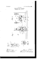
The invention is illustrated in the accompanying drawings, in which- Figure 1 is a front elevation of an induction-coil casing having the vibratory circuitoontroller mounted thereon. Fig. 2 is a side elevation of the front end of the coil-casing with parts of the vibrator in section. Fig. 3 is a detail of the vibratile tongue, and Fig. 4 is a section on line :10 m of Fig. 2.
A is the coil-casing, supposed to contain the usual primary and secondary windings and the magnetic core, one pole of the latter projecting through the front wall of the casing, as seen at a.
a and a are binding-posts for certain of the circuit connections.
To the front wall of the casing is attached a frame comprising the two parts 0 and d, the latter having a bracket extension d and being secured to the former by two screws 0 and 0 These two parts 0 and d serve as a clamp to hold the, fixed end of a vibratile spring tongue or plate 6. For this purpose said tongue, which is of considerable width, is provided at its heel with two notches e c, which straddle the screws 0 0 when the tongue is inserted between the parts 0 d. By
forcing the tongue inward until both screws are seated against the limits of the notches the tongue is automatically alined and requires no further positioning except its adjustment for tension. The tongue is provided with another and much deeper notch or slot 6 for a purpose that will appear hereinafter. The tongue carries at its free end a block of soft iron 6 which is normally presented to the pole a and serves as an armature therefor.
f f are two brackets, andf a bridge for the support of the contaot-screw g. The screw is provided with the usual non-corrodible tip normally engaging a contact g, carried by the tongue 6. Bridge f is hinged at one end to one of the bracketsf, while its other end is removably secured to the other bracket by a thumb-screw f by which means the bridge can be lifted to expose the tip of the screw for cleaning and for making more accessible the tongue 6 when necessary.
For the purpose of adjusting the tension of the tongue a screw 7t is mounted in the bracket d. This screw terminates in a stem h, which passes through the inner end of slot 6 in the tongue and then loosely through a hole in a cross-bar i, the latter being held at a fixed location upon the stem by a nut 71. Beyond the nut the stem has a bearing in a projection from the part c and, if necessary, enters a cavity a in the casing. The cross-bar i is held in a transverse position with respect to the tongue by the end of the part 0, against which it closely lies. Screw a has a left-hand thread, so that when rotated from left to- .right in the natural way the screw instead of working inward will work outward; but the tension of the tongue will be increased, as is the case when the screw is worked inward. Therefore, notwithstanding the fact that an outward movement of the screw accompanies the natural turning movement, the spring is nevertheless stiffened and inexperienced persons as well as others will not require to be specially instructed how to manipulate the adjustment. In rotating the screw the impression gained when it is turned from left to right is that the screw is working inward, and in this case the motion may thei efore be continued so long that the spring will be strained beyond its elastic limit and become perma nently injured. To prevent this, a nut or other stop 0 is fixed upon the shank of the screw to limit the outward movement of the screw to correspond to the limit of the tongues elasticity.
The ridge of the cross-bar bears across the entire width of the tongue, so that there will be no torsion of the tongue when the adj ustment is made. The screw it is self-locking, as shown in Fig. 4, by means of spring-pins set into the bracket (1 and engaging a circular row of sockets under the head of the screw. At each fractional movement of the screw the pins drop into two of the sockets and hold it until it is purposely rotated to a different position.
The advantages of the construction described are these: The spring-tongue can be removed by simply loosening slightly the screws 0 e and drawing the tongue upward and outward, the adjusting-screw and bracket being undisturbed. To replace a tongue, it is passed inward in the same way, the central long slot 6 embracing the stem of the screw and the two slots e e passing around the screws 0 c, the latter then being set up tight. This operation is performed without disturbing the tension-screw or removing bracket d. In other vibrators wherein the tension of the vibratile element is increased by Working the screw inward said element is usually a lever of the third class, wherein the screw bears upon the rearwardly-projecting end; but this requires a longer tongue, and consequently a more cumbersome device. In the construction described the parts are compactly assembled, are manipulated for adjustment in the usual way, and are readily taken apart and put together.
Having described my invention, I claim 1. An induction-coil comprising a vibratile element fixed at one end and carrying an armature at the other, in combination with a tension-screw adapted to positively increase the tension of said element when working outward.
2. An inductioncoil comprising a vibratile element fixed at one end and carrying an armature at the other, in combination with a tension-screw connected to said element to tension the same when moving outward.
3'. An induction-coil comprising a vibratile element fixed at one end and carrying an armature at the other, in combination with a tension-screw having a left-hand thread and connected to positively engage the rear side of said element.
4. In a vibrator for induction-coils, the combination of a vibratile element, an adjusting-screw therefor and means for preventing excessively straining said element when the screw is worked in a direction toincrease the tension thereof.
5. In a vibrator for induction-coils, the combination of a vibratile element, an adjusting-screw therefor and a stop limiting the outward movement of the screw.
6. In an induction-coil, a vibratory spring adapted to be drawn in one direction by the magnetic attraction of the coil, means for increasing the tension of the spring and means for preventing excessive increase of such tension.
7. In an induction-coil, a vibratory spring adapted to be drawn in one direction by the magnetic attraction of the coil, a screw for altering the tension of the spring and means for limiting the longitudinal movement of the screw.
8. In an induction-coil, a vibratory spring adapted to be drawn in one direction by the magnetic attraction of the coil, a screw adapted to give the spring an opposing tension and a stop on said screw limiting its ability to strain the spring.
9. A vibratile element for induction-coils comprising a flat spring having a notch in its fixed end and a screw passing through said notch and clamping the spring fast.
10. A vibratile element for induction-coils comprising a flat spring having a notch in its fixed end, a frame in two parts between which the fixed end of the spring is inserted and a screw passing through the two parts of the frame and the notch in the spring, for the purpose set forth.
11. The combination of the core of an induction-coil, a flat spring carrying an armature arranged in front of said core, said spring having at its fixed end two notches, and two clamping-screws passing through said notches and thereby positioning and clamping the spring.
12. In an induction-coil, a s n'ing-plate, a screw passing transversely through the plate and independently mounted thereof and means whereby the plate is removable without removing the screw.
13. In an induction-coil, a springplate, a screw passing transversely through the plate and independently mounted thereof and adapted to regulate the tension of the spring and means whereby the plate is removable without removing the screw.
14. In an induction-coil, a spring-plate and an adjusting screw mounted in front thereof and having an extension, positively engaging its rear side.
15. In an induction-coil, a spring-plate having an opening and an adjusting-screw passing through said opening and carrying a cross-head engaging the rear side of the plate.
16. In an induction-coil, a vibratory spring In witness whereof I subscribe my signaplate having a notch and an adjusting-screw ture 1n the presence of two witnesses.
for said plate straddled by said notch.
17. In an induction-coil a frame provided with two clamping-screwshnd an adjusting- RICHARD VARLEY 5 screw, in combination with a spring-platel Witnesses:
FRANK S. OBER, VVALDO M. CHAPIN.
having three notches adapted to straddle the three screws respectively.
Priority Applications (1)
| Application Number | Priority Date | Filing Date | Title |
|---|---|---|---|
| US24721505A US809235A (en) | 1905-02-25 | 1905-02-25 | Induction-coil vibrator. |
Applications Claiming Priority (1)
| Application Number | Priority Date | Filing Date | Title |
|---|---|---|---|
| US24721505A US809235A (en) | 1905-02-25 | 1905-02-25 | Induction-coil vibrator. |
Publications (1)
| Publication Number | Publication Date |
|---|---|
| US809235A true US809235A (en) | 1906-01-02 |
Family
ID=2877716
Family Applications (1)
| Application Number | Title | Priority Date | Filing Date |
|---|---|---|---|
| US24721505A Expired - Lifetime US809235A (en) | 1905-02-25 | 1905-02-25 | Induction-coil vibrator. |
Country Status (1)
| Country | Link |
|---|---|
| US (1) | US809235A (en) |
-
1905
- 1905-02-25 US US24721505A patent/US809235A/en not_active Expired - Lifetime
Similar Documents
| Publication | Publication Date | Title |
|---|---|---|
| US809235A (en) | Induction-coil vibrator. | |
| US1906027A (en) | Vibrator control device | |
| US2461360A (en) | Relay | |
| US2385994A (en) | Relay | |
| DE2649522C2 (en) | Electromagnetic relay | |
| US821028A (en) | Removable anvil-contact and bridge-support for electric vibrators. | |
| US1239357A (en) | Relay. | |
| US273728A (en) | Emeey m | |
| US3237205A (en) | Educational device and toy | |
| US909594A (en) | Spark-coil. | |
| US2217073A (en) | Signal device | |
| US82695A (en) | Improvement in telegeaphic insteument | |
| US105975A (en) | Ments | |
| US783207A (en) | Vibrator for induction or spark coils. | |
| US935792A (en) | Telephone-ringer. | |
| US1184017A (en) | Relay. | |
| US877896A (en) | Vibrator. | |
| US738801A (en) | Electromagnet. | |
| US1586855A (en) | Polarized relay | |
| US1493572A (en) | Polarized relay | |
| GB235300A (en) | Improvements in or relating to electro-magnetic apparatus, specially suitable for use as a relay, switch, motor or like device | |
| US836508A (en) | Main-line sounder. | |
| US710946A (en) | Electric bell. | |
| US1696235A (en) | Loud-speaker unit | |
| US614794A (en) | William i |