US809232A - Semi-automatic telephone-exchange system. - Google Patents
Semi-automatic telephone-exchange system. Download PDFInfo
- Publication number
- US809232A US809232A US28171305A US1905281713A US809232A US 809232 A US809232 A US 809232A US 28171305 A US28171305 A US 28171305A US 1905281713 A US1905281713 A US 1905281713A US 809232 A US809232 A US 809232A
- Authority
- US
- United States
- Prior art keywords
- semi
- automatic telephone
- exchange system
- thomson
- patented jan
- Prior art date
- Legal status (The legal status is an assumption and is not a legal conclusion. Google has not performed a legal analysis and makes no representation as to the accuracy of the status listed.)
- Expired - Lifetime
Links
- 230000005540 biological transmission Effects 0.000 description 2
- 238000010586 diagram Methods 0.000 description 2
- 230000001755 vocal effect Effects 0.000 description 2
- 238000004804 winding Methods 0.000 description 2
- 238000010276 construction Methods 0.000 description 1
- 238000010408 sweeping Methods 0.000 description 1
Images


Classifications
-
- H—ELECTRICITY
- H04—ELECTRIC COMMUNICATION TECHNIQUE
- H04Q—SELECTING
- H04Q3/00—Selecting arrangements
Definitions
- My invention relates to telephonic exchange systems of the semi-automatic type that is to say, the type in which the connection and disconnection of subscribers lines at the exchange is effected by means of human operators and in which there is no verbal communication or necessary verbal communication between the subscribers and the operators.
- An important feature in my invention is the subscribers instrument.
- the subscriber having set his instrument in such a manner or to such a position that when transmission to the exchange takes place the number or other indication which corresponds with that manner or position is exhibited or recorded at the exchange, stores up energy by which the callthat is to say,the transmission of the number or other indication can be repeated one or more times, as the operator may desire.
- One great drawback in previously-devised s ti lifll- 11s drawback was that when a mistake was made ordoubt entertained by the operators on receiving the call there was no way of ascertaining the correct call without great loss of time and the employment of special means for the purpose.
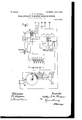
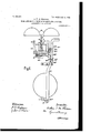
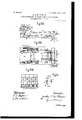
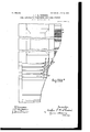
- Figure I shows the circuits and apparatus in diagram of the subscribers instrument.
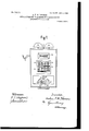
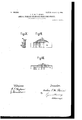
- Fig. II shows the face view of the subscribers .i-1.e.. ams.) L. instrument.
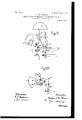
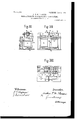
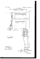
- Fig. III shows the windingsector and detent-magnet of the subscribers instrument.
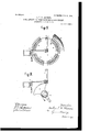
- Fig. IV shows the contacts and revolving arm of subscribers instrument.
- Fig. V shows a detail of the mechanism of the subscribers instrument.
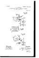
- Fig. VI shows one of the indicating-disks of the subscribers instrument.
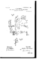
- Figs. VII, VIII, and IX show the mechanical construction of the contacts in the subscribers instrument.
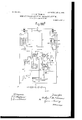
- Figs. X, XI, XII, XIII, XIV, XV show different positions of the parts of the subscribers instrument which operate the annunciator therein.
- XVI, XVII, XVIII, and XIX show, respectively, a side elevation, plan, end elevation, and a detail of the numerical indicator at the central office.
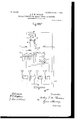
- Figs. XX, XXI, XXII show a vertical cross-section, end elevation, and plan, respectively, of the commutator-relay at the central oflice.
- Figs. XXIILand XXIV show an end and side elevation, respectively, of the retarding-relay at the central office.
- Figs. XXV, XXVI, and XXVII sho w an end elevation, plan, and side elevation of a preferred form of cord-circuit relay.
- XXVIII shows the circuits for an outgoing trunk-line. an incoming trunkline.
- Fig. XXX shows a projecting jack or device to send a current first of one and then of another polarity through the tip of the inserted plug.
- Figs. XXXI XXXI XXXI
- XXXI should be placed side .byside, when they show the circuits in diagram of the entire system.
- Figs. XXXII and XXXII which should be read together, show the two parts of the switchboard.
- FIG. I shows my preferred form of subscribers instrument.
- I store up energy by winding up a clock-spring 1, which is maintained in its wound position by a detent 2."
- the spring is attached in a wellknown manner to a cranked spindle 3, Fig. V, (the crank 4 of which is on the outside of the case,) upon which spindle is mounted a toothed sector 5, driving a pinion 7, connected with the sweeping contact-brush 8, herein after mentioned. Movement of this crank through a definite angular distance winds up the said spring.
- Fig. XXIX shows the circuit for TOC lIO
Landscapes
- Engineering & Computer Science (AREA)
- Computer Networks & Wireless Communication (AREA)
- Exchange Systems With Centralized Control (AREA)
Description
N01. 809,232. PATENTED JAN. 2, 1906.
' A.- T. M; THOMSON.
SEMI-AUTOMATIC TELEPHONE EXGHANGE SYSTEM.
APPLICATION EILED 0.0T. 6. 1905.
l9 SHEETS-SHEET 1 WWW/sa vo Wm;
No. 809,232. PATBNTED JAN. 2, 1906. A. T. M. THOMSON. SEMI-AUTOMATIC TELEPHONE EXCHANGE SYSTEM.
A.PPLIOATION FILED OUT. 6. 1905.
7 l9 SHEETSSHEET 2.
'FigzH.
No. 809,232. PATENTED JAN. 2,1906.
A. T. M. THOMSON; SEMI-AUTOMATIC TELEPHONE EXCHANGE SYSTEM.
APPLICATION FILED OUT 6. 1905.
19 SHEBTSSHEET 3.
110.809.2312. PATBNTED JAN. 2, 1906.
A. T. M. THOMSON. SEMI-AUTOMATIC TELEPHONE EXCHANGE SYSTEM.
APPLICATION FILED 0GT 6.1905.
19 SHEETSSHEET 4.
Fi gv 0O uvvvvvvvl PATENTED JAN. 2, 1906.
A. T. M. THOMSON.
SEMI-AUTOMATIC TELEPHONE EXCHANGE SYSTEM.
APPLICATION FILED 0013.6, 1905 19 SHEETSSHEET 5.
FigtVll.
yuuuuuuuuu No. 809,232. I PATENT-ED JAN. 2, 1906. A. T. M. THOMSON.
SEMI-AUTOMATIC TELEPHONE EXCHANGE SYSTEM.
APPLICATION FILED 001. 6. 1905.
19 SHEETS-SHEET 6.
fifdww No. 809,232. PATENTED JAN. 2, 1906.
A. T. M. THOMSON.
SEMI-AUTOMATIC TELEPHONE EXCHANGE SYSTEM.
APPLICATION FILED OCT 6. 1905.
19 SHEETS-SHEET 7.
FigXl No. 809,232. PATENTED JAN. 2, 1906.
A. T. M. THOMSON. SEMI-AUTOMATIC TELEPHONE EXGHANGE'SYSTEM- APPLICATION FILED OCT 6. 1905.
19 SHEBTS SHEBT B.
Ex CHANGE CALLED (IALLREcEivED I ENGAGED LPLEASE SPEAK.
Nb. 809,232. PATENTED JAN. 2, 1906.
.. A. T. M. THOMSON.
SEMI-AUTOMATIC TELEPHONE EXCHANGE SYSTEM.
APPLICATION FILED OCT, 6. 1905.
19 SHEETS-SHEET 9.
Fi gzXVIH.
F i grXIX.
I Mm
a: I z f 4am fmfmw No- 809,232. PATENTED JAN. 2, 1906.
A. T. M. THOMSON.
SEMI-AUTOMATIC TELEPHONE EXCHANGE SYSTEM.
APPLICATION FILED OCT. 6. 1905.
19 SHEETSSHBBT 10.
FigXXl No. 809,232. PATENTED JAN. 2, 1906.
' A. T. M. THOMSON. SEMI-AUTOMATIC TELEPHONE EXCHANGE SYSTEM.
APPLICATION FILED OOT G. 1905.
' 19 SHEETS-SHEET 11.
V wibmaw= Jrwem/loi,
. No. 809,232. I PATENTED JAN. 2, 1906.
A. T. M. THOMSON. SEMI-AUTOMATIC TELEPHONE EXCHANGE SYSTEM.
APPLICATION FILED OCT 6. 1905.
19 SHEETS-SHEET 12.
Wyn/wow. 7mm. WP wmmm. gm ,3. Z W
PATENTED JAN. 2, 1906. A. T. M., THOMSON.
SEMI-AUTOMATIC TELEPHONE EXCHANGE SYSTEM.
809,232. PATENTED JAN. 2, 1906. A. T. M. THOMSON.
SEMI-AUTOMATIC TELEPHONE EXCHANGE SYSTEM.
APPLICATION FILED 001? 6, 1905.
19 SHEETS-SHBET 14.
Fa g XXX.
' viz/77m M9 HI I [L Mm J I "Wi/W eoow. Jmwwim.
m'm. fwd,
N0- 809,232. PATENTED JAN. 2, 1906.
- A. T. M. THOMSON.
SEMI-AUTOMATIC TELEPHONE EXCHANGE SYSTEM.
APPLICATION FILED 001:. 6. 1905.
19 SHEETSSHEET 15.
2.3 v 01a Calling Lump oal m 16o Q, 012 ZOOQOhm [CGIIIHQ 122 Relay. T
No. 809.232. PATENTED JAN.. 2, 19.06.
I ;,[I.; M.' THOMSON.
SEMI-AUTOMATIC TELEPHONE; EXCHANGE SYSTEM.
' APPLICATION FILED 00T.6. 1905.
19 SHEETS-SHEET16,
H g XXXI" CLEARIN 13S come No. 809,232. PATENTED JAN. 2, 1906. A. T. M. THOMSON. SEMI-AUTOMATIC TELEPHONE EXCHANGE SYSTEM.
APPLICATION FILED OUT. e. 1905.
19 SHEETS-SHEET 17.
' A. T. M. THOMSON.
SEMI-AUTOMATIC TELEPHONE EXCHANGE SYSTEM.
APPLICATION FILED OCT. 6. 1905 19 SHEETS-SHEET 18.
MW F" QIDIQIQIQF FigtXXXlI Mays.
No. 809,232. PATENTED JAN. 2, 1906.
A. T. M. THOMSON. SEMLAUTOMA TIC TELEPHONE EXCHANGE SYSTEM.
APPLICATION FILED OCT. 6, 1905.
19 SHEETS-SHEET l9.
:55 4.2 4; 4p LIEIIIZQIEEIIEII iEIIUIEHDI ZOO l l lL l H I automatic systems is thus overcome.
calling subscriber.
UNITED STATES PATENT OFFICE.
SEMI- AUTOMATIC TELEPHONE-EXCHANGE SYSTEM.
Specification of Letters Patent.
Patented Jan. 2. 1906.
A lication filed October 6, 1905. Serial No. 281,71S.=.;; 'jfifi'i'f;
To all whom, it may concern.-
Be it known that I, ARTHUR T. M. THOM- SON, a subject of the King of Great Britain, and a resident of London, England, have invented a certain new and useful Improvement in Semi Automatic Telephone Exchange Systems, of which the following is a specification.
My invention relates to telephonic exchange systems of the semi-automatic type that is to say, the type in which the connection and disconnection of subscribers lines at the exchange is effected by means of human operators and in which there is no verbal communication or necessary verbal communication between the subscribers and the operators.
An important feature in my invention is the subscribers instrument. By its means when the subscriber having set his instrument in such a manner or to such a position that when transmission to the exchange takes place the number or other indication which corresponds with that manner or position is exhibited or recorded at the exchange, stores up energy by which the callthat is to say,the transmission of the number or other indication can be repeated one or more times, as the operator may desire. One great drawback in previously-devised s ti lifll- 11s drawback was that when a mistake was made ordoubt entertained by the operators on receiving the call there was no way of ascertaining the correct call without great loss of time and the employment of special means for the purpose. The operators had therefore to be provided with telephones, so as to be able to place themselves in telephonic communication with the calling subscriber, in which latter case not only was time lost, but the system ceased for the time being to be semi-automatic. By my invention, however, no telephones need be employed at the exchange and in the event of mistake or doubt the operator after the call need only close the calling-subscriber's circuit through the exchange-indicator in order to have the call repeated (and more than once, if neces sary) by means of the energy stored up by the This storing up of energy may be effected by a mere manual pressure or movement in one direction.
Figure I shows the circuits and apparatus in diagram of the subscribers instrument. Fig. II shows the face view of the subscribers .i-1.e.. ams.) L. instrument. Fig. III shows the windingsector and detent-magnet of the subscribers instrument. Fig. IV shows the contacts and revolving arm of subscribers instrument. Fig. V shows a detail of the mechanism of the subscribers instrument. Fig. VI shows one of the indicating-disks of the subscribers instrument. Figs. VII, VIII, and IX show the mechanical construction of the contacts in the subscribers instrument. Figs. X, XI, XII, XIII, XIV, XV show different positions of the parts of the subscribers instrument which operate the annunciator therein. Figs. XVI, XVII, XVIII, and XIX show, respectively, a side elevation, plan, end elevation, and a detail of the numerical indicator at the central office. Figs. XX, XXI, XXII show a vertical cross-section, end elevation, and plan, respectively, of the commutator-relay at the central oflice. Figs. XXIILand XXIV show an end and side elevation, respectively, of the retarding-relay at the central office. Figs. XXV, XXVI, and XXVII sho w an end elevation, plan, and side elevation of a preferred form of cord-circuit relay. Fig. XXVIII shows the circuits for an outgoing trunk-line. an incoming trunkline. Fig. XXX shows a projecting jack or device to send a current first of one and then of another polarity through the tip of the inserted plug. Figs. XXXI XXXI", XXXI should be placed side .byside, when they show the circuits in diagram of the entire system. Figs. XXXII and XXXII which should be read together, show the two parts of the switchboard.
I shall now proceed to describe my subscribers instrument, (shown diagrammatically in Fig. 1,) and then I'shall describe the appliances which I employ at the exchange in connection therewith.
T he subscribers instrument, (Figs. I to XV.) In Figs. II to XV I show my preferred form of subscribers instrument. Here I store up energy by winding up a clock-spring 1, which is maintained in its wound position by a detent 2." For the purpose of such winding up the spring is attached in a wellknown manner to a cranked spindle 3, Fig. V, (the crank 4 of which is on the outside of the case,) upon which spindle is mounted a toothed sector 5, driving a pinion 7, connected with the sweeping contact-brush 8, herein after mentioned. Movement of this crank through a definite angular distance winds up the said spring. The function of this spring Fig. XXIX shows the circuit for TOC lIO
Priority Applications (1)
| Application Number | Priority Date | Filing Date | Title |
|---|---|---|---|
| US28171305A US809232A (en) | 1905-10-06 | 1905-10-06 | Semi-automatic telephone-exchange system. |
Applications Claiming Priority (1)
| Application Number | Priority Date | Filing Date | Title |
|---|---|---|---|
| US28171305A US809232A (en) | 1905-10-06 | 1905-10-06 | Semi-automatic telephone-exchange system. |
Publications (1)
| Publication Number | Publication Date |
|---|---|
| US809232A true US809232A (en) | 1906-01-02 |
Family
ID=2877713
Family Applications (1)
| Application Number | Title | Priority Date | Filing Date |
|---|---|---|---|
| US28171305A Expired - Lifetime US809232A (en) | 1905-10-06 | 1905-10-06 | Semi-automatic telephone-exchange system. |
Country Status (1)
| Country | Link |
|---|---|
| US (1) | US809232A (en) |
-
1905
- 1905-10-06 US US28171305A patent/US809232A/en not_active Expired - Lifetime
Similar Documents
| Publication | Publication Date | Title |
|---|---|---|
| US809232A (en) | Semi-automatic telephone-exchange system. | |
| USRE12565E (en) | Reissued nov | |
| US789350A (en) | Interconnecting telephone system. | |
| US606620A (en) | brown | |
| US813230A (en) | Service-meter for telephone-exchanges. | |
| US306361A (en) | Individual-call instrument for telephones | |
| US1439723A (en) | Numbering system for automatic telephone exchanges | |
| US1074677A (en) | Enumeration of telephone-calls. | |
| US1025378A (en) | Telephone-service meter. | |
| US852004A (en) | Automatic telephone switch system. | |
| US1044538A (en) | Selective apparatus for party-telephones. | |
| US239557A (en) | Electrical switch-board | |
| US1233837A (en) | Telephone-exchange system. | |
| US1133373A (en) | Subscriber-controlled switching apparatus for telephone-exchange systems. | |
| US728350A (en) | Telephony. | |
| US1147389A (en) | Automatic telephone system. | |
| US1077753A (en) | Switchboard circuits and apparatus for telephones. | |
| US921429A (en) | Means for counting conversations at telephone-exchanges. | |
| US840544A (en) | Party-line-telephone mechanism. | |
| US1185938A (en) | Telephone-exchange. | |
| US1209826A (en) | Telephone system. | |
| US691229A (en) | Individual telephone switch and lock-out mechanism for interconnecting lines. | |
| US1142080A (en) | Telephone attachment. | |
| US980883A (en) | Telephone-exchange. | |
| USRE12240E (en) | Reissued july |