US8092037B2 - Fluorescent light fixture retrofit kit - Google Patents
Fluorescent light fixture retrofit kit Download PDFInfo
- Publication number
- US8092037B2 US8092037B2 US12/460,902 US46090209A US8092037B2 US 8092037 B2 US8092037 B2 US 8092037B2 US 46090209 A US46090209 A US 46090209A US 8092037 B2 US8092037 B2 US 8092037B2
- Authority
- US
- United States
- Prior art keywords
- reflector
- fixture
- winged
- lamp
- retrofit kit
- Prior art date
- Legal status (The legal status is an assumption and is not a legal conclusion. Google has not performed a legal analysis and makes no representation as to the accuracy of the status listed.)
- Expired - Fee Related, expires
Links
- 238000005286 illumination Methods 0.000 claims description 6
- 239000002184 metal Substances 0.000 claims description 5
- 239000003973 paint Substances 0.000 claims description 3
- 238000012360 testing method Methods 0.000 description 11
- 238000009434 installation Methods 0.000 description 5
- 238000000034 method Methods 0.000 description 3
- 238000013461 design Methods 0.000 description 2
- 239000011248 coating agent Substances 0.000 description 1
- 238000000576 coating method Methods 0.000 description 1
- 239000002320 enamel (paints) Substances 0.000 description 1
- 238000012986 modification Methods 0.000 description 1
- 230000004048 modification Effects 0.000 description 1
- 238000005375 photometry Methods 0.000 description 1
- 238000010561 standard procedure Methods 0.000 description 1
- 230000000007 visual effect Effects 0.000 description 1
Images


Classifications
-
- F—MECHANICAL ENGINEERING; LIGHTING; HEATING; WEAPONS; BLASTING
- F21—LIGHTING
- F21V—FUNCTIONAL FEATURES OR DETAILS OF LIGHTING DEVICES OR SYSTEMS THEREOF; STRUCTURAL COMBINATIONS OF LIGHTING DEVICES WITH OTHER ARTICLES, NOT OTHERWISE PROVIDED FOR
- F21V7/00—Reflectors for light sources
- F21V7/005—Reflectors for light sources with an elongated shape to cooperate with linear light sources
-
- F—MECHANICAL ENGINEERING; LIGHTING; HEATING; WEAPONS; BLASTING
- F21—LIGHTING
- F21S—NON-PORTABLE LIGHTING DEVICES; SYSTEMS THEREOF; VEHICLE LIGHTING DEVICES SPECIALLY ADAPTED FOR VEHICLE EXTERIORS
- F21S8/00—Lighting devices intended for fixed installation
- F21S8/04—Lighting devices intended for fixed installation intended only for mounting on a ceiling or the like overhead structures
- F21S8/06—Lighting devices intended for fixed installation intended only for mounting on a ceiling or the like overhead structures by suspension
-
- F—MECHANICAL ENGINEERING; LIGHTING; HEATING; WEAPONS; BLASTING
- F21—LIGHTING
- F21Y—INDEXING SCHEME ASSOCIATED WITH SUBCLASSES F21K, F21L, F21S and F21V, RELATING TO THE FORM OR THE KIND OF THE LIGHT SOURCES OR OF THE COLOUR OF THE LIGHT EMITTED
- F21Y2103/00—Elongate light sources, e.g. fluorescent tubes
-
- Y—GENERAL TAGGING OF NEW TECHNOLOGICAL DEVELOPMENTS; GENERAL TAGGING OF CROSS-SECTIONAL TECHNOLOGIES SPANNING OVER SEVERAL SECTIONS OF THE IPC; TECHNICAL SUBJECTS COVERED BY FORMER USPC CROSS-REFERENCE ART COLLECTIONS [XRACs] AND DIGESTS
- Y02—TECHNOLOGIES OR APPLICATIONS FOR MITIGATION OR ADAPTATION AGAINST CLIMATE CHANGE
- Y02B—CLIMATE CHANGE MITIGATION TECHNOLOGIES RELATED TO BUILDINGS, e.g. HOUSING, HOUSE APPLIANCES OR RELATED END-USER APPLICATIONS
- Y02B20/00—Energy efficient lighting technologies, e.g. halogen lamps or gas discharge lamps
- Y02B20/30—Semiconductor lamps, e.g. solid state lamps [SSL] light emitting diodes [LED] or organic LED [OLED]
Definitions
- the present invention relates to a retrofit kit for tubular fluorescent lamp fixtures.
- the present invention relates to the use of a retrofit kit which is designed to delamp fixtures using two T12 lamps to a single T8 lamp. It can also be used to delamp from two T8's to a single T8 due to the high efficiency and other improvements offered by kit. Similar 4-lamp to 2-lamp retrofit kits are feasible although they will not be detailed in this invention.
- a key component of the retrofit kit is an arched (preferably trapezoidal) socket bar which is used at both ends of the fixture housing. It secures the lamp socket as well as providing a rigid anchor point at each end of the fixture for a concave reflector, preferably a two wing reflector, which is carefully formed to enhance both efficiency as well as uniformity of light distribution.
- This arched socket bar has bent tabs which snap into socket bar slots at the sides of the housing by entering from the outside of the vertical sides. To further enhance the attachment, sheet metal screws can be used through holes in the vertical sides of the socket bar into the housing sides.
- a major purpose of the arched socket bar besides the structural aspects, is the precise placement of the fluorescent lamp relative to the concave wing surfaces of the reflector. This is a key element of achieving the desired light distribution.
- the arched socket bar also contributes to the ease of installation of this retrofit kit.
- the reflector is formed to provide a narrow horizontal central section and two sloped adjacent sections which contribute to its rigidity even if formed of relatively thin sheet metal. Since the high efficiency replacement ballast is not supported by the reflector, but attached inside the housing, this also lessens the required structural integrity. The light weight, while reducing cost, also contributes to ease of installation; it is secured to the arched socket bar by a single quarter-turn screw at each end.
- the sloped central sections on either side of the central horizontal section are extended by several linear facets bent at precise angles forming the generally concave wings.
- a highly reflective white enamel paint is used in lieu of a specular coating. This reduces cost while supporting over a 90% overall efficiency. By design, approximately 6% uplighting is achieved by this design.
- a three page luminaire test report is included in the drawing section to support these contentions.
- FIG. 1 is a perspective view of the arched socket bar used at each end of the housing of this retrofit kit.
- FIG. 2 shows three orthographic views of the arched socket bar of FIG. 1 (note these views are inverted with respect to FIG. 1 ).
- FIG. 3A is a retrofit kit instruction sheet with parts.
- FIG. 3B is a detailed view of a socket bar, socket bar slot and lamp socket of the retrofit kit of FIG. 3A .
- FIG. 4 an end view of a completed retrofit kit showing the reflector contour details as well as the geometric relations between socket bar, housing, and lamp socket.
- FIG. 5 is a perspective detail of one end of an installed retrofit kit showing the location of the ballast access cover (for clarity, the lamp is not shown in this view).
- FIG. 6 is the test results on a first page of the luminaire test report showing, in part, a Polar Candela Plot.
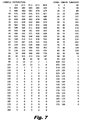
- FIG. 7 is the test results on a second page of the luminaire test report with a Candela Distribution Table and a Zonal Lumen Summary at 5 degree increments.
- FIG. 8 is the test results on a third page of the luminaire test report showing Coefficients of Utilization for a variety of space configurations (zonal cavity method) and a variety of ceiling and wall reflectance values.
- FIGS. 1 and 2 describe the shape of the arched (trapezoidal) socket bar 1 used at each end of the fixture housing. It is a key structural element as well as a performance element which precisely fixes the location of the lamp socket in relation to the reflector. As a die formed sheet metal part, it is inexpensive to produce. It has sloping sides 15 on either side of horizontal section 16 . Vertical walls 5 hug the outside vertical surfaces of the housing while tabs 7 engage the socket bar slots on the sides of the housing. Holes 6 can be used to add attachment screws from socket bar 1 to the housing. A cutout region with side edges 9 used as rails to engage the lamp socket (a type which mounts by side grooves) is part of the horizontal section.
- Dimples 10 are used to engage the side grooves of the lamp socket for a tight fit.
- An elongated hole 14 with rounded edges is used as a stiffening feature.
- Item 12 is an embossed section with a punched slotted hole to accommodate a 1 ⁇ 4-turn screw used to support one end of the reflector.
- FIGS. 3A and 3B detail the six simple steps required for installation.
- the socket bar 1 , socket bar slot 21 and lamp socket 22 are shown in a detail in FIG. 3B , whereby the socket bar is inserted into an outside surface slot of the housing 20 , with the socket 22 for the lamp 25 descending downward therefrom.
- FIG. 3A shows housing 20 , ballast 23 , reflector 30 , lamp 25 and ballast cover 31 in addition to other parts already discussed.
- Installation includes the following steps:
- FIG. 4 shows a detailed end view of double wing reflector 30 and its relation to arched socket bar 1 , socket 22 , and housing 20 .
- Socket bar 1 wraps around a lower portion of housing 20 from underneath. Note tabs 7 fitting from the outside through the sides of housing 20 .
- the relation of the position of socket 22 and the size and angle of each facet in concave sections 33 contribute to the superior efficiency and uniformity of light distribution of this retrofit kit fixture. While angles may vary, preferably each facet forming the concave reflector wing 33 extends at an angle downward from each adjacent facet, starting with the first fact closest to housing 20 .
- the first facet extends near a respective sloped lower portion of socket bar 1 , which is at an angle of about 160 degrees off of an imaginary horizontal line where the sloped portion of socket bar 1 meets the vertical portion of socket bar 1 .
- the next subsequent facet extends downward about 175 degrees off of the first facet.
- Subsequent facets preferably about five facets, extend about 170 degrees off of the closest facet on the side of the subsequent facet nearest to the socket bar 1 and housing 20 , ending in a distal end of winged reflector 33 .
- central horizontal section 34 and sloped adjacent sections 35 of reflector 30 form the bottom cover of housing 20 .
- the optimal position of the lamp within socket 22 is below the imaginary horizontal plane formed by the respective opposite distal ends of concave sections 33 of the winged reflector 30 . Additionally, the distal ends of each respective concave winged position 33 of winged reflector 30 are bent upward at an angle. The lowered position of the lamp within socket 22 and the bent distal ends of the concave winged reflector also assist in providing uplight, as well as downward illumination of light reflected by the respective concave winged portions 33 of the winged reflector 30 .
- FIG. 5 shows a detail of the completed kit (minus lamp) showing the mounting screw 40 attaching reflector 30 to arched socket bar 1 . Ballast cover 31 secured by 1 ⁇ 4 turn wing screw 41 is also shown.
- FIGS. 6-8 constitute a Luminaire Test Report conducted by Luminaire Testing Laboratory Inc of Allentown, Pa. on Applicants' behalf in standard format which is used to compare fixtures of various types using the same testing techniques.
- the total reflectance of the reflector paint is shown as 92.2%; the total luminaire efficiency is shown as 92.4%.
Landscapes
- Engineering & Computer Science (AREA)
- General Engineering & Computer Science (AREA)
- Non-Portable Lighting Devices Or Systems Thereof (AREA)
- Securing Globes, Refractors, Reflectors Or The Like (AREA)
Abstract
Description
Claims (25)
Priority Applications (1)
| Application Number | Priority Date | Filing Date | Title |
|---|---|---|---|
| US12/460,902 US8092037B2 (en) | 2008-08-22 | 2009-07-24 | Fluorescent light fixture retrofit kit |
Applications Claiming Priority (2)
| Application Number | Priority Date | Filing Date | Title |
|---|---|---|---|
| US12/229,390 US7942545B2 (en) | 2008-08-22 | 2008-08-22 | Ballast access hatch in reflector |
| US12/460,902 US8092037B2 (en) | 2008-08-22 | 2009-07-24 | Fluorescent light fixture retrofit kit |
Related Parent Applications (1)
| Application Number | Title | Priority Date | Filing Date |
|---|---|---|---|
| US12/229,390 Continuation-In-Part US7942545B2 (en) | 2008-08-22 | 2008-08-22 | Ballast access hatch in reflector |
Publications (2)
| Publication Number | Publication Date |
|---|---|
| US20100046214A1 US20100046214A1 (en) | 2010-02-25 |
| US8092037B2 true US8092037B2 (en) | 2012-01-10 |
Family
ID=41696213
Family Applications (1)
| Application Number | Title | Priority Date | Filing Date |
|---|---|---|---|
| US12/460,902 Expired - Fee Related US8092037B2 (en) | 2008-08-22 | 2009-07-24 | Fluorescent light fixture retrofit kit |
Country Status (1)
| Country | Link |
|---|---|
| US (1) | US8092037B2 (en) |
Cited By (7)
| Publication number | Priority date | Publication date | Assignee | Title |
|---|---|---|---|---|
| USD671258S1 (en) * | 2011-09-28 | 2012-11-20 | Pinnacle Architectural Lighting | Light fixture lens |
| US20130343048A1 (en) * | 2012-06-01 | 2013-12-26 | Gilles Dumont | Light reflector for a horticultural device |
| US9822937B2 (en) | 2014-06-16 | 2017-11-21 | Abl Ip Holding Llc | Light engine retrofit kit and method for installing same |
| US10010729B1 (en) | 2017-03-01 | 2018-07-03 | Hyprum Llc | Harness having a deployable rappelling assembly |
| US10267497B2 (en) | 2015-02-04 | 2019-04-23 | Abl Ip Holding Llc | Easy install light engine retrofit kit and method for using same |
| US10883682B1 (en) * | 2020-03-20 | 2021-01-05 | Fintronx, Llc | Lighting fixtures having mounting structure openings and coverings |
| US11959631B2 (en) | 2007-12-21 | 2024-04-16 | Appalachian Lighting Systems, Inc. | Lighting fixture |
Families Citing this family (5)
| Publication number | Priority date | Publication date | Assignee | Title |
|---|---|---|---|---|
| EP2453165B1 (en) * | 2010-11-12 | 2017-09-06 | LG Innotek Co., Ltd. | Lighting device |
| US8911114B2 (en) * | 2011-11-22 | 2014-12-16 | American Green Technology | Retrofit reflector for a fixture |
| CN102661583B (en) * | 2012-05-19 | 2013-10-30 | 区其富 | Lamp fitting construction members and ceiling lamp using same |
| CN102661584B (en) * | 2012-05-19 | 2014-05-07 | 区其富 | Lamp support constructional element and ceiling lamp using same |
| JP6312611B2 (en) * | 2015-01-26 | 2018-04-18 | アイリスオーヤマ株式会社 | LED lighting device |
Citations (20)
| Publication number | Priority date | Publication date | Assignee | Title |
|---|---|---|---|---|
| US2360448A (en) | 1943-06-07 | 1944-10-17 | Harry U Schockett | Fluorescent lamp fixture |
| GB744252A (en) | 1953-03-12 | 1956-02-01 | Strong Electric Corp Great Bri | Improvements in and relating to electric light fittings and their reflectors |
| GB820976A (en) | 1957-01-18 | 1959-09-30 | Philips Electrical Ind Ltd | Improvements in or relating to fluorescent lighting fittings |
| GB1424206A (en) | 1972-05-09 | 1976-02-11 | Erco Leuchten | Built-in ceiling lighting unit |
| US4599684A (en) * | 1985-03-11 | 1986-07-08 | Lee Richard H | Light reflector system |
| GB2188139A (en) | 1986-03-17 | 1987-09-23 | Peter Christopher Jo Gallagher | Improving the efficiency of lighting apparatus |
| US4799134A (en) | 1986-07-15 | 1989-01-17 | Spencer McGrath | Optical reflector system for fluorescent lighting fixtures |
| US4814954A (en) * | 1987-12-24 | 1989-03-21 | Spitz Russell W | Rigid lightweight fluorescent fixture |
| US4974131A (en) | 1988-11-21 | 1990-11-27 | Paradiso Jerome J | Modular fluorescent lighting system |
| US5207504A (en) | 1991-07-03 | 1993-05-04 | Swift Gerald R | Method and apparatus for tuning strip flourescent light fixtures |
| US5412551A (en) * | 1993-11-15 | 1995-05-02 | Mark Lighting Co., Inc. | Luminaire fixture |
| US5414604A (en) * | 1993-11-09 | 1995-05-09 | Minnesota Mining And Manufacturing Company | Light reflector with edge illumination |
| US5473522A (en) | 1994-07-25 | 1995-12-05 | Sportlite, Inc. | Modular luminaire |
| US5757112A (en) * | 1996-03-22 | 1998-05-26 | U.S. Philips Corporation | Irradiation device |
| WO2000042820A2 (en) | 1999-01-14 | 2000-07-20 | Es Energy Technologies, L.L.C. | Light fixture retrofit system |
| US6210019B1 (en) | 1998-11-04 | 2001-04-03 | Osram Sylvania Inc. | Method for retrofitting and retrofit kit for fluorescent lighting fixture |
| US20010050850A1 (en) | 2000-06-07 | 2001-12-13 | Carlton Plunk | Retrofit recessed fluorescent strip fixture and method |
| US20020136001A1 (en) | 2001-03-21 | 2002-09-26 | Lsi Midwest Lighting Inc. | Low-profile fluorescent luminaire and methods of installation |
| US6523975B1 (en) * | 2001-08-01 | 2003-02-25 | Jason V. Plourde | Adjustable support and method of modifying a flourescent light fixture |
| US6984131B2 (en) | 2002-03-12 | 2006-01-10 | Westinghouse Lighting Corporation | Lamp tube conversion apparatus |
-
2009
- 2009-07-24 US US12/460,902 patent/US8092037B2/en not_active Expired - Fee Related
Patent Citations (21)
| Publication number | Priority date | Publication date | Assignee | Title |
|---|---|---|---|---|
| US2360448A (en) | 1943-06-07 | 1944-10-17 | Harry U Schockett | Fluorescent lamp fixture |
| GB744252A (en) | 1953-03-12 | 1956-02-01 | Strong Electric Corp Great Bri | Improvements in and relating to electric light fittings and their reflectors |
| GB820976A (en) | 1957-01-18 | 1959-09-30 | Philips Electrical Ind Ltd | Improvements in or relating to fluorescent lighting fittings |
| GB1424206A (en) | 1972-05-09 | 1976-02-11 | Erco Leuchten | Built-in ceiling lighting unit |
| US4599684A (en) * | 1985-03-11 | 1986-07-08 | Lee Richard H | Light reflector system |
| GB2172390A (en) | 1985-03-11 | 1986-09-17 | Specuflex Inc | Light reflector system |
| GB2188139A (en) | 1986-03-17 | 1987-09-23 | Peter Christopher Jo Gallagher | Improving the efficiency of lighting apparatus |
| US4799134A (en) | 1986-07-15 | 1989-01-17 | Spencer McGrath | Optical reflector system for fluorescent lighting fixtures |
| US4814954A (en) * | 1987-12-24 | 1989-03-21 | Spitz Russell W | Rigid lightweight fluorescent fixture |
| US4974131A (en) | 1988-11-21 | 1990-11-27 | Paradiso Jerome J | Modular fluorescent lighting system |
| US5207504A (en) | 1991-07-03 | 1993-05-04 | Swift Gerald R | Method and apparatus for tuning strip flourescent light fixtures |
| US5414604A (en) * | 1993-11-09 | 1995-05-09 | Minnesota Mining And Manufacturing Company | Light reflector with edge illumination |
| US5412551A (en) * | 1993-11-15 | 1995-05-02 | Mark Lighting Co., Inc. | Luminaire fixture |
| US5473522A (en) | 1994-07-25 | 1995-12-05 | Sportlite, Inc. | Modular luminaire |
| US5757112A (en) * | 1996-03-22 | 1998-05-26 | U.S. Philips Corporation | Irradiation device |
| US6210019B1 (en) | 1998-11-04 | 2001-04-03 | Osram Sylvania Inc. | Method for retrofitting and retrofit kit for fluorescent lighting fixture |
| WO2000042820A2 (en) | 1999-01-14 | 2000-07-20 | Es Energy Technologies, L.L.C. | Light fixture retrofit system |
| US20010050850A1 (en) | 2000-06-07 | 2001-12-13 | Carlton Plunk | Retrofit recessed fluorescent strip fixture and method |
| US20020136001A1 (en) | 2001-03-21 | 2002-09-26 | Lsi Midwest Lighting Inc. | Low-profile fluorescent luminaire and methods of installation |
| US6523975B1 (en) * | 2001-08-01 | 2003-02-25 | Jason V. Plourde | Adjustable support and method of modifying a flourescent light fixture |
| US6984131B2 (en) | 2002-03-12 | 2006-01-10 | Westinghouse Lighting Corporation | Lamp tube conversion apparatus |
Cited By (8)
| Publication number | Priority date | Publication date | Assignee | Title |
|---|---|---|---|---|
| US11959631B2 (en) | 2007-12-21 | 2024-04-16 | Appalachian Lighting Systems, Inc. | Lighting fixture |
| USD671258S1 (en) * | 2011-09-28 | 2012-11-20 | Pinnacle Architectural Lighting | Light fixture lens |
| US20130343048A1 (en) * | 2012-06-01 | 2013-12-26 | Gilles Dumont | Light reflector for a horticultural device |
| US9822937B2 (en) | 2014-06-16 | 2017-11-21 | Abl Ip Holding Llc | Light engine retrofit kit and method for installing same |
| US10508777B2 (en) | 2014-06-16 | 2019-12-17 | Abl Ip Holding Llc | Light engine retrofit kit and method for installing same |
| US10267497B2 (en) | 2015-02-04 | 2019-04-23 | Abl Ip Holding Llc | Easy install light engine retrofit kit and method for using same |
| US10010729B1 (en) | 2017-03-01 | 2018-07-03 | Hyprum Llc | Harness having a deployable rappelling assembly |
| US10883682B1 (en) * | 2020-03-20 | 2021-01-05 | Fintronx, Llc | Lighting fixtures having mounting structure openings and coverings |
Also Published As
| Publication number | Publication date |
|---|---|
| US20100046214A1 (en) | 2010-02-25 |
Similar Documents
| Publication | Publication Date | Title |
|---|---|---|
| US8092037B2 (en) | Fluorescent light fixture retrofit kit | |
| US8297804B2 (en) | Recessed light fixture having integrally formed mounting tracks | |
| US8672508B2 (en) | Scalable LED sconce light | |
| US6585396B1 (en) | Fluorescent hanging light fixture | |
| US8142057B2 (en) | Recessed LED downlight | |
| US8070328B1 (en) | LED downlight | |
| CA2346580C (en) | Asymmetric distribution luminaire | |
| US20050237746A1 (en) | Surface and recess mountable lighting fixture | |
| US10240760B1 (en) | Horizontal light guide based lighting fixture | |
| KR101425014B1 (en) | LED lighting | |
| US10415800B2 (en) | Light fixtures with integrated features | |
| US20110310603A1 (en) | Light fixtures | |
| CA2688640C (en) | Retro-fit luminaire assembly | |
| US6007217A (en) | Luminaire assembly mounting system | |
| US20180051854A1 (en) | Retrofit kit and methods for conversion of fluorescent light assemblies to led assemblies | |
| US20140078731A1 (en) | Led socket adapter assembly | |
| US12253241B2 (en) | Sloped ceiling adjustable light fixture | |
| US7837347B2 (en) | Reversible light reflector | |
| US20120262920A1 (en) | Lighting Assembly for New and Retrofitting Applications | |
| US7682046B2 (en) | Light fixture with lamp adjustment assembly | |
| KR200450149Y1 (en) | Lamp holder for downlight with rotation and angle adjustment | |
| JP2003187632A (en) | Downlight fixture with adjustable reflection efficiency for multiple types of lamps and method of installation | |
| KR101663052B1 (en) | LED ceiling lights | |
| CN224003615U (en) | A reflective paper fixing device for lamps and a lamp using the same. | |
| US10253932B2 (en) | Lighting system configured to fit with a box or strip housing and a method of fitting a lighting system with a box or strip housing |
Legal Events
| Date | Code | Title | Description |
|---|---|---|---|
| AS | Assignment |
Owner name: OPTIMUM LIGHTING, LLC, NORTH CAROLINA Free format text: ASSIGNMENT OF ASSIGNORS INTEREST;ASSIGNORS:KASSAY, CHARLES E.;PANE, SUZANNE M.;KASSAY, MARC A.;AND OTHERS;REEL/FRAME:026025/0103 Effective date: 20101028 Owner name: PHILIPS ELECTRONICS NORTH AMERICA CORPORATION, MAS Free format text: ASSIGNMENT OF ASSIGNORS INTEREST;ASSIGNOR:OPTIMUM LIGHTING, LLC;REEL/FRAME:026025/0327 Effective date: 20110104 |
|
| STCF | Information on status: patent grant |
Free format text: PATENTED CASE |
|
| REMI | Maintenance fee reminder mailed | ||
| FPAY | Fee payment |
Year of fee payment: 4 |
|
| SULP | Surcharge for late payment | ||
| AS | Assignment |
Owner name: PHILIPS ELECTRONICS NORTH AMERICA CORPORATION, NEW Free format text: ASSIGNMENT OF ASSIGNORS INTEREST;ASSIGNOR:OPTIMUM LIGHTING, LLC;REEL/FRAME:041759/0482 Effective date: 20110104 |
|
| FEPP | Fee payment procedure |
Free format text: MAINTENANCE FEE REMINDER MAILED (ORIGINAL EVENT CODE: REM.); ENTITY STATUS OF PATENT OWNER: LARGE ENTITY |
|
| LAPS | Lapse for failure to pay maintenance fees |
Free format text: PATENT EXPIRED FOR FAILURE TO PAY MAINTENANCE FEES (ORIGINAL EVENT CODE: EXP.); ENTITY STATUS OF PATENT OWNER: LARGE ENTITY |
|
| STCH | Information on status: patent discontinuation |
Free format text: PATENT EXPIRED DUE TO NONPAYMENT OF MAINTENANCE FEES UNDER 37 CFR 1.362 |
|
| FP | Expired due to failure to pay maintenance fee |
Effective date: 20200110 |