JP6312611B2 - LED lighting device - Google Patents

LED lighting device Download PDF

Info

Publication number
JP6312611B2
JP6312611B2 JP2015012266A JP2015012266A JP6312611B2 JP 6312611 B2 JP6312611 B2 JP 6312611B2 JP 2015012266 A JP2015012266 A JP 2015012266A JP 2015012266 A JP2015012266 A JP 2015012266A JP 6312611 B2 JP6312611 B2 JP 6312611B2
Authority
JP
Japan
Prior art keywords
led
instrument body
reflecting plate
plate
recess
Prior art date
Legal status (The legal status is an assumption and is not a legal conclusion. Google has not performed a legal analysis and makes no representation as to the accuracy of the status listed.)
Active
Application number
JP2015012266A
Other languages
Japanese (ja)
Other versions
JP2015179664A (en
JP2015179664A5 (en
Inventor
直輝 谷藤
直輝 谷藤
瑠津子 秋山
瑠津子 秋山
Current Assignee (The listed assignees may be inaccurate. Google has not performed a legal analysis and makes no representation or warranty as to the accuracy of the list.)
Iris Ohyama Inc
Original Assignee
Iris Ohyama Inc
Priority date (The priority date is an assumption and is not a legal conclusion. Google has not performed a legal analysis and makes no representation as to the accuracy of the date listed.)
Filing date
Publication date
Application filed by Iris Ohyama Inc filed Critical Iris Ohyama Inc
Priority to JP2015012266A priority Critical patent/JP6312611B2/en
Publication of JP2015179664A publication Critical patent/JP2015179664A/en
Publication of JP2015179664A5 publication Critical patent/JP2015179664A5/ja
Application granted granted Critical
Publication of JP6312611B2 publication Critical patent/JP6312611B2/en
Active legal-status Critical Current
Anticipated expiration legal-status Critical

Links

Images

Description

本発明は、LED(Light Emitting Diode:発光ダイオード)照明装置に関する。   The present invention relates to an LED (Light Emitting Diode) illumination device.

この種の従来技術としては、例えば特許文献1に開示されたものがある。即ち、特許文献1には、板金製の器具本体に板金製の反射笠を止め金具にて取り付けた照明器具が開示されている。この器具本体に、ソケットを備えた灯具保持具が取り付けられる。   As this type of prior art, for example, there is one disclosed in Patent Document 1. That is, Patent Literature 1 discloses a lighting fixture in which a sheet metal reflecting shade is attached to a sheet metal fixture body with a stopper. A lamp holder having a socket is attached to the fixture body.

特許第4045788号Patent No. 4045788

特許文献1に開示された照明器具では、器具本体と灯具保持具との間に反射笠や、反射笠を器具本体に固定する止め金具及びラッチが配置される。器具本体と、止め金具と、反射笠及びラッチが全て上下方向(即ち、天井から床面に向かう方向)で並ぶため、照明器具が厚くなりがちであるという課題があった。
そこで、この発明はこのような事情に鑑みてなされたものであって、厚みを薄くできるようにしたLED照明装置の提供を目的とする。
In the luminaire disclosed in Patent Document 1, a reflective shade, a stopper and a latch for fixing the reflective shade to the fixture body are arranged between the fixture body and the lamp holder. Since the fixture main body, the stopper, the reflective shade and the latch are all arranged in the vertical direction (that is, the direction from the ceiling to the floor), there is a problem that the lighting fixture tends to be thick.
Therefore, the present invention has been made in view of such circumstances, and an object of the present invention is to provide an LED lighting device that can be made thin.

上記課題を解決するために、本発明の一態様に係るLED照明装置は、LEDユニットを支持し、該LEDユニットを支持する支持面の反対側の少なくとも一部が被取付部に対する取付面となる器具本体と、前記器具本体の側面に面接触した状態で取り付けられ、前記LEDユニットが発光する光を予め設定した方向へ反射する反射板と、を備え、前記反射板は、前記側面の面接触する領域のうち、前記取付面に近い第1の縁部と前記取付面から遠い第2の縁部との間の中心部よりも該第2の縁部に近い位置で固定されることを特徴とする。   In order to solve the above problems, an LED lighting device according to an aspect of the present invention supports an LED unit, and at least a part of the opposite side of the support surface that supports the LED unit serves as a mounting surface for the mounted portion. An instrument body, and a reflector that is mounted in surface contact with the side surface of the instrument body and reflects light emitted from the LED unit in a preset direction, the reflector plate being in surface contact with the side surface. Of the region to be fixed, the first edge portion close to the mounting surface and the second edge portion far from the mounting surface are fixed at a position closer to the second edge portion than the center portion. And

また、上記のLED照明装置において、前記側面のうち前記取付面の側に段差部が形成されており、前記段差部に前記反射板が掛止されることを特徴としてもよい。
また、上記のLED照明装置において、前記反射板は、前記位置に通される締結部材によって前記器具本体の側に押圧されて固定されることを特徴としてもよい。
また、上記のLED照明装置において、前記段差部に開口部が設けられており、前記反射板の縁部から突き出た突片が前記開口部に差し込まれることを特徴としてもよい。
Moreover, said LED lighting apparatus WHEREIN: The level | step-difference part is formed in the said attachment surface side among the said side surfaces, It is good also considering the said reflecting plate being latched by the said level | step-difference part.
Moreover, said LED illuminating device WHEREIN: The said reflecting plate is pressed and fixed to the said instrument main body side by the fastening member penetrated to the said position, It is good also considering the above-mentioned as a characteristic.
Moreover, said LED illuminating device WHEREIN: The opening part is provided in the said level | step-difference part, It is good also considering the protrusion protruding from the edge of the said reflecting plate being inserted in the said opening part.

また、上記のLED照明装置において、前記器具本体の前記支持面の側で、該器具本体
と前記反射板との接触部が同一平面内にあることを特徴としてもよい。
また、上記のLED照明装置において、前記器具本体は前記支持面の側に凹部を有し、
前記凹部に収容されるLEDユニットをさらに備えることを特徴としてもよい。
本発明の別の態様に係るLED照明装置は、LEDユニットを支持し、該LEDユニッ
トを支持する支持面の反対側の少なくとも一部が被取付部に対する取付面となる器具本体
を備え、前記器具本体の側面のうち前記取付面の側に、段差部が形成されていることを特
徴とする。
本発明のさらに別の態様に係るLED照明装置は、LEDユニットを支持し、該LEDユニットを支持する支持面の反対側の少なくとも一部が被取付部に対する取付面となる器具本体と、前記LEDユニットが発光する光を設定した方向へ反射する反射板と、を備え、前記反射板は、取付部と、該取付部と連接される接続部と、該接続部により該取付部と接続される反射部と、を有し、前記反射板と前記器具本体とは、該反射板の取付部において、該取付面に近い第1の縁部と該取付面から遠い第2の縁部との間の中心部よりも該第2の縁部に近い位置で固定されていることを特徴とする。
また、上記のLED照明装置において、前記取付部の長手方向に沿う側部は、前記器具本体の段差部の上方に掛かるように断面視でL字状となっていることを特徴としてもよい。
また、上記のLED照明装置において、前記器具本体は、前記支持面の側に凹部を有し、該凹部を構成する該器具本体の側板のうち該凹部の開口端面側の端部は、該凹部内方向に折り曲げられ、更に、該凹部外方向に折り曲げられていることを特徴としてもよい。
また、上記のLED照明装置において、前記接続部と前記反射部とが成す角度は、100°以上170°以下であることを特徴としてもよい。
Further, in the LED lighting device, a contact portion between the instrument main body and the reflecting plate may be in the same plane on the support surface side of the instrument main body.
In the above LED lighting device, the instrument body has a recess on the side of the support surface,
An LED unit housed in the recess may be further provided.
An LED lighting apparatus according to another aspect of the present invention includes an instrument main body that supports an LED unit, and at least a part of the opposite side of the support surface that supports the LED unit is an attachment surface for an attached portion. A step portion is formed on the side of the mounting surface of the side surface of the main body.
LED lighting device according to still another aspect of the present invention, the LED unit supporting a fixture main body in which at least a portion of the opposite side of the support surface for supporting the LED unit becomes a mounting surface for the mounting portion, the LED A reflecting plate that reflects light emitted from the unit in a set direction, and the reflecting plate is connected to the mounting portion by a mounting portion, a connecting portion connected to the mounting portion, and the connecting portion. A reflection portion, wherein the reflection plate and the instrument main body are provided between a first edge close to the attachment surface and a second edge far from the attachment surface in the attachment portion of the reflection plate. It is characterized by being fixed at a position closer to the second edge portion than the central portion.
Moreover, said LED illuminating device WHEREIN: The side part in alignment with the longitudinal direction of the said attaching part is good also as the L-shape by sectional view so that it may hang over the level | step-difference part of the said instrument main body .
Further, in the above LED lighting device, the instrument body has a recess on the support surface side, and the end of the recess on the opening end surface side of the instrument body side plate constituting the recess is the recess. It may be bent inward and further bent outward from the recess .
In the LED lighting device, an angle formed by the connection portion and the reflection portion may be 100 ° or more and 170 ° or less .

本発明の一態様によれば、厚みを薄くできるようにしたLED照明装置を提供することができる。   According to one embodiment of the present invention, it is possible to provide an LED lighting device that can be made thin.

第1実施形態に係るLED照明装置1の構成例を示す図である。It is a figure which shows the structural example of the LED lighting apparatus 1 which concerns on 1st Embodiment. 器具本体3の構成例を示す図である。It is a figure which shows the structural example of the instrument main body. 器具本体3の構成例を示す図である。It is a figure which shows the structural example of the instrument main body. 器具本体3の構成例を示す図である。It is a figure which shows the structural example of the instrument main body. 器具本体3の構成例を示す図である。It is a figure which shows the structural example of the instrument main body. 電源用コネクタ端子42、電源用端子台43とその周辺部の構成例を示す図である。It is a figure which shows the structural example of the connector terminal 42 for power supplies, the terminal block 43 for power supplies, and its periphery part. 第1の反射板5の構成例を示す図である。FIG. 3 is a diagram illustrating a configuration example of a first reflecting plate 5. LEDユニット9の構成例を示す図である。It is a figure which shows the structural example of the LED unit. LED基板93の構成例を示す図である。It is a figure which shows the structural example of LED board 93. FIG. 第2実施形態に係るLED照明装置101の構成例を示す図である。It is a figure which shows the structural example of the LED lighting apparatus 101 which concerns on 2nd Embodiment.

以下、本発明の実施形態を、図面を用いて説明する。なお、以下に説明する各図において、同一の構成を有する部分には同一の符号を付し、その繰り返しの説明は省略する。
<第1実施形態>
(構成)
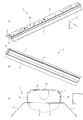
図1(a)〜(c)は、本発明の第1実施形態に係るLED照明装置1の構成例を示す図である。詳しくは、図1(a)はLED照明装置1を斜め上方から見た斜視図であり、図1(b)はLED照明装置1を斜め下方から見た斜視図であり、図1(c)はLED照明装置1を側方から見た側面図である。
Hereinafter, embodiments of the present invention will be described with reference to the drawings. Note that, in each drawing described below, parts having the same configuration are denoted by the same reference numerals, and repeated description thereof is omitted.
<First Embodiment>
(Constitution)
Fig.1 (a)-(c) is a figure which shows the structural example of the LED lighting apparatus 1 which concerns on 1st Embodiment of this invention. Specifically, FIG. 1A is a perspective view of the LED illumination device 1 as viewed from obliquely above, and FIG. 1B is a perspective view of the LED illumination device 1 as viewed from obliquely below. FIG. These are the side views which looked at the LED lighting apparatus 1 from the side.

図1(a)〜(c)に示すように、このLED照明装置1は、例えばトラフ型の照明装置であり、器具本体3と、第1の反射板5と、第2の反射板7と、LEDユニット9とを備える。
器具本体3は、LEDユニット9を支持すると共に、被取付部(例えば、天井、配線ダクトレール等)に取り付けられるものである。器具本体3は、LEDユニット9を支持する支持面3aの側に、LEDユニット9を収容するための凹部36を有する。また、器具本体3は、支持面3aの反対側の少なくとも一部が、被取付部に対する取付面3bとなっている。
As shown in FIGS. 1A to 1C, the LED lighting device 1 is, for example, a trough type lighting device, and includes an instrument body 3, a first reflecting plate 5, a second reflecting plate 7, and the like. The LED unit 9 is provided.
The instrument body 3 supports the LED unit 9 and is attached to a portion to be attached (for example, a ceiling, a wiring duct rail, etc.). The instrument body 3 has a recess 36 for accommodating the LED unit 9 on the side of the support surface 3 a that supports the LED unit 9. Moreover, as for the instrument main body 3, the at least one part on the opposite side of the support surface 3a becomes the attachment surface 3b with respect to a to-be-attached part.

第1の反射板5は、器具本体3の第1の側面3cに面接触した状態で取り付けられ、LEDユニット9が発光する光を予め設定した方向(例えば、床面に向かう方向)へ反射するものである。第2の反射板7は、器具本体3の第2の側面3dに面接触した状態で取り付けられ、LEDユニット9が発光する光を予め設定した方向(例えば、床面に向かう方向)へ反射するものである。第1の反射板5及び第2の反射板7と合わせて、反射笠ともいう。   The first reflecting plate 5 is attached in a state of surface contact with the first side surface 3c of the instrument body 3, and reflects light emitted from the LED unit 9 in a preset direction (for example, a direction toward the floor surface). Is. The second reflecting plate 7 is attached in a state of surface contact with the second side surface 3d of the instrument body 3, and reflects the light emitted from the LED unit 9 in a preset direction (for example, a direction toward the floor surface). Is. Together with the first reflecting plate 5 and the second reflecting plate 7, it is also called a reflective shade.

LEDユニット9は、光源がLEDであり、被取付部の反対側を光で照らすものである。このLEDユニット9は、器具本体3の凹部に着脱可能に収容される。なお、LED照明装置1を建物の天井に取り付ける場合は、図1(a)及び(c)において、Z軸のプラス方向(例えば、上方向)が天井側に相当し、Z軸のマイナス方向(例えば、下方向)が床側に相当する。以下、LED照明装置1を構成する各構成部について説明する。   In the LED unit 9, the light source is an LED, and the opposite side of the attached portion is illuminated with light. This LED unit 9 is detachably accommodated in the recess of the instrument body 3. In addition, when attaching the LED lighting apparatus 1 to the ceiling of a building, in FIG. 1 (a) and (c), the plus direction (for example, upward direction) of Z-axis corresponds to the ceiling side, and the minus direction of Z-axis ( For example, the downward direction) corresponds to the floor side. Hereinafter, each component which comprises the LED lighting apparatus 1 is demonstrated.

(1)器具本体 図2(a)〜図5(b)は、器具本体3の構成例を示す図である。詳しくは、図2(a)及び(b)は、反射笠を取り付けた状態の器具本体3を斜め上方から見た斜視図と、その一部を拡大した図である。図3(a)及び(b)は、反射笠を取り付けた状態の器具本体3を斜め下方から見た斜視図と、その一部を拡大した図である。図4(a)及び(b)は、反射笠を取り外した状態の器具本体3を斜め上方から見た斜視図と、その一部を拡大した図である。図5(a)及び(b)は、図2(a)をX2−X2’線で切断した断面図であり、図5(b)は図5(a)の一部を拡大した図である。 (1) Instrument Main Body FIGS. 2A to 5B are diagrams illustrating a configuration example of the instrument main body 3. Specifically, FIGS. 2 (a) and 2 (b) are a perspective view of the instrument body 3 with the reflective shade attached, as viewed from obliquely above, and a partially enlarged view thereof. 3 (a) and 3 (b) are a perspective view of the instrument body 3 with the reflective shade attached, as seen from obliquely below, and a partially enlarged view thereof. 4 (a) and 4 (b) are a perspective view of the instrument body 3 in a state in which the reflective shade is removed, and an enlarged view of a part thereof. 5 (a) and 5 (b) are cross-sectional views of FIG. 2 (a) taken along line X2-X2 ′, and FIG. 5 (b) is an enlarged view of a part of FIG. 5 (a). .

(1.1)支持面側の凹部
図2(a)〜図5(b)に示すように、器具本体3は、器具本体3の長手方向(例えば、Y軸方向)に沿う第1の側板31と、長手方向に沿い且つ第1の側板31と対向する第2の側板32と、長手方向の一端部に配置された第3の側板33と、長手方向の他端部に配置された第4の側板34と、第1〜第4の側板31〜34に囲まれた支持板35とを有する。そして、これら第1〜第4の側板31〜34と支持板35とによって、LEDユニットを支持する支持面3aの側に開口した凹部36を構成している。
(1.1) Recess on the Support Surface Side As shown in FIGS. 2A to 5B, the instrument body 3 is a first side plate along the longitudinal direction (for example, the Y-axis direction) of the instrument body 3. 31, a second side plate 32 that faces the first side plate 31 along the longitudinal direction, a third side plate 33 that is disposed at one end portion in the longitudinal direction, and a second side plate that is disposed at the other end portion in the longitudinal direction. 4 side plates 34 and a support plate 35 surrounded by first to fourth side plates 31 to 34. And these 1st-4th side plates 31-34 and the support plate 35 comprise the recessed part 36 opened to the side of the support surface 3a which supports an LED unit.

第1の側板31と第2の側板32は支持板35と一体となっている。例えば、金属板の長手方向に沿う両側部が金型でそれぞれ折り曲げられて、第1の側板31及び第2の側板32となっている。また、第3の側板33及び第4の側板34は、第1の側板31、第2の側板32及び支持板35とは別体に形成されている。第1の側板31、第2の側板32、第3の側板33及び第4の側板34は、器具本体3の四隅において、隣り合う側板同士が締結部品(リベット、ビス等)37で締結されている(又は、溶接されていてもよい)。   The first side plate 31 and the second side plate 32 are integrated with the support plate 35. For example, both side portions along the longitudinal direction of the metal plate are bent by a mold to form a first side plate 31 and a second side plate 32. The third side plate 33 and the fourth side plate 34 are formed separately from the first side plate 31, the second side plate 32, and the support plate 35. The first side plate 31, the second side plate 32, the third side plate 33, and the fourth side plate 34 are fastened by fastening parts (rivets, screws, etc.) 37 at the four corners of the instrument body 3. (Or may be welded).

また、器具本体3の支持板35には、ボルトを通すための貫通穴351と、天井等に配設された外部配線を凹部36の内側へ引き込むための貫通穴352と、外部配線やLEDユニット9が有する内部配線(例えば、電源用配線、調光用配線など)を凹部36の底面(即ち、支持板35の支持面3a)の側に寄せて支持するための切込み部353と、後述の固定用爪部を掛止するための貫通穴354とが設けられている。貫通穴351は1つ又は2つ以上設けられている。貫通穴352も1つ又は2つ以上設けられている。切込み部353も1つ又は2つ以上設けられている。   Further, the support plate 35 of the instrument body 3 has a through hole 351 for passing a bolt, a through hole 352 for drawing an external wiring arranged on the ceiling or the like inside the recess 36, an external wiring or an LED unit. 9 has a notch 353 for supporting the internal wiring (for example, power supply wiring, dimming wiring, etc.) that is located near the bottom surface of the recess 36 (that is, the support surface 3a of the support plate 35), A through hole 354 for hooking the fixing claw portion is provided. One or two or more through holes 351 are provided. One or more through holes 352 are also provided. One or more incisions 353 are also provided.

例えば、LED照明装置1を建物の天井に取り付ける場合は、天井から床面に向かって突き出た長ボルトが用意されている。この長ボルトを器具本体3の貫通穴351に通し、ナットで固定することにより、器具本体3を天井に固定する。また、切込み部353を凹部36の内側に折り曲げて、切込み部353と凹部36の底面との間に配線を挟むことによって、上記の配線等を凹部36の底面の側に寄せて支持する。   For example, when the LED lighting device 1 is attached to the ceiling of a building, a long bolt protruding from the ceiling toward the floor surface is prepared. By passing this long bolt through the through hole 351 of the instrument body 3 and fixing with a nut, the instrument body 3 is fixed to the ceiling. Further, the cut portion 353 is bent inside the concave portion 36 and the wiring is sandwiched between the cut portion 353 and the bottom surface of the concave portion 36, thereby supporting the above-described wiring and the like toward the bottom surface side of the concave portion 36.

(1.2)取付面側の凸部
また、図3(a)及び(b)に示すように、器具本体3は、LEDユニット9を支持面3aの側に取り付けるためのバネ金具37と、凸部41とを有する。バネ金具37は凹部36の底面に設けられている。凸部41は、凹部36の底面の反対側の面(即ち、取付面3b)に設けられている。また、バネ金具37は、バネ371と、バネ371を支持するバネ支持部372と、バネ371の弾性力によって支持面3a側へ押圧されるアーム部373とを有する。バネ支持部372は、締結部材(例えば、リベット、ビス等)375と、固定用爪部376とによって、凹部36の底面に固定されている。
(1.2) Convex portion on the mounting surface side As shown in FIGS. 3A and 3B, the appliance body 3 includes a spring metal fitting 37 for mounting the LED unit 9 on the support surface 3a side, And a convex portion 41. The spring fitting 37 is provided on the bottom surface of the recess 36. The convex portion 41 is provided on the surface opposite to the bottom surface of the concave portion 36 (that is, the mounting surface 3b). The spring metal fitting 37 includes a spring 371, a spring support portion 372 that supports the spring 371, and an arm portion 373 that is pressed toward the support surface 3 a by the elastic force of the spring 371. The spring support portion 372 is fixed to the bottom surface of the recess 36 by a fastening member (for example, a rivet, a screw, etc.) 375 and a fixing claw portion 376.

図2(a)〜図4(b)に示すように、締結部材375は、器具本体3の取付面3bの側からバネ支持部372を固定している。また、固定用爪部376は、その一部(即ち、掛止片)が支持板35に設けられた貫通穴354の縁部に掛止されている。このため、締結部材375の頭部及び固定用爪部376の掛止片は器具本体3の取付面3bから上方へ突き出ている。LED照明装置1を被取付部に取り付けると、この締結部材375の頭部と固定用爪部376の掛止片とが被取付部に接触する。   As shown in FIGS. 2A to 4B, the fastening member 375 fixes the spring support portion 372 from the attachment surface 3 b side of the instrument body 3. A part of the fixing claw portion 376 (that is, a hooking piece) is hooked on an edge portion of the through hole 354 provided in the support plate 35. Therefore, the head of the fastening member 375 and the latching piece of the fixing claw 376 protrude upward from the attachment surface 3 b of the instrument body 3. When the LED lighting device 1 is attached to the attachment portion, the head of the fastening member 375 and the latching piece of the fixing claw portion 376 come into contact with the attachment portion.

ここで、LED照明装置1のうち被取付部に接触する部分が、締結部材375の頭部と固定用爪部376の掛止片のみでは配置のバランスが悪く、LED照明装置1の被取付部に対する取付状態が安定しない可能性がある。そこで、器具本体3の取付面3bに、1つ又は2つ以上の凸部41が設けられている。この凸部41は例えば樹脂からなる。また、この凸部41の取付面3bからの高さは、締結部材375の頭部の取付面3bからの高さや、固定用爪部376の掛止片の取付面3bからの高さと同じ、又は、(押圧されると弾性で凹む樹脂の物性を考慮して)若干高めに設定されている。これにより、LED照明装置1のうち被取付部に接触する部分の数を増やし、配置のバランスを取ることができるので、LED照明装置1の被取付部に対する取付状態の安定化に寄与することができる。   Here, the portion of the LED lighting device 1 that comes into contact with the mounted portion has a poor balance in arrangement only with the head of the fastening member 375 and the hooking piece of the fixing claw portion 376, and the mounted portion of the LED lighting device 1 The mounting state may not be stable. Therefore, one or two or more convex portions 41 are provided on the attachment surface 3b of the instrument body 3. This convex part 41 consists of resin, for example. Further, the height of the convex portion 41 from the mounting surface 3b is the same as the height from the mounting surface 3b of the head of the fastening member 375 and the height from the mounting surface 3b of the latching piece of the fixing claw portion 376. Alternatively, it is set slightly higher (in consideration of the physical properties of the resin that is dented elastically when pressed). Thereby, since the number of the parts which contact a to-be-attached part among LED lighting apparatuses 1 can be increased and arrangement | positioning balance can be taken, it can contribute to stabilization of the attachment state with respect to the to-be-attached part of LED lighting apparatus 1. it can.

なお、締結部材375の頭部と固定用爪部376の掛止片は、次に説明するコネクタ端子の位置決め用の凸部、締結部材の脚部、アース端子よりも大きく、被取付部との接触面積が大きい。また、凸部41は樹脂からなり弾性を有する。このため、締結部材375の頭部、固定用爪部376の掛止片、凸部41が被取付部に接触しても、被取付部を傷つけることを防ぐことができる。   Note that the fastening pieces of the fastening member 375 head and the fixing claw 376 are larger than the connector terminal positioning projection, the fastening member leg, and the ground terminal, which will be described below, and Large contact area. The convex portion 41 is made of resin and has elasticity. For this reason, even if the head part of the fastening member 375, the latching piece of the fixing claw part 376, and the convex part 41 contact the attached part, it is possible to prevent the attached part from being damaged.

(1.3)取付面側の凹部
また、器具本体3は、LEDユニット9の内部配線と外部配線とを電気的に接続するためのコネクタ端子と、コネクタ端子を設置するための端子台とを有する。コネクタ端子及び端子台は、凹部36の底面に設けられている。
例えば、図3(a)及び(b)に示すように、コネクタ端子として、LEDユニット9の電源用配線と外部配線とを電気的に接続する電源用コネクタ端子42と、LEDユニット9の調光用配線と外部配線とを電気的に接続する調光用コネクタ端子44とがある。また、端子台として、電源用コネクタ端子42を設置するための電源用端子台43と、調光用コネクタ端子を設置するための調光用端子台とがある。
(1.3) Recess on the mounting surface side In addition, the appliance body 3 includes a connector terminal for electrically connecting the internal wiring and the external wiring of the LED unit 9 and a terminal block for installing the connector terminal. Have. The connector terminal and the terminal block are provided on the bottom surface of the recess 36.
For example, as shown in FIGS. 3A and 3B, as connector terminals, a power connector terminal 42 that electrically connects the power supply wiring of the LED unit 9 and the external wiring, and the light control of the LED unit 9. And a dimming connector terminal 44 for electrically connecting the external wiring and the external wiring. Further, as the terminal block, there are a power supply terminal block 43 for installing the power connector terminal 42 and a dimming terminal block for installing the dimming connector terminal.

図6は、電源用コネクタ端子42、電源用端子台43とその周辺部の構成例を示す断面図である。図6に示すように、電源用コネクタ端子42のうち電源用端子台43と対向する面側には、位置決め用の凸部421と、締結部材(例えば、リベット、ビス等)45を通すための貫通穴422と、アース端子423とが設けられている。また、電源用端子台43には、位置決め用の凸部421を通すための貫通穴431と、締結部材45を通すため貫通穴432と、アース端子423を通すための貫通穴433とが設けられている。   FIG. 6 is a cross-sectional view illustrating a configuration example of the power connector terminal 42, the power terminal block 43, and the peripheral portion thereof. As shown in FIG. 6, a positioning convex portion 421 and a fastening member (for example, a rivet, a screw, etc.) 45 are passed through the surface of the power connector terminal 42 facing the power terminal block 43. A through hole 422 and a ground terminal 423 are provided. Further, the power terminal block 43 is provided with a through hole 431 through which the positioning convex portion 421 passes, a through hole 432 through which the fastening member 45 passes, and a through hole 433 through which the ground terminal 423 passes. ing.

位置決め用の凸部421が貫通穴431に差し込まれることによって、電源用端子台43に対する電源用コネクタ端子42の位置が決められる。また、この位置決めによって、貫通穴422、432が上下方向で連通する(即ち、接続する)と共に、アース端子423が貫通穴433に差し込まれる。そして、例えば電源用コネクタ端子42の側から、貫通穴422、432に1本の締結部材45を通すことによって、電源用コネクタ端子42が電源用端子台43に固定される。   The position of the power connector terminal 42 relative to the power terminal block 43 is determined by inserting the positioning convex portion 421 into the through hole 431. Further, by this positioning, the through holes 422 and 432 are communicated (that is, connected) in the vertical direction, and the ground terminal 423 is inserted into the through hole 433. For example, the power connector terminal 42 is fixed to the power terminal block 43 by passing one fastening member 45 through the through holes 422 and 432 from the power connector terminal 42 side.

また、電源用端子台43の反対側は、その周囲の取付面3bに対して凹んでおり、凹部47となっている。この凹部47の取付面に対する深さをDとする。また、位置決め用の凸部421、締結部材45の脚部、アース端子423は、電源用端子台43の反対側へ突き出ている。これら各部の突出長さの最大値をLとする。ここで、DはL1よりも大きな値(D>L1)となるように設定されているので、位置決め用の凸部421、締結部材45の脚部、アース端子423が被取付部に接触することを防ぐことができる。位置決め用の凸部421、締結部材45の脚部、アース端子423の取付面側に突き出た部分が尖っている場合でも、これらは被取付部に接触しないので、被取付部を傷つけてしまうことを防ぐことができる。
なお、調光用コネクタ端子44(図3参照)及び調光用端子台の構成も、図6に示した電源用コネクタ端子42及び電源用端子台43の構成と同様である。これにより、調光用コネクタ端子44が有する位置決め用の凸部、アース端子、調光用コネクタ端子44を調光用端子台に固定する締結部材の脚部が、被取付部に接触することを防ぐことができる。
Further, the opposite side of the power terminal block 43 is recessed with respect to the surrounding mounting surface 3 b, thereby forming a recess 47. The depth of the recess 47 with respect to the mounting surface is D. Further, the positioning convex portion 421, the leg portion of the fastening member 45, and the ground terminal 423 protrude to the opposite side of the power supply terminal block 43. Let L be the maximum value of the protruding length of each of these parts. Here, since D is set to be a value larger than L1 (D> L1), the positioning convex portion 421, the leg portion of the fastening member 45, and the ground terminal 423 are in contact with the attached portion. Can be prevented. Even if the protruding portion 421 for positioning, the leg portion of the fastening member 45, and the portion protruding to the mounting surface side of the ground terminal 423 are sharp, they do not contact the mounted portion, and thus the mounted portion is damaged. Can be prevented.
The configurations of the dimming connector terminal 44 (see FIG. 3) and the dimming terminal block are the same as the configurations of the power connector terminal 42 and the power terminal block 43 shown in FIG. Accordingly, the positioning convex portion, the grounding terminal, and the leg portion of the fastening member that fixes the dimming connector terminal 44 to the dimming terminal block come into contact with the mounted portion. Can be prevented.

(1.4)段差部
また、器具本体3の長手方向に沿う側面のうち取付面(例えば、上面)の側には、器具本体3の長手方向に沿って段差部が設けられている。例えば図5(a)及び(b)に示すように、器具本体3の第1の側面3c(即ち、第1の側板31の外側の側面)であって、取付面3bの側には、器具本体3の長手方向に沿って第1の段差部311が設けられている。第1の段差部311の断面視による形状(即ち、断面形状)はL字の形状である。L字の形状とは、第1の線分と第2の線分とが直交する形状のことである。同様に、器具本体3の第2の側面3d(即ち、第2の側板32の外側の側面)であって、取付面3bの側には、器具本体3の長手方向に沿って第2の段差部321が設けられている。第2の段差部321の断面形状も、L字の形状である。
(1.4) Stepped portion Further, a stepped portion is provided along the longitudinal direction of the instrument body 3 on the side of the mounting surface (for example, the upper surface) among the side surfaces along the longitudinal direction of the instrument body 3. For example, as shown in FIGS. 5 (a) and 5 (b), the first side surface 3c of the instrument main body 3 (that is, the outer side surface of the first side plate 31) is provided on the side of the mounting surface 3b. A first step portion 311 is provided along the longitudinal direction of the main body 3. The shape (that is, the cross-sectional shape) of the first step portion 311 in a cross-sectional view is an L shape. The L-shaped shape is a shape in which the first line segment and the second line segment are orthogonal to each other. Similarly, on the second side surface 3d of the instrument body 3 (that is, the outer side surface of the second side plate 32) on the attachment surface 3b side, a second step along the longitudinal direction of the instrument body 3 is provided. A part 321 is provided. The cross-sectional shape of the second step portion 321 is also an L shape.

第1の段差部311には、凹部36の内側へ貫通する貫通穴312が設けられている。同様に、第2の段差部321には、凹部36の内側へ貫通する貫通穴322が設けられている。また、第1の側板31には締結部材を通すための貫通穴313が設けられている。同様に、第2の側板32には締結部材を通すための貫通穴323が設けられている。   The first step portion 311 is provided with a through hole 312 that penetrates to the inside of the recess 36. Similarly, the second stepped portion 321 is provided with a through hole 322 that penetrates to the inside of the recess 36. Further, the first side plate 31 is provided with a through hole 313 for passing a fastening member. Similarly, the second side plate 32 is provided with a through hole 323 for passing a fastening member.

(2)反射板
(2.1)第1の反射板
図7(a)及び(b)は、第1の反射板5の構成例を示す図である。詳しくは、図7(a)は第1の反射板5を斜め上方から見た斜視図であり、図7(b)はその一部を拡大した図である。
(2) Reflector (2.1) First Reflector FIGS. 7A and 7B are diagrams showing a configuration example of the first reflector 5. Specifically, FIG. 7A is a perspective view of the first reflecting plate 5 as viewed obliquely from above, and FIG. 7B is a partially enlarged view thereof.

図7(a)及び(b)に示すように、第1の反射板5は、器具本体3の第1の側面3cに面接触で取り付けるための取付部51と、LEDユニット9が発光する光を反射するための反射部52と、取付部51と反射部52とを接続する接続部53と、を有する。取付部51は接続部53の一方の側に位置し、反射部52は接続部53の他方の側に位置する。また、取付部51の側部には、この側部から外側へ突き出た突片54が設けられている。   As shown in FIGS. 7 (a) and 7 (b), the first reflecting plate 5 includes a mounting portion 51 for mounting on the first side surface 3c of the instrument body 3 by surface contact, and light emitted from the LED unit 9. And a connecting portion 53 that connects the attachment portion 51 and the reflecting portion 52. The attachment portion 51 is located on one side of the connection portion 53, and the reflection portion 52 is located on the other side of the connection portion 53. In addition, a protruding piece 54 protruding outward from the side portion is provided on the side portion of the attachment portion 51.

また、図5(a)及び(b)に示すように、取付部51と接続部53及び反射部52は一体となっており、取付部51に対して接続部53が屈曲して連なると共に、接続部53に対して反射部52が屈曲して連なっている。例えば、取付部51と接続部53とが成す角度θ1は90°である。また、接続部53と反射部52とが成す角度θ2は100°以上、170°以下である。さらに、取付部51の長手方向に沿う側部は、この側部が器具本体3の第1の段差部311に掛かるように、断面視でL字の形状となっている。また、取付部51には、締結部材を通すための貫通穴55が設けられている。   Further, as shown in FIGS. 5A and 5B, the attachment portion 51, the connection portion 53, and the reflection portion 52 are integrated, and the connection portion 53 is bent and connected to the attachment portion 51. The reflection part 52 is bent and connected to the connection part 53. For example, the angle θ1 formed by the attachment portion 51 and the connection portion 53 is 90 °. Further, the angle θ2 formed by the connecting portion 53 and the reflecting portion 52 is not less than 100 ° and not more than 170 °. Further, the side portion along the longitudinal direction of the attachment portion 51 has an L shape in a cross-sectional view so that the side portion is hooked on the first step portion 311 of the instrument body 3. Further, the attachment portion 51 is provided with a through hole 55 for passing a fastening member.

(2.2)第2の反射板
第2の反射板7も第1の反射板5と同様の構成を有する。即ち、図5(a)及び(b)に示すように、第2の反射板7は、取付部71と接続部73及び反射部72を有する。また、取付部71の側部には、この側部から外側へ突き出た突片74が設けられている。取付部71と接続部73及び反射部72は一体となっており、取付部71に対して接続部73が屈曲して連なると共に、接続部73に対して反射部72が屈曲して連なっている。また、取付部71の長手方向に沿う側部は、この側部が器具本体3の第1の段差部311に掛かるように、断面視でL字の形状となっている。さらに、取付部71には、締結部材を通すための貫通穴75が設けられている。
(2.2) Second Reflector The second reflector 7 has the same configuration as the first reflector 5. That is, as shown in FIGS. 5A and 5B, the second reflecting plate 7 has a mounting portion 71, a connecting portion 73, and a reflecting portion 72. Further, a protruding piece 74 protruding outward from the side portion is provided on the side portion of the attachment portion 71. The attachment portion 71, the connection portion 73, and the reflection portion 72 are integrated, and the connection portion 73 is bent and connected to the attachment portion 71, and the reflection portion 72 is bent and connected to the connection portion 73. . Further, the side portion along the longitudinal direction of the attachment portion 71 has an L shape in a cross-sectional view so that the side portion is hooked on the first step portion 311 of the instrument body 3. Further, the attachment portion 71 is provided with a through hole 75 for passing a fastening member.

(2.3)反射板の固定方法
器具本体3に対する第1の反射板5の固定方法は次の通りである。まず、第1の反射板5の取付部51の側部を器具本体3の第1の段差部311に掛けて、取付部51を器具本体3の第1の側面3cに面接触させると共に、突片54を貫通穴312に差し込む。これにより、器具本体3の第1の側面3cに対して第1の反射板5が位置決めされ、第1の反射板5の貫通穴55と、器具本体3の貫通穴313とが左右方向で連通する。次に、例えば第1の反射板5の側から、貫通穴55、313に締結部材57を通し、この締結部材57で第1の反射板5を器具本体3の第1の側面3cに固定する。この締結部材57により、第1の反射板5は第1の側面3cに相対的に押圧され、第1の側面3cに面接触した状態で固定される。
(2.3) Fixing method of reflecting plate The fixing method of the 1st reflecting plate 5 with respect to the instrument main body 3 is as follows. First, the side portion of the attachment portion 51 of the first reflecting plate 5 is hung on the first step portion 311 of the instrument main body 3 to bring the attachment portion 51 into surface contact with the first side surface 3c of the instrument main body 3. The piece 54 is inserted into the through hole 312. Thereby, the 1st reflecting plate 5 is positioned with respect to the 1st side surface 3c of the instrument main body 3, and the through-hole 55 of the 1st reflective plate 5 and the through-hole 313 of the instrument main body 3 are connected in the left-right direction. To do. Next, for example, the fastening member 57 is passed through the through holes 55 and 313 from the side of the first reflecting plate 5, and the first reflecting plate 5 is fixed to the first side surface 3 c of the instrument body 3 with the fastening member 57. . By this fastening member 57, the 1st reflecting plate 5 is relatively pressed by the 1st side surface 3c, and is fixed in the state which surface-contacted to the 1st side surface 3c.

なお、器具本体3の貫通穴312に差し込んだ突片54の先端部は、図5(a)の矢印で示すように、貫通穴312の軸方向と交差する方向(例えば、下方向)に曲げておくことが好ましい。これにより、突片54を貫通穴312の縁部に掛止することができ、突片54と締結部材57の2か所で第1の反射板5を器具本体3に固定することができる。
器具本体3に対する第2の反射板7の固定方法も、第1の反射板5の場合と同様である。即ち、第2の反射板7の取付部71の側部を器具本体3の第2の段差部321に掛けて、取付部71を器具本体3の第2の側面3dに面接触させると共に、突片74を貫通穴322に差し込む。これにより、器具本体3の第2の側面3dに対して第2の反射板7が位置決めされ、第2の反射板7の貫通穴75と、器具本体3の貫通穴323とが左右方向で連通する。次に、例えば第2の反射板7の側から、貫通穴75、323に締結部材77を通し、この締結部材77で第2の反射板7を器具本体3の第2の側面3dに固定する。この締結部材57により、第2の反射板7は第1の側面3cに相対的に押圧され、第1の側面3cに面接触した状態で固定される。
Note that the tip of the protruding piece 54 inserted into the through hole 312 of the instrument body 3 is bent in a direction (for example, downward) intersecting the axial direction of the through hole 312 as indicated by an arrow in FIG. It is preferable to keep it. As a result, the projecting piece 54 can be hooked to the edge of the through hole 312, and the first reflector 5 can be fixed to the instrument body 3 at the two locations of the projecting piece 54 and the fastening member 57.
The method of fixing the second reflecting plate 7 to the instrument body 3 is also the same as that of the first reflecting plate 5. That is, the side portion of the mounting portion 71 of the second reflecting plate 7 is hung on the second stepped portion 321 of the instrument body 3 to bring the mounting portion 71 into surface contact with the second side surface 3d of the instrument body 3 and The piece 74 is inserted into the through hole 322. Thereby, the 2nd reflecting plate 7 is positioned with respect to 2nd side 3d of the instrument main body 3, and the through-hole 75 of the 2nd reflective plate 7 and the through-hole 323 of the instrument main body 3 are connected in the left-right direction. To do. Next, for example, the fastening member 77 is passed through the through holes 75 and 323 from the second reflecting plate 7 side, and the second reflecting plate 7 is fixed to the second side surface 3d of the instrument main body 3 by the fastening member 77. . By this fastening member 57, the second reflecting plate 7 is relatively pressed against the first side surface 3c and fixed in a state of surface contact with the first side surface 3c.

なお、器具本体3の貫通穴322に通された突片74の先端部は、図5(a)の矢印で示すように、貫通穴322の軸方向と交差する方向(例えば、下方向)に曲げておくことが好ましい。これにより、突片74を貫通穴32の縁部に掛止することができ、突片74と締結部材77の2か所で第2の反射板7を器具本体3に固定することができる。   Note that the tip of the protruding piece 74 passed through the through hole 322 of the instrument body 3 is in a direction (for example, downward) intersecting the axial direction of the through hole 322 as shown by the arrow in FIG. It is preferable to bend. Thereby, the projecting piece 74 can be hooked on the edge of the through hole 32, and the second reflecting plate 7 can be fixed to the instrument body 3 at two locations of the projecting piece 74 and the fastening member 77.

(2.4)締結部材による反射板の固定位置
ところで、締結部材57による第1の反射板5の固定位置は、第1の反射板5と器具本体3の第1の側面3cとが面接触する領域R1のうち、取付面3bに近い第1の縁部R1aと取付面3bから遠い第2の縁部R1bとの間の中心部よりも第2の縁部R1bに近い位置(即ち、凹部36の開口端面36bに近い位置)R1cとなっている。これにより、特に開口端面36bの側において、第1の反射板5と器具本体3とを密着させて隙間が生じないようにすることができ、第1の反射板5と器具本体3との間に、隙間に起因する影を生じさせないようにすることができる。
(2.4) Fixing position of reflecting plate by fastening member By the way, the fixing position of the first reflecting plate 5 by the fastening member 57 is such that the first reflecting plate 5 and the first side surface 3c of the instrument body 3 are in surface contact. In the region R1, the position closer to the second edge R1b than the center between the first edge R1a close to the attachment surface 3b and the second edge R1b far from the attachment surface 3b (that is, the recess) 36, the position close to the open end face 36b) R1c. Thereby, especially in the opening end surface 36b side, the 1st reflecting plate 5 and the instrument main body 3 can be closely_contact | adhered, and it can be made not to produce a clearance gap between the 1st reflecting plate 5 and the instrument main body 3. FIG. Further, it is possible to prevent a shadow caused by the gap from being generated.

また、締結部材77による第2の反射板7の固定位置も、第1の反射板5の場合と同様である。即ち、締結部材77による第2の反射板7の固定位置は、第2の反射板7と器具本体の第2の側面3dとが面接触する領域R2のうち、取付面3bに近い第1の縁部R2aと取付面3bから遠い第2の縁部R2bとの間の中心部よりも第2の縁部R2bに近い位置(即ち、凹部36の開口端面36bに近い位置)R2cとなっている。これにより、特に開口端面36bの側において、第2の反射板7と器具本体3とを密着させて隙間が生じないようにすることができ、第2の反射板7と器具本体3との間に、隙間に起因する影を生じさせないようにすることができる。   Further, the fixing position of the second reflecting plate 7 by the fastening member 77 is the same as that of the first reflecting plate 5. That is, the fixing position of the second reflecting plate 7 by the fastening member 77 is the first position close to the mounting surface 3b in the region R2 where the second reflecting plate 7 and the second side surface 3d of the instrument body are in surface contact. R2c is a position closer to the second edge R2b than the center between the edge R2a and the second edge R2b far from the mounting surface 3b (ie, a position closer to the opening end face 36b of the recess 36). . Thereby, especially on the opening end surface 36b side, the second reflector 7 and the instrument body 3 can be brought into close contact with each other so that no gap is generated. Further, it is possible to prevent a shadow caused by the gap from being generated.

また、図5(b)に示すように、凹部36の開口端面36bの側で、器具本体3と第1の反射板5との接触部6は同一平面内にある(即ち、面一である。)。同様に、凹部36の開口端面36bの側で、器具本体3と第2の反射板7との接触部も同一平面内にある。これにより、上記の各接触部に段差がある場合と比較して、段差に起因する影を生じさせないようにすることができる。   Further, as shown in FIG. 5B, on the side of the opening end surface 36b of the recess 36, the contact portion 6 between the instrument main body 3 and the first reflecting plate 5 is in the same plane (that is, flush). .) Similarly, on the side of the opening end surface 36b of the recess 36, the contact portion between the instrument body 3 and the second reflecting plate 7 is also in the same plane. Thereby, compared with the case where there is a level difference in each of the contact parts, it is possible to prevent a shadow due to the level difference from being generated.

また、図5(b)に示すように、接触部6を挟んで同一平面内にある第1の反射板5と第1の側板31の合計長さL2は、例えば、0.5cm以上、7.5cm以下である。図示しないが、接触部を挟んで同一平面内にある第2の反射板7と第2の側板32の合計長さも、上記Lと同じである。これにより、器具本体3に対してLEDユニット9を着脱する際に、LEDユニット9と第1の反射板5との間に作業者の指等を配置することができる。LEDユニット9の着脱が容易となる。   Further, as shown in FIG. 5B, the total length L2 of the first reflecting plate 5 and the first side plate 31 in the same plane with the contact portion 6 interposed therebetween is, for example, 0.5 cm or more, 7 .5 cm or less. Although not shown, the total length of the second reflector 7 and the second side plate 32 in the same plane with the contact portion in between is also the same as L described above. Thereby, when attaching and detaching the LED unit 9 with respect to the instrument main body 3, an operator's finger | toe etc. can be arrange | positioned between the LED unit 9 and the 1st reflecting plate 5. FIG. The LED unit 9 can be easily attached and detached.

また、第1の側板31のうち開口端面36b側の端部31aは、角が隠れるように曲げられている。同様に、第2の側板32のうち開口端面36b側の端部32aも、角が隠れるように曲げられている。これにより、LEDユニット9を着脱する際に、作業者の指が器具本体3の角に接触する可能性を低減することができる。   Moreover, the edge part 31a by the side of the opening end surface 36b among the 1st side plates 31 is bent so that a corner may be hidden. Similarly, the end portion 32a on the opening end face 36b side of the second side plate 32 is also bent so that the corners are hidden. Thereby, when attaching and detaching the LED unit 9, it is possible to reduce the possibility that the operator's finger contacts the corner of the instrument body 3.

(3)LEDユニット
図8(a)及び(b)は、LEDユニット9の構成例を示す図である。詳しくは、図8(a)はLEDユニット9の主面側を斜め上方から見た斜視図であり、図5(b)はLEDユニット9の背面側を斜め上方から見た斜視図である。
また、図9(a)及び(b)は、LED基板93の構成例を示す図である。詳しくは、図9(a)はLED基板93を斜め上方から見た斜視図であり、図9(b)はその一部を拡大した図である。
(3) LED Unit FIGS. 8A and 8B are diagrams showing a configuration example of the LED unit 9. Specifically, FIG. 8A is a perspective view of the main surface side of the LED unit 9 as viewed obliquely from above, and FIG. 5B is a perspective view of the back side of the LED unit 9 as viewed from obliquely upward.
9A and 9B are diagrams showing a configuration example of the LED substrate 93. FIG. Specifically, FIG. 9A is a perspective view of the LED substrate 93 viewed obliquely from above, and FIG. 9B is an enlarged view of a part thereof.

図8(a)〜図9(b)に示すように、LEDユニット9は、ヒートシンク91と、ヒートシンク91の背面側に設けられた電源ボックス92と、ヒートシンク91の主面側に配置されたLED基板93と、ヒートシンク91の主面側に設けられてLED基板93を部分的に覆う反射シート94と、ヒートシンク91の主面側に設けられてLED基板93及び反射シート94を覆うカバーパネル95と、ヒートシンク91の長手方向の両端部を覆うサイドカバー96とを有する。   As shown in FIGS. 8A to 9B, the LED unit 9 includes a heat sink 91, a power supply box 92 provided on the back side of the heat sink 91, and LEDs arranged on the main surface side of the heat sink 91. A substrate 93, a reflection sheet 94 provided on the main surface side of the heat sink 91 and partially covering the LED substrate 93, and a cover panel 95 provided on the main surface side of the heat sink 91 and covering the LED substrate 93 and the reflection sheet 94; And a side cover 96 that covers both ends of the heat sink 91 in the longitudinal direction.

(3.1)ヒートシンク
図8(a)〜図9(b)に示すように、ヒートシンク91は、LED基板93や電源ボックス92等が取り付けられる支持板911と、第1の側板912と、第2の側板912と、を有する。支持板911は、主面と背面とを有し、平面視による形状(以下、平面形状)は一方向に細長い矩形状である。また、第1の側板912は、支持板911の長手方向に沿う両側部の一方に設けられ、支持板911の背面側で起立している。第2の側板913は、支持板911の長手方向に沿う両側部の他方に設けられ、支持板911の背面側で起立している。第1の側板912と第2の側板913は互いに対向している。また、第1の側板912と第2の側板913は支持板911と一体化している。例えば、金属板の長手方向に沿う両側部がそれぞれ折り曲げられて、第1の側板912及び第2の側板913となっている。
(3.1) Heat Sink As shown in FIGS. 8A to 9B, the heat sink 91 includes a support plate 911 to which the LED board 93 and the power supply box 92 are attached, a first side plate 912, 2 side plates 912. The support plate 911 has a main surface and a back surface, and a shape in plan view (hereinafter referred to as a planar shape) is a rectangular shape elongated in one direction. The first side plate 912 is provided on one of both side portions along the longitudinal direction of the support plate 911 and stands on the back side of the support plate 911. The second side plate 913 is provided on the other side of the both sides along the longitudinal direction of the support plate 911 and stands on the back side of the support plate 911. The first side plate 912 and the second side plate 913 are opposed to each other. Further, the first side plate 912 and the second side plate 913 are integrated with the support plate 911. For example, both side portions along the longitudinal direction of the metal plate are bent to form a first side plate 912 and a second side plate 913.

(3.2)電源ボックス
図8(b)に示すように、電源ボックス92は、その内部にLED点灯回路(即ち、電源回路)を収納する筐体である。電源ボックス92は、プラスチック、アルミニウム又はステンレス等の材料からなり、その外観形状は一方向に長く延びた形状(即ち、長手方向を有する形状)である。LED点灯回路は、例えば、配線ダクトレールから供給される交流電力を直流に変換し、その出力(即ち、直流電力)をLED基板93に供給する。電源ボックス92は、図示しない締結部材(例えば、リベット、ビス等)によって、ヒートシンク91の背面側に固定されている。
(3.2) Power Supply Box As shown in FIG. 8B, the power supply box 92 is a housing that houses an LED lighting circuit (that is, a power supply circuit) therein. The power supply box 92 is made of a material such as plastic, aluminum, or stainless steel, and has an external shape that extends long in one direction (that is, a shape having a longitudinal direction). For example, the LED lighting circuit converts AC power supplied from a wiring duct rail into DC and supplies the output (that is, DC power) to the LED board 93. The power supply box 92 is fixed to the back side of the heat sink 91 by fastening members (not shown) (for example, rivets, screws, etc.).

(3.3)LED基板
図9(a)及び(b)に示すように、LED基板93の平面形状は一方向に細長い矩形状である。LED基板93は、複数のLED素子931と、複数のLED素子931間を接続する導電層(図示せず)と、導電層を覆って保護する保護層(図示せず)と、導電層に接続するコネクタ端子933と、を有する。
(3.3) LED substrate As shown in FIGS. 9A and 9B, the planar shape of the LED substrate 93 is a rectangular shape elongated in one direction. The LED substrate 93 is connected to the plurality of LED elements 931, a conductive layer (not shown) connecting the plurality of LED elements 931, a protective layer (not shown) covering and protecting the conductive layer, and the conductive layer. Connector terminal 933.

LED素子931は、例えば半導体を用いたpn接合を有し、pn接合の順方向にバイアスが加えられて電流が流れると、電子と正孔とが再結合して光を放出する素子である。LED素子931が発光する色は特に制限されず、例えば昼白色でもよいし、電球色でもよい。
導電層は、LED基板93の基材上に形成されている。例えば、基材はFR−4又はCEM−3であり、導電層は銅(Cu)からなる。導電層にLED素子931が取り付けられることにより、複数のLED素子931間が接続される。保護層は絶縁性であり、その色は反射シート94と同じ色(例えば、白色)であることが好ましい。コネクタ端子933は、例えば、LED基板93へ電流を入力するための入力用端子と、LED基板93から電流を出力するための出力用端子とを有する。LED基板93は、締結部材(例えば、リベット、ビス等)98によって、ヒートシンク91に固定されている。
The LED element 931 is an element that has a pn junction using, for example, a semiconductor and emits light when electrons and holes are recombined when a current flows with a bias applied in the forward direction of the pn junction. The color emitted by the LED element 931 is not particularly limited, and may be, for example, daylight white or a light bulb color.
The conductive layer is formed on the base material of the LED substrate 93. For example, the base material is FR-4 or CEM-3, and the conductive layer is made of copper (Cu). By attaching the LED elements 931 to the conductive layer, the plurality of LED elements 931 are connected. The protective layer is insulative, and the color thereof is preferably the same color as the reflective sheet 94 (for example, white). The connector terminal 933 includes, for example, an input terminal for inputting current to the LED board 93 and an output terminal for outputting current from the LED board 93. The LED substrate 93 is fixed to the heat sink 91 by fastening members (for example, rivets, screws, etc.) 98.

なお、図9(a)及び(b)では、LEDユニット9が2枚のLED基板93を有し、これら2枚のLED基板93はその長手方向に向かって一列に並んで配置されている場合を示している。しかしながら、本発明はこれに限定されるものではない。本発明では、LEDユニット9が有するLED基板93の枚数に制限はない。例えば、LEDユニット9が有するLED基板93は1枚でも良いし、3枚以上でもよい。LED基板93が3枚以上の場合は、例えば、3枚以上のLED基板93がその長手方向に向かって一列に並んで配置される。   9A and 9B, the LED unit 9 has two LED boards 93, and these two LED boards 93 are arranged in a line in the longitudinal direction. Is shown. However, the present invention is not limited to this. In the present invention, the number of LED substrates 93 included in the LED unit 9 is not limited. For example, the LED unit 93 included in the LED unit 9 may be one or three or more. When there are three or more LED substrates 93, for example, three or more LED substrates 93 are arranged in a line in the longitudinal direction.

また、LED基板93は、電源オフ時の放電電流によりLED素子931が発光することを抑制するために、1つ又は2つ以上の抵抗素子(図示せず)を有していてもよい。この場合、LED素子931と抵抗素子との間も導電層で接続される。電源オフ時の放電電流を、LED素子931だけでなく抵抗素子にも流すことにより、LED素子931に流れる電流量を低減し、電源オフ時の発光を抑制することができる。   Further, the LED substrate 93 may have one or two or more resistance elements (not shown) in order to suppress the LED element 931 from emitting light due to a discharge current when the power is turned off. In this case, the LED element 931 and the resistance element are also connected by the conductive layer. By causing the discharge current when the power is off to flow not only to the LED element 931 but also to the resistance element, the amount of current flowing through the LED element 931 can be reduced, and light emission when the power is off can be suppressed.

(3.4)反射シート
図9(a)及び(b)に示すように、反射シート94は、LED基板93のうちLED素子931以外を覆うように配置されている。例えば、LEDユニット9は4枚の反射シート94を有する。4枚の反射シート94はそれぞれ、LED基板93の長手方向に沿う側部からヒートシンク91の長手方向に沿う側部にかけて配置されている。
反射シート94の材質は、例えばポリエチレンテレフタラート(PET)又はポリプロピレン(PP)である。また、反射シート94の表面は、例えば白色であり、光沢を有する。なお、反射シート94の材質、表面の色及び光沢の有無に特に制限はないが、光の反射率が高いものを用いることによって、LED照明装置1の光束を高めることができる。
(3.4) Reflective Sheet As shown in FIGS. 9A and 9B, the reflective sheet 94 is disposed so as to cover the LED substrate 93 other than the LED element 931. For example, the LED unit 9 has four reflection sheets 94. Each of the four reflection sheets 94 is arranged from a side portion along the longitudinal direction of the LED substrate 93 to a side portion along the longitudinal direction of the heat sink 91.
The material of the reflection sheet 94 is, for example, polyethylene terephthalate (PET) or polypropylene (PP). Further, the surface of the reflection sheet 94 is, for example, white and glossy. In addition, although there is no restriction | limiting in particular in the material of the reflection sheet 94, the color of a surface, and the presence or absence of glossiness, the light beam of the LED lighting apparatus 1 can be raised by using a thing with a high reflectance of light.

(3.5)カバーパネル、サイドカバー 図8(a)に示すように、カバーパネル95は、ヒートシンク91の主面側を覆って、LED基板93の各LED素子931から発せられた光と、反射シート94によって反射された光とを拡散及び透過させるものである。カバーパネル95は、ヒートシンク91に対応して一方向に細長い形状を有する。このカバーパネル95によって、多数のLED素子931による発光の粒々(ツブツブ)感を低減することができ、面発光により近づけることができる。 (3.5) Cover Panel, Side Cover As shown in FIG. 8A, the cover panel 95 covers the main surface side of the heat sink 91, and emits light emitted from each LED element 931 of the LED substrate 93. The light reflected by the reflection sheet 94 is diffused and transmitted. The cover panel 95 has an elongated shape in one direction corresponding to the heat sink 91. The cover panel 95 can reduce the feeling of light emission caused by a large number of LED elements 931, and can be brought closer to surface light emission.

サイドカバー96は、ヒートシンク91の長手方向の端部を覆って、LED基板93の各LED素子931から発せられた光と、反射シート94によって反射された光とを拡散及び透過させるものである。図9に示すように、サイドカバー96は、ヒートシンク91の長手方向の端部に取り付けられた枠体961と、この枠体961に支持されたパネル板963とを有する。また、この枠体961には段差部962が形成されている。上記のカバーパネル95の長手方向の端部は、この段差部962と重なるように配置される。カバーパネル95及びパネル板963は、例えば同一の材料からなる。   The side cover 96 covers the end of the heat sink 91 in the longitudinal direction, and diffuses and transmits light emitted from each LED element 931 of the LED substrate 93 and light reflected by the reflection sheet 94. As shown in FIG. 9, the side cover 96 includes a frame body 961 attached to the end portion of the heat sink 91 in the longitudinal direction, and a panel plate 963 supported by the frame body 961. In addition, a step portion 962 is formed in the frame body 961. An end portion in the longitudinal direction of the cover panel 95 is disposed so as to overlap with the step portion 962. The cover panel 95 and the panel plate 963 are made of the same material, for example.

(第1実施形態の効果)
本発明の実施形態は、以下の効果を奏する。
(1)第1の反射板5は、器具本体3の第1の側面3cに面接触した状態で取り付けられる。第2の反射板7は、器具本体3の第2の側面3dに面接触した状態で取り付けられる。このように、第1、第2の反射板5、7の器具本体3に対する取付位置は、器具本体3の上下方向ではなく、側方(即ち、左右方向)にあるので、LED照明装置の厚みを薄くすることができる。
(Effect of 1st Embodiment)
The embodiment of the present invention has the following effects.
(1) The first reflector 5 is attached in a state of surface contact with the first side surface 3 c of the instrument body 3. The second reflecting plate 7 is attached in a state where the second reflecting plate 7 is in surface contact with the second side surface 3 d of the instrument body 3. Thus, since the attachment position with respect to the instrument main body 3 of the 1st, 2nd reflecting plates 5 and 7 exists in the side (namely, left-right direction) instead of the up-down direction of the instrument main body 3, it is the thickness of LED lighting apparatus. Can be made thinner.

(2)締結部材57による第1の反射板5の固定位置は、第1の反射板5と器具本体3の第1の側面3cとが面接触する領域R1のうち、凹部36の開口端面36bに近い位置R1cとなっている。これにより、特に開口端面36b側において、第1の反射板5と器具本体3とを密着させて隙間が生じないようにすることができ、第1の反射板5と器具本体3との間に、隙間に起因する影を生じさせないようにすることができる。締結部材77による第2の反射板7の固定位置も、凹部36の開口端面36bに近い位置R2cとなっている。これにより、LED照明装置1の外観性の向上に寄与することができる。 (2) The fixing position of the first reflecting plate 5 by the fastening member 57 is the opening end surface 36b of the recess 36 in the region R1 where the first reflecting plate 5 and the first side surface 3c of the instrument body 3 are in surface contact. It is a position R1c close to. Thereby, especially in the opening end surface 36b side, the 1st reflecting plate 5 and the instrument main body 3 can be closely_contact | adhered, and it can be made not to produce a clearance gap between the 1st reflective plate 5 and the instrument main body 3. FIG. It is possible to prevent a shadow caused by the gap from being generated. The fixing position of the second reflecting plate 7 by the fastening member 77 is also a position R2c close to the opening end surface 36b of the recess 36. Thereby, it can contribute to the improvement of the external appearance of LED lighting device 1.

(3)開口端面36bの側で、器具本体3と第1の反射板5との接触部6は同一平面内にある。同様に、器具本体3と第2の反射板7との接触部も同一平面内にある。これにより、上記の各接触部に段差がある場合と比較して、段差に起因する影を生じさせないようにすることができる。LED照明装置1の外観性の向上に寄与することができる。 (3) On the opening end face 36b side, the contact portion 6 between the instrument main body 3 and the first reflecting plate 5 is in the same plane. Similarly, the contact portion between the instrument body 3 and the second reflector 7 is also in the same plane. Thereby, compared with the case where there is a level difference in each of the contact parts, it is possible to prevent a shadow due to the level difference from being generated. It can contribute to the improvement of the appearance of the LED lighting device 1.

(4)第1の反射板5の突片54の先端部は、貫通穴312に差し込まれて、例えば下方向に曲げられている。これにより、突片54を貫通穴312の縁部に掛止することができ、突片54と締結部材57の2か所で第1の反射板5を器具本体3に固定することができる。これにより、第1の反射板5の器具本体3に対する固定状態をより安定したものとすることができる。同様に、第2の反射板7の突片74の先端部は、貫通穴322に差し込まれて、例えば下方向に曲げられている。これにより、突片74を貫通穴322の縁部に掛止することができ、突片74と締結部材77の2か所で第2の反射板7を器具本体3に固定することができる。これにより、第2の反射板7の器具本体3に対する固定状態をより安定したものとすることができる。 (4) The tip of the protrusion 54 of the first reflector 5 is inserted into the through hole 312 and bent downward, for example. As a result, the projecting piece 54 can be hooked to the edge of the through hole 312, and the first reflector 5 can be fixed to the instrument body 3 at the two locations of the projecting piece 54 and the fastening member 57. Thereby, the fixed state with respect to the instrument main body 3 of the 1st reflecting plate 5 can be made more stable. Similarly, the tip of the projecting piece 74 of the second reflecting plate 7 is inserted into the through hole 322 and is bent downward, for example. Thereby, the projecting piece 74 can be hooked to the edge of the through hole 322, and the second reflecting plate 7 can be fixed to the instrument body 3 at two locations of the projecting piece 74 and the fastening member 77. Thereby, the fixed state with respect to the instrument main body 3 of the 2nd reflecting plate 7 can be made more stable.

(5)器具本体3は、その取付面の側に凸部41を有する。この凸部41により、LED照明装置1のうち被取付部に接触する部分の数を増やし、配置のバランスを取ることができる。これにより、LED照明装置1の被取付部に対する取付状態の安定化に寄与することができる。 (5) The instrument body 3 has a convex portion 41 on the mounting surface side. By this convex part 41, the number of the parts which contact a to-be-attached part among LED lighting apparatuses 1 can be increased, and arrangement | positioning balance can be taken. Thereby, it can contribute to stabilization of the attachment state with respect to the to-be-attached part of LED lighting apparatus 1. FIG.

(6)器具本体3は、電源用端子台43の反対側に凹部47を有する。この凹部47により、電源用コネクタ端子42の位置決め用の凸部421、アース端子423、締結部材45の脚部が被取付部に接触することを防ぐことができる。これにより、位置決め用の凸部421、締結部材45の脚部、アース端子423の取付面側に突き出た部分が尖っている場合でも、これらは天井等の被取付部に接触しないので、被取付部を傷つけてしまうことを防ぐことができる。調光用端子台及び調光用コネクタ端子44についても、電源用端子台43及び電源用コネクタ端子42の場合と同様である。 (6) The instrument body 3 has a recess 47 on the opposite side of the power terminal block 43. The concave portion 47 can prevent the positioning convex portion 421 of the power connector terminal 42, the ground terminal 423, and the leg portion of the fastening member 45 from coming into contact with the attached portion. Thereby, even if the protruding part 421 for positioning, the leg part of the fastening member 45, and the part protruding to the attachment surface side of the ground terminal 423 are sharp, these do not contact the attached part such as the ceiling. It is possible to prevent the part from being damaged. The light control terminal block and the light control connector terminal 44 are the same as those of the power supply terminal block 43 and the power supply connector terminal 42.

(7)第1実施形態で説明したLED照明装置1と、後述の第2実施形態で説明するLED照明装置101は、器具本体3の共用(部品の共通化)が可能である。これにより、LED照明装置の製造コストの低減に寄与することができる。 (7) The LED lighting device 1 described in the first embodiment and the LED lighting device 101 described in the second embodiment to be described later can share the appliance body 3 (common parts). Thereby, it can contribute to the reduction of the manufacturing cost of a LED lighting apparatus.

(変形例)
第1実施形態では、締結部材57を用いて第1の反射板5を器具本体3の第1の側面3cに取り付ける場合について説明した。同様に、締結部材77を用いて第2の反射板7を器具本体3の第2の側面3dに取り付ける場合について説明した。しかしながら、本発明において、器具本体3に対する第1の反射板5と第2の反射板7の取付方法は、これに限定されるものではない。器具本体3に対する第1の反射板5、第2の反射板7の取付方法は、溶接でもよい。このような場合であっても、上述した第1実施形態の効果(1)〜(7)と同様の効果を奏する。
(Modification)
In 1st Embodiment, the case where the 1st reflecting plate 5 was attached to the 1st side surface 3c of the instrument main body 3 using the fastening member 57 was demonstrated. Similarly, the case where the second reflecting plate 7 is attached to the second side surface 3d of the instrument body 3 using the fastening member 77 has been described. However, in the present invention, the method of attaching the first reflector 5 and the second reflector 7 to the instrument body 3 is not limited to this. The method of attaching the first reflecting plate 5 and the second reflecting plate 7 to the instrument body 3 may be welding. Even in such a case, the same effects as the effects (1) to (7) of the first embodiment described above are obtained.

<第2実施形態>
上記の第2実施形態では、LED照明装置1が第1の反射板5及び第2の反射板7を備える場合について説明した。しかしながら、本発明はこれに限定されるものではない。本発明では、LED照明装置は、反射板として、第1の反射板5及び第2の反射板7のうちの一方のみを備えていてもよい。このような構成であって、上記した第1実施形態の効果(1)〜(7)と同様の効果を奏する。
Second Embodiment
In said 2nd Embodiment, the case where the LED lighting apparatus 1 was provided with the 1st reflective plate 5 and the 2nd reflective plate 7 was demonstrated. However, the present invention is not limited to this. In the present invention, the LED lighting device may include only one of the first reflecting plate 5 and the second reflecting plate 7 as the reflecting plate. Such a configuration provides the same effects as the effects (1) to (7) of the first embodiment described above.

また、本発明において、LED照明装置は反射板を備えなくてもよい。例えば、第1の反射板5と第2の反射板7とを省いた構成でもよい。第1の反射板5と第2の反射板7とを省いた場合の構成例について説明する。
図10(a)及び(b)は、本発明の第2実施形態に係るLED照明装置101の構成例を示す図である。詳しくは、図10(a)はLED照明装置101を斜め上方から見た斜視図であり、図10(b)はLED照明装置101を斜め下方から見た斜視図であり、図10(c)はLED照明装置101を側方から見た側面図である。
In the present invention, the LED lighting device may not include a reflector. For example, a configuration in which the first reflecting plate 5 and the second reflecting plate 7 are omitted may be used. A configuration example when the first reflecting plate 5 and the second reflecting plate 7 are omitted will be described.
FIGS. 10A and 10B are diagrams illustrating a configuration example of the LED lighting device 101 according to the second embodiment of the present invention. Specifically, FIG. 10A is a perspective view of the LED illumination device 101 as viewed from obliquely above, and FIG. 10B is a perspective view of the LED illumination device 101 as viewed from obliquely below. FIG. These are the side views which looked at the LED lighting apparatus 101 from the side.

図10(a)〜(c)に示すように、このLED照明装置101は、例えばトラフ型の照明装置であり、器具本体3と、LEDユニット9とを備える。LED照明装置101は第1の反射板5と、第2の反射板7とが取り付けられていないが、それ以外の構成は、第1実施形態で説明したLED照明装置1と同じである。第2実施形態は、第1実施形態の効果(1)、(5)〜(7)と同様の効果を奏する。   As shown in FIGS. 10A to 10C, the LED illumination device 101 is a trough illumination device, for example, and includes an instrument body 3 and an LED unit 9. The LED lighting device 101 is not provided with the first reflecting plate 5 and the second reflecting plate 7, but the other configuration is the same as the LED lighting device 1 described in the first embodiment. The second embodiment has the same effects as the effects (1) and (5) to (7) of the first embodiment.

<対応関係>
本発明の実施形態では、第1の反射板5及び第2の反射板7が本発明の「反射板」に対応している。また、第1の段差部311及び第2の段差部321が本発明の「段差部」に対応している。さらに、貫通穴312、322が本発明の「開口部」に対応している。
<Correspondence>
In the embodiment of the present invention, the first reflecting plate 5 and the second reflecting plate 7 correspond to the “reflecting plate” of the present invention. The first step portion 311 and the second step portion 321 correspond to the “step portion” of the present invention. Further, the through holes 312 and 322 correspond to the “opening” of the present invention.

<その他>
本発明は、以上に記載した各実施形態や変形例に限定されるものではない。当業者の知識に基づいて各実施形態や変形例に設計の変更等を加えてもよく、そのような変更が加えられた態様も本発明の範囲に含まれる。
<Others>
The present invention is not limited to the embodiments and modifications described above. Based on the knowledge of those skilled in the art, design changes or the like may be added to each embodiment or modification, and an aspect in which such changes are added is also included in the scope of the present invention.

1、101 LED照明装置
3 器具本体
3a 支持面
3b 取付面
3c 第1の側面
3d 第2の側面
5 第1の反射板
6 接触部
7 第2の反射板
9 LEDユニット
31、912 第1の側板
31a、31b 端部
32、913 第2の側板
33 第3の側板
34 第4の側板
35、911 支持板
36 凹部
36b 開口端面
37 バネ金具
41、421 凸部
42 電源用コネクタ端子
43 電源用端子台
44 調光用コネクタ端子
45、57、77、375 締結部材
47 凹部
51、71 取付部
52、72 反射部
53、73 接続部
54、74 突片
55、75、312、313、323、351、352、354、422、431、432、433 貫通穴
91 ヒートシンク
92 電源ボックス
93 LED基板
94 反射シート
95 カバーパネル
96 サイドカバー
311 第1の段差部
321 第2の段差部
353 切込み部
371 バネ
372 バネ支持部
373 アーム部
376 固定用爪部
423 アース端子
931 LED素子933 コネクタ端子
961 枠体
962 段差部
963 パネル板
DESCRIPTION OF SYMBOLS 1,101 LED illuminating device 3 Appliance main body 3a Support surface 3b Mounting surface 3c 1st side surface 3d 2nd side surface 5 1st reflecting plate 6 Contact part 7 2nd reflecting plate 9 LED unit 31,912 First side plate 31a, 31b Ends 32, 913 Second side plate 33 Third side plate 34 Fourth side plate 35, 911 Support plate 36 Recess 36b Open end surface 37 Spring metal fittings 41, 421 Protrusion 42 Power supply connector terminal 43 Power supply terminal block 44 Dimming connector terminal 45, 57, 77, 375 Fastening member 47 Recessed portion 51, 71 Mounting portion 52, 72 Reflecting portion 53, 73 Connection portion 54, 74 Projection piece 55, 75, 312, 313, 323, 351, 352 354, 422, 431, 432, 433 Through hole 91 Heat sink 92 Power supply box 93 LED board 94 Reflective sheet 95 Cover panel 96 Side cover 11 first step portion 321 second stepped portion 353 cut portion 371 spring 372 spring support portion 373 arm 376 fastening claws 423 ground terminal 931 LED element 933 connector terminals 961 frame 962 stepped portion 963 panel plates

Claims (4)

LEDユニットを支持し、該LEDユニットを支持する支持面の反対側の少なくとも一部が被取付部に対する取付面となる器具本体と、
前記LEDユニットが発光する光を設定した方向へ反射する反射板と、を備え、
前記反射板は、矩形状の面を有する取付部と、該取付部と連接される接続部と、該接続部により該取付部と接続される反射部と、を有し、
前記反射板と前記器具本体とは、前記矩形状の面の内、該取付面に近い第1の縁部と該取付面から遠い第2の縁部との間の中心部よりも該第2の縁部に近い位置で固定されているLED照明装置。
An instrument body that supports the LED unit, and at least a part of the opposite side of the support surface that supports the LED unit is a mounting surface for the mounted portion;
A reflecting plate that reflects light emitted from the LED unit in a set direction;
The reflector has a mounting portion having a rectangular surface, a connecting portion connected to the mounting portion, and a reflecting portion connected to the mounting portion by the connecting portion,
The reflection plate and the instrument body are, in the rectangular surface, the second portion than the center portion between the first edge portion close to the attachment surface and the second edge portion far from the attachment surface. LED lighting device fixed at a position close to the edge of the.
前記取付部の長手方向に沿う側部は、前記器具本体の段差部の上方に掛かるように断面視でL字状となっている請求項1に記載のLED照明装置。   2. The LED lighting device according to claim 1, wherein a side portion along a longitudinal direction of the attachment portion is L-shaped in a cross-sectional view so as to be hung above a step portion of the instrument body. 前記器具本体は、前記支持面の側に凹部を有し、該凹部を構成する該器具本体の側板のうち該凹部の開口端面側の端部は、該凹部内方向に折り曲げられ、更に、該凹部外方向に折り曲げられている請求項1に記載のLED照明装置。   The instrument body has a recess on the side of the support surface, and the end of the recess on the opening end face side of the instrument body side plate constituting the recess is bent inwardly of the recess, The LED lighting device according to claim 1, wherein the LED lighting device is bent outward from the recess. 前記接続部と前記反射部とが成す角度は、100°以上170°以下である請求項1から請求項3の何れか一項に記載のLED照明装置。   The LED illumination device according to any one of claims 1 to 3, wherein an angle formed by the connection portion and the reflection portion is 100 ° or more and 170 ° or less.
JP2015012266A 2015-01-26 2015-01-26 LED lighting device Active JP6312611B2 (en)

Priority Applications (1)

Application Number Priority Date Filing Date Title
JP2015012266A JP6312611B2 (en) 2015-01-26 2015-01-26 LED lighting device

Applications Claiming Priority (1)

Application Number Priority Date Filing Date Title
JP2015012266A JP6312611B2 (en) 2015-01-26 2015-01-26 LED lighting device

Related Parent Applications (1)

Application Number Title Priority Date Filing Date
JP2014056999A Division JP5688481B1 (en) 2014-03-19 2014-03-19 LED lighting device

Publications (3)

Publication Number Publication Date
JP2015179664A JP2015179664A (en) 2015-10-08
JP2015179664A5 JP2015179664A5 (en) 2017-02-16
JP6312611B2 true JP6312611B2 (en) 2018-04-18

Family

ID=54263570

Family Applications (1)

Application Number Title Priority Date Filing Date
JP2015012266A Active JP6312611B2 (en) 2015-01-26 2015-01-26 LED lighting device

Country Status (1)

Country Link
JP (1) JP6312611B2 (en)

Families Citing this family (2)

* Cited by examiner, † Cited by third party
Publication number Priority date Publication date Assignee Title
JP6820718B2 (en) * 2016-10-28 2021-01-27 三菱電機株式会社 Lighting equipment and reflectors
JP7395311B2 (en) * 2019-10-10 2023-12-11 コイズミ照明株式会社 Base unit and lighting equipment

Family Cites Families (4)

* Cited by examiner, † Cited by third party
Publication number Priority date Publication date Assignee Title
JPS4723422Y1 (en) * 1969-12-22 1972-07-27
JPH0377316U (en) * 1989-11-29 1991-08-02
US8092037B2 (en) * 2008-08-22 2012-01-10 Philips Electronics North America Corporation Fluorescent light fixture retrofit kit
IT1396316B1 (en) * 2009-10-06 2012-11-16 Giovine Di PROJECTOR WITH WIDE SPREAD WITH PRELIMINARY LEDS SOURCES.

Also Published As

Publication number Publication date
JP2015179664A (en) 2015-10-08

Similar Documents

Publication Publication Date Title
JP2014179209A (en) Lighting fixture
US20170122510A1 (en) Lighting device, fixture body for lighting device, and light-emitting unit
JP2014137992A (en) Lighting fixture
JP5688481B1 (en) LED lighting device
JP6312611B2 (en) LED lighting device
JP5732613B2 (en) lighting equipment
JP5767379B1 (en) LIGHTING DEVICE AND LIGHT EMITTING UNIT FOR LIGHTING DEVICE
JP5814447B1 (en) LIGHTING DEVICE AND LIGHT EMITTING UNIT FOR LIGHTING DEVICE
JP2013093270A (en) Lighting system
JP5827740B2 (en) LED lighting device
JP2016015306A (en) Illumination device
JP5823594B1 (en) LIGHTING DEVICE AND LIGHT EMITTING UNIT FOR LIGHTING DEVICE
JP5933089B2 (en) Lighting device
JP5814449B1 (en) LIGHTING DEVICE AND LIGHT EMITTING UNIT FOR LIGHTING DEVICE
JP5819497B1 (en) LIGHT EMITTING UNIT FOR LIGHTING DEVICE AND LIGHTING DEVICE
JP2015032569A (en) Lighting device
JP5893693B1 (en) LIGHT EMITTING UNIT FOR LIGHTING DEVICE AND LIGHTING DEVICE
JP2017027793A (en) LED lighting unit and LED lighting device
JP5814448B1 (en) LIGHTING DEVICE AND LIGHT EMITTING UNIT FOR LIGHTING DEVICE
JP5819496B1 (en) LIGHT EMITTING UNIT FOR LIGHTING DEVICE AND LIGHTING DEVICE
JP5814482B1 (en) Lighting device and light emitting unit
JP5889977B1 (en) LIGHT EMITTING UNIT FOR LIGHTING DEVICE AND LIGHTING DEVICE
JP5970509B2 (en) LIGHT EMITTING UNIT FOR LIGHTING DEVICE AND LIGHTING DEVICE
JP5893707B1 (en) LIGHTING DEVICE AND LIGHT EMITTING UNIT FOR LIGHTING DEVICE
JP5814450B1 (en) LIGHTING DEVICE AND LIGHT EMITTING UNIT FOR LIGHTING DEVICE

Legal Events

Date Code Title Description
RD02 Notification of acceptance of power of attorney

Free format text: JAPANESE INTERMEDIATE CODE: A7422

Effective date: 20161017

A521 Written amendment

Free format text: JAPANESE INTERMEDIATE CODE: A523

Effective date: 20170110

A621 Written request for application examination

Free format text: JAPANESE INTERMEDIATE CODE: A621

Effective date: 20170314

A977 Report on retrieval

Free format text: JAPANESE INTERMEDIATE CODE: A971007

Effective date: 20171205

A131 Notification of reasons for refusal

Free format text: JAPANESE INTERMEDIATE CODE: A131

Effective date: 20171219

A521 Written amendment

Free format text: JAPANESE INTERMEDIATE CODE: A523

Effective date: 20180119

RD02 Notification of acceptance of power of attorney

Free format text: JAPANESE INTERMEDIATE CODE: A7422

Effective date: 20180119

TRDD Decision of grant or rejection written
A01 Written decision to grant a patent or to grant a registration (utility model)

Free format text: JAPANESE INTERMEDIATE CODE: A01

Effective date: 20180227

A61 First payment of annual fees (during grant procedure)

Free format text: JAPANESE INTERMEDIATE CODE: A61

Effective date: 20180320

R150 Certificate of patent or registration of utility model

Ref document number: 6312611

Country of ref document: JP

Free format text: JAPANESE INTERMEDIATE CODE: R150