US809200A - Apparatus for vaporizing liquid combustibles. - Google Patents
Apparatus for vaporizing liquid combustibles. Download PDFInfo
- Publication number
- US809200A US809200A US18153103A US1903181531A US809200A US 809200 A US809200 A US 809200A US 18153103 A US18153103 A US 18153103A US 1903181531 A US1903181531 A US 1903181531A US 809200 A US809200 A US 809200A
- Authority
- US
- United States
- Prior art keywords
- generator
- perfector
- liquid
- gas
- gases
- Prior art date
- Legal status (The legal status is an assumption and is not a legal conclusion. Google has not performed a legal analysis and makes no representation as to the accuracy of the status listed.)
- Expired - Lifetime
Links
- 239000007788 liquid Substances 0.000 title description 24
- 230000008016 vaporization Effects 0.000 title description 8
- 239000007789 gas Substances 0.000 description 32
- 238000002485 combustion reaction Methods 0.000 description 9
- 238000004821 distillation Methods 0.000 description 8
- 238000010438 heat treatment Methods 0.000 description 8
- 239000000463 material Substances 0.000 description 7
- 238000000354 decomposition reaction Methods 0.000 description 5
- 238000000034 method Methods 0.000 description 5
- 239000000203 mixture Substances 0.000 description 5
- PXHVJJICTQNCMI-UHFFFAOYSA-N Nickel Chemical compound [Ni] PXHVJJICTQNCMI-UHFFFAOYSA-N 0.000 description 4
- VNWKTOKETHGBQD-UHFFFAOYSA-N methane Chemical compound C VNWKTOKETHGBQD-UHFFFAOYSA-N 0.000 description 4
- 239000000126 substance Substances 0.000 description 4
- 238000004891 communication Methods 0.000 description 3
- 238000002309 gasification Methods 0.000 description 3
- 229910052739 hydrogen Inorganic materials 0.000 description 3
- 230000015572 biosynthetic process Effects 0.000 description 2
- 238000010276 construction Methods 0.000 description 2
- 229910052759 nickel Inorganic materials 0.000 description 2
- 230000000750 progressive effect Effects 0.000 description 2
- 239000004449 solid propellant Substances 0.000 description 2
- 238000009834 vaporization Methods 0.000 description 2
- 239000002918 waste heat Substances 0.000 description 2
- UFHFLCQGNIYNRP-UHFFFAOYSA-N Hydrogen Chemical compound [H][H] UFHFLCQGNIYNRP-UHFFFAOYSA-N 0.000 description 1
- 239000003245 coal Substances 0.000 description 1
- 229910017052 cobalt Inorganic materials 0.000 description 1
- 239000010941 cobalt Substances 0.000 description 1
- GUTLYIVDDKVIGB-UHFFFAOYSA-N cobalt atom Chemical compound [Co] GUTLYIVDDKVIGB-UHFFFAOYSA-N 0.000 description 1
- 239000000571 coke Substances 0.000 description 1
- 230000000694 effects Effects 0.000 description 1
- 239000004744 fabric Substances 0.000 description 1
- 229930195733 hydrocarbon Natural products 0.000 description 1
- 150000002430 hydrocarbons Chemical class 0.000 description 1
- 239000001257 hydrogen Substances 0.000 description 1
- 238000009434 installation Methods 0.000 description 1
- 239000011872 intimate mixture Substances 0.000 description 1
- 239000002184 metal Substances 0.000 description 1
- 229910052751 metal Inorganic materials 0.000 description 1
- 239000003208 petroleum Substances 0.000 description 1
- 239000010409 thin film Substances 0.000 description 1
- 230000001131 transforming effect Effects 0.000 description 1
- 238000007514 turning Methods 0.000 description 1
- 239000006200 vaporizer Substances 0.000 description 1
- 239000002912 waste gas Substances 0.000 description 1
Images

Classifications
-
- C—CHEMISTRY; METALLURGY
- C10—PETROLEUM, GAS OR COKE INDUSTRIES; TECHNICAL GASES CONTAINING CARBON MONOXIDE; FUELS; LUBRICANTS; PEAT
- C10G—CRACKING HYDROCARBON OILS; PRODUCTION OF LIQUID HYDROCARBON MIXTURES, e.g. BY DESTRUCTIVE HYDROGENATION, OLIGOMERISATION, POLYMERISATION; RECOVERY OF HYDROCARBON OILS FROM OIL-SHALE, OIL-SAND, OR GASES; REFINING MIXTURES MAINLY CONSISTING OF HYDROCARBONS; REFORMING OF NAPHTHA; MINERAL WAXES
- C10G9/00—Thermal non-catalytic cracking, in the absence of hydrogen, of hydrocarbon oils
- C10G9/34—Thermal non-catalytic cracking, in the absence of hydrogen, of hydrocarbon oils by direct contact with inert preheated fluids, e.g. with molten metals or salts
- C10G9/36—Thermal non-catalytic cracking, in the absence of hydrogen, of hydrocarbon oils by direct contact with inert preheated fluids, e.g. with molten metals or salts with heated gases or vapours
-
- C—CHEMISTRY; METALLURGY
- C10—PETROLEUM, GAS OR COKE INDUSTRIES; TECHNICAL GASES CONTAINING CARBON MONOXIDE; FUELS; LUBRICANTS; PEAT
- C10G—CRACKING HYDROCARBON OILS; PRODUCTION OF LIQUID HYDROCARBON MIXTURES, e.g. BY DESTRUCTIVE HYDROGENATION, OLIGOMERISATION, POLYMERISATION; RECOVERY OF HYDROCARBON OILS FROM OIL-SHALE, OIL-SAND, OR GASES; REFINING MIXTURES MAINLY CONSISTING OF HYDROCARBONS; REFORMING OF NAPHTHA; MINERAL WAXES
- C10G2400/00—Products obtained by processes covered by groups C10G9/00 - C10G69/14
- C10G2400/26—Fuel gas
Definitions
- Patented J an. 2, 1906.
- the invention relates to an apparatus for converting liquid combustibles by completely transforming or decomposing them into gases by employing two generators.
- the liquid combustibles are conducted through one generator in thin films over heated distilling-surfaces draining from one to the other, which surfaces may be plain or undulated and gradually sloped, perforated, corrugated, or divided into separate parts, as most convenient to the special circumstances. While traversing these surfaces the liquid undergoes progressive distillation, and the products are preferably required to traverse another generator made in one with the ab ovementioned generator or adapted to be separated therefrom. This second generator isfilled with material adapted to transform the products of distillation completely into gas.
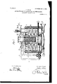
- Fig. I the perfector is arranged outside the generator, whereas in Figs. II and III it is removably fitted inside.
- the generator A and perfeotor B are concentrically arranged and heated by the furnace D.
- the combustible is supplied to the generator A through the perforated circular tube 1 2, the supply being efiected and varied according to their nature. It traverses the generator by draining'successively from the several surfaces 6.
- These can be arranged in suitable numbers beneath, above, and alongside each other as well as vertically. They may be secured by angle-irons in contact with the generatorcasing or may stand free with suitable clearance, so that the external and internalheat may operate for decomposing purposes.
- the draining-surfaces b are interrupted.
- They may consist of porous or penetrable materialfor instance, perforated sheet metal, sieves, gauze, and the like-being preferably of compressed metallic wire fabric for the purpose of presenting extensive surface and effecting a better, decomposition of the combustible.
- the combustible passed over the various draining-surfaces is subjected to a progressive distillation, the most volatile separating out first.
- the separated gases are conducted in the direction of the arrow to the perfector B for the completion of the decomposition and fixing.
- the spreading and draining surfaces may be arranged at close intervals in a generator-casing with plain surfaces or in one with an undulating formation, as shown in Fig. II. v
- Figs. II and III the perfector B is removable from above, and in the portion 0 it is provided with a charge for decomposing, reducing, and fixing the gases produced in the generator.
- the whole is inclosed in an isolating-casingE for allowing the necessary heating and can have the construction either of that of Figs. I, II, or III.
- the heat for effecting the gasification of the combustible liquids may be derived from the combustion of some of the liquid itself, from the combustion of a portion of the manufactured gas, from a mixture of liquid and gas, or by the combustion of solid fuel on a grate, and when the installation is for power purposes and the gas is employed in working internal-combustion engines then the waste heat of the exhaust-gases can be utilized for the same purpose.
- FIG. II shows means for deriving heat in each of the above-enumerated ways.
- the pipe (1 which supplies to the generator A the liquid to be vaporized, has a branch (1, commanded by a three-way cock f, whereby some of the liquid can flow into the furnaceD to be burned.
- the plug of the cockf In another position of the plug of the cockf the flow from d can be shutoff and a passage through the cock be provided for a mixture of air drawn from the atmosphere and combustible gas delivered through the nozzle 7', which gas is derived from the gasifying apparatus on the opening of a turn-cock G and conducted by the pipe e'.
- this method of ITO in yet another position, as shown in Fig. II, a mixture of liquid gas and air will be delivered to the furnace D for combustion.
- a grate is shown whereon solid fuel, coal, or coke can be burned to provide the heat requisite for the gasification.
- Fig. II a valved, which on being opened will allow excess of liquid which has not become vaporized to be withdrawn from the generator A.
- Fig. II A contrivance for effecting this object is shown in Fig. II.
- the gas escaping from C will on lifting a valve N find a passage F leading to the delivery-pipe F, and the lift of the same valve N will open a way for air to flow from an annular chamber h and mix immediately with the gas, such air finding admission to 7?. through small apertures formed in the cover-plate 5 and being raised in temperature by the waste heat of the generator.
- the gases on leaving the perfector enter a receiver X, which acts as a cooler and at the same time can serve to contain the combustibles destined to be gasified.
- the gases are hereby directly cooled, and those condensed are deposited and pass once more through the apparatus to be again vaporized.
- the apparatus may be made with the generator inside and the perfector outside, as in Fig. I, or vice versa, as in Figs. II and III, the same efiects being obtained in each.
- the heat of the exhaust-gases from the motors can be utilized for effecting the distillation by allowing them to enter at the opening D.
- the prepared gases are led away at F and, according to their intended purpose, may or may not be mixed with air.
- the remaining devices shown are well-known auxiliary apparatus universally in use.
- Fig. III is the simplest and is specially suitable for making oil-gas, distilling, &c., as by the arrangement of the receiver X, which is used to directly contain the material to be vaporized and by means of which the gases coming from the converter can be cooled, the portion liable to condense can be collected and utilized directly again for the vaporizing process, also the material to be vaporized is hereby preheated, which is very advantageous for certain substances, and the gases already distilled can be conducted away.
- a ir g r gas By directly introducing a ir g r gas in the direct process the most efficient utilization of the combustible or gas mixture is attained.
- the water-gas to be mixed is directly introduced and allowed to traverse the apparatus, as hereby an intimate mixture, and especially a fixing of the gas, results.
- nickel By means of a charge of nickel or similar material, besides perfecting the gasification, an increase in volume and a formation of gases for special purposes can be effected. For instance, spirit is preferably reduced by nickel into methane and hydrogen'and petroleum into heavy hydrocarbons and methane.
- I claim- 1 An apparatus for converting liquid com.- bustibles into gases consisting of a combination of a generator, means for sup lying li uid thereto, said generator being tted wit a succession of downward-shelving surfaces over which the liquid is spread and from which it drains to the next lower surface, means for heating said surfaces, and a perfector charged with loose permeable material in communication with said generator, means for heating the perfector and through which perfector the product of the partial distillation in the generator is required to 1pass and be therein filtered and entirely gasied. 2.
- An apparatus for converting liquid combustibles 1nto gases consisting of a combination of a generator, means for sup lying liquid thereto, said generator being 'tted with a succession of downward-shelving surfaces of undulating form and penetrable character over and through which the liquid is spread and from which it drains to the neXt lower surface, means for heating said surfaces, and a perfector charged with loose permeable materlal in communication with said generator,
- An apparatus for converting liquid combustibles lnto gases consisting of a combination of a generator, means for sup lying liquid thereto, said generator being tted with a succession of downward-shelving surfaces over which the liquid is spread and from which it drains to the next lower surface, means for heating said surfaces, a perfector charged with loose permeable material in communication with said generator, means for heating the perfector and through which perfector the product of the partial distillation in the generator is required to ass and be therein filtered and entirely gasi ed, and a cooling-receiver into which the products of distillation are led such receiver being charged with the liquid destined to be converted into gas.
Landscapes
- Chemical & Material Sciences (AREA)
- Oil, Petroleum & Natural Gas (AREA)
- Physics & Mathematics (AREA)
- Thermal Sciences (AREA)
- Engineering & Computer Science (AREA)
- Chemical Kinetics & Catalysis (AREA)
- General Chemical & Material Sciences (AREA)
- Organic Chemistry (AREA)
- Vaporization, Distillation, Condensation, Sublimation, And Cold Traps (AREA)
Description
PATENTED JAN. 2, 1906.
J. LUHNE. APPARATUS FOR VAPORIZING LIQUID COMBUSTIBLES.
APPLIUATION FILED NOV. 17, 1903. I
2 SHEETS-SHEET 1.
'W rA/Ed 6E6 PATENTBD JAN. 2,- 190a.
J. LUHNB. APPARATUS FOR VAPORIZING LIQUID GOMBUSTIBLES APPLICATION FILED NOV. 17,1903.
INVE N OQ 'mlvsm UNITED STATES PATENT OFFICE.
JOHANN LIIHNE, OF AIX-LA-CHAPELLE, GERMANY.
APPARATUS FOR VAPORIZING LIQUID COMBUSTIBLE S.
Specification of Letters Patent.
Patented J an. 2, 1906.
To all whom it may concern:
Be it known that I, JOHANN LIIHNE, of 1 0 Maxstrasse, Aix-la-Ohapelle, in the Empire of Germany, have invented a certain new and useful Improved Apparatus for Vaporizing Liquid Combustibles for Heating, Power,
Lighting, and other Purposes; and I do hereby declare the following to be a full, clear, and exact description of the invention, such as will enable others skilled in the art to which it appertains to make and use the same.
The invention relates to an apparatus for converting liquid combustibles by completely transforming or decomposing them into gases by employing two generators.
The liquid combustibles are conducted through one generator in thin films over heated distilling-surfaces draining from one to the other, which surfaces may be plain or undulated and gradually sloped, perforated, corrugated, or divided into separate parts, as most convenient to the special circumstances. While traversing these surfaces the liquid undergoes progressive distillation, and the products are preferably required to traverse another generator made in one with the ab ovementioned generator or adapted to be separated therefrom. This second generator isfilled with material adapted to transform the products of distillation completely into gas.
. For this purpose hickel-turnings and cobalt are specially suitable. This perfecting-generator simultaneously acts as afilter. It will be distinguished from the first generator by being denoted the perfector.
The accompanying drawings show by Figures I, II, and III, by way of example, vertical sections of three different forms of construction of apparatus for carrying out the process.
In Fig. I the perfector is arranged outside the generator, whereas in Figs. II and III it is removably fitted inside. The generator A and perfeotor B are concentrically arranged and heated by the furnace D. The combustible is supplied to the generator A through the perforated circular tube 1 2, the supply being efiected and varied according to their nature. It traverses the generator by draining'successively from the several surfaces 6. These can be arranged in suitable numbers beneath, above, and alongside each other as well as vertically. They may be secured by angle-irons in contact with the generatorcasing or may stand free with suitable clearance, so that the external and internalheat may operate for decomposing purposes. The draining-surfaces b are interrupted. They may consist of porous or penetrable materialfor instance, perforated sheet metal, sieves, gauze, and the like-being preferably of compressed metallic wire fabric for the purpose of presenting extensive surface and effecting a better, decomposition of the combustible. The combustible passed over the various draining-surfaces is subjected to a progressive distillation, the most volatile separating out first. The separated gases are conducted in the direction of the arrow to the perfector B for the completion of the decomposition and fixing. The spreading and draining surfaces may be arranged at close intervals in a generator-casing with plain surfaces or in one with an undulating formation, as shown in Fig. II. v
In Figs. II and III the perfector B is removable from above, and in the portion 0 it is provided with a charge for decomposing, reducing, and fixing the gases produced in the generator. The whole is inclosed in an isolating-casingE for allowing the necessary heating and can have the construction either of that of Figs. I, II, or III.
The heat for effecting the gasification of the combustible liquids may be derived from the combustion of some of the liquid itself, from the combustion of a portion of the manufactured gas, from a mixture of liquid and gas, or by the combustion of solid fuel on a grate, and when the installation is for power purposes and the gas is employed in working internal-combustion engines then the waste heat of the exhaust-gases can be utilized for the same purpose.
The drawings show means for deriving heat in each of the above-enumerated ways. In Fig. II the pipe (1, which supplies to the generator A the liquid to be vaporized, has a branch (1, commanded by a three-way cock f, whereby some of the liquid can flow into the furnaceD to be burned. In another position of the plug of the cockf the flow from d can be shutoff and a passage through the cock be provided for a mixture of air drawn from the atmosphere and combustible gas delivered through the nozzle 7', which gas is derived from the gasifying apparatus on the opening of a turn-cock G and conducted by the pipe e'. In Fig. I also this method of ITO in yet another position, as shown in Fig. II, a mixture of liquid gas and air will be delivered to the furnace D for combustion.
When heated waste gases are available, they are conducted to the furnace, as shown by the arrows in Figs. I and II, after they have first been led to the mouthpiece D. The heat thus available may be supplemented by heat derivable from the other sources when requisite.
In Fig. III a grate is shown whereon solid fuel, coal, or coke can be burned to provide the heat requisite for the gasification.
In Figs. I and II additional air for combustion is admitted by the apertures marked 3.
The products of combustion flow over the bounding-surfaces of both the generator A and the perfector B. In Fig. I they divide into two streams, a portion flowing through a central tube H and the remainder through the annular passage H, the two streams meeting in the flue-passage it, from which they are conducted to the chimney. In H and H shelves are provided on which porous incombustible material is placed, which will serve to retard the stream, render the combustion more perfect, and be a medium for conducting heat to the generator and perfector. In Fig. II the inner stream flows through an annular passage K and emerges by a number of tubes 7c and the outer stream flows by a devious path over the outside sloping surfaces of the generator A and escapes through a lateral passage or passages in casing E. (Not shown in the drawings.) In Fig. III the products of combustion first pass upward through M, then downward through M, and again upward through M to'the flue-passage h.
In Fig. II is shown a valved, which on being opened will allow excess of liquid which has not become vaporized to be withdrawn from the generator A.
If gas is being produced for use in gas-engines, it will be advantageous to mix with it some heated air as it flows awayfrom the vaporizer. A contrivance for effecting this object is shown in Fig. II. The gas escaping from C will on lifting a valve N find a passage F leading to the delivery-pipe F, and the lift of the same valve N will open a way for air to flow from an annular chamber h and mix immediately with the gas, such air finding admission to 7?. through small apertures formed in the cover-plate 5 and being raised in temperature by the waste heat of the generator.
By means of this apparatus maintained at a sufiiciently high temperature there will occur a complete decomposition of the combustible into gas. Substances carried over from the generator and not yet vaporized will be decomposed on traversing the perfector. The perfector acts also as a filter and prevents entrance of the exterior atmosphere and effects a more uniform vaporization.
The gases on leaving the perfector enter a receiver X, which acts as a cooler and at the same time can serve to contain the combustibles destined to be gasified. The gases are hereby directly cooled, and those condensed are deposited and pass once more through the apparatus to be again vaporized.
The apparatus may be made with the generator inside and the perfector outside, as in Fig. I, or vice versa, as in Figs. II and III, the same efiects being obtained in each. When employed for power purposes, the heat of the exhaust-gases from the motors can be utilized for effecting the distillation by allowing them to enter at the opening D. The prepared gases are led away at F and, according to their intended purpose, may or may not be mixed with air. The remaining devices shown are well-known auxiliary apparatus universally in use.
The mode of operation is the same in all three examples. That shown in Fig. III is the simplest and is specially suitable for making oil-gas, distilling, &c., as by the arrangement of the receiver X, which is used to directly contain the material to be vaporized and by means of which the gases coming from the converter can be cooled, the portion liable to condense can be collected and utilized directly again for the vaporizing process, also the material to be vaporized is hereby preheated, which is very advantageous for certain substances, and the gases already distilled can be conducted away. By directly introducing a ir g r gas in the direct process the most efficient utilization of the combustible or gas mixture is attained.
When producing mixed gas consisting, for instance, of waterggasandioihgas, preferably the water-gas to be mixed is directly introduced and allowed to traverse the apparatus, as hereby an intimate mixture, and especially a fixing of the gas, results.
By means of a charge of nickel or similar material, besides perfecting the gasification, an increase in volume and a formation of gases for special purposes can be effected. For instance, spirit is preferably reduced by nickel into methane and hydrogen'and petroleum into heavy hydrocarbons and methane.
The individual stages of decomposition and vaporization process cannot be sufiiciently separated to exactly determine the changes that occur. It is, however, essential that by means of the arrangement of the diffusing-surfaces where the easily volatile substances immediately separate the substances more difficult to decompose gradually approach the region of higher temperature and the decomposition is gradually advanced and a much greater efficiency is attained.
I claim- 1. An apparatus for converting liquid com.- bustibles into gases consisting of a combination of a generator, means for sup lying li uid thereto, said generator being tted wit a succession of downward-shelving surfaces over which the liquid is spread and from which it drains to the next lower surface, means for heating said surfaces, and a perfector charged with loose permeable material in communication with said generator, means for heating the perfector and through which perfector the product of the partial distillation in the generator is required to 1pass and be therein filtered and entirely gasied. 2. An apparatus for converting liquid combustibles 1nto gases consisting of a combination of a generator, means for sup lying liquid thereto, said generator being 'tted with a succession of downward-shelving surfaces of undulating form and penetrable character over and through which the liquid is spread and from which it drains to the neXt lower surface, means for heating said surfaces, and a perfector charged with loose permeable materlal in communication with said generator,
means for heating the perfector and through which perfector the product of the partial distillation in the generator is required to 1piass and be therein filtered and entirely gasi- 3. An apparatus for converting liquid combustibles lnto gases consisting of a combination of a generator, means for sup lying liquid thereto, said generator being tted with a succession of downward-shelving surfaces over which the liquid is spread and from which it drains to the next lower surface, means for heating said surfaces, a perfector charged with loose permeable material in communication with said generator, means for heating the perfector and through which perfector the product of the partial distillation in the generator is required to ass and be therein filtered and entirely gasi ed, and a cooling-receiver into which the products of distillation are led such receiver being charged with the liquid destined to be converted into gas.
In testimony whereof I have hereunto set my hand in the presence of two subscribing witnesses.
JOHANN LUHNE.
Witnesses:
JosEPH TANSEN, HENRY QUADFLIEG.
Priority Applications (1)
| Application Number | Priority Date | Filing Date | Title |
|---|---|---|---|
| US18153103A US809200A (en) | 1903-11-17 | 1903-11-17 | Apparatus for vaporizing liquid combustibles. |
Applications Claiming Priority (1)
| Application Number | Priority Date | Filing Date | Title |
|---|---|---|---|
| US18153103A US809200A (en) | 1903-11-17 | 1903-11-17 | Apparatus for vaporizing liquid combustibles. |
Publications (1)
| Publication Number | Publication Date |
|---|---|
| US809200A true US809200A (en) | 1906-01-02 |
Family
ID=2877681
Family Applications (1)
| Application Number | Title | Priority Date | Filing Date |
|---|---|---|---|
| US18153103A Expired - Lifetime US809200A (en) | 1903-11-17 | 1903-11-17 | Apparatus for vaporizing liquid combustibles. |
Country Status (1)
| Country | Link |
|---|---|
| US (1) | US809200A (en) |
-
1903
- 1903-11-17 US US18153103A patent/US809200A/en not_active Expired - Lifetime
Similar Documents
| Publication | Publication Date | Title |
|---|---|---|
| US809200A (en) | Apparatus for vaporizing liquid combustibles. | |
| US2205554A (en) | Method for generating oil gas | |
| US1128549A (en) | Process of making gas. | |
| US1000768A (en) | Process of and apparatus for making gas. | |
| US766554A (en) | Process of manufacturing gas. | |
| US331903A (en) | Process of manufacturing illuminating-gas | |
| US269162A (en) | piebson | |
| US925415A (en) | Gas-producer. | |
| US289279A (en) | Leadley | |
| US532451A (en) | Apparatus for manufacturing gas | |
| US766553A (en) | Apparatus for the manufacture of gas and coke. | |
| US345437A (en) | Gas retort and furnace | |
| US468747A (en) | Process of and apparatus for the manufacture of illuminating-gas | |
| US324685A (en) | hanlon | |
| US404520A (en) | clark | |
| US920903A (en) | Method of and apparatus for converting liquid hydrocarbons into gas or vapor. | |
| US533696A (en) | young | |
| US1046541A (en) | Method of generating oil-gas for explosive-engines. | |
| US341622A (en) | aecher | |
| US478459A (en) | Method of manufacturing gas | |
| US429309A (en) | Apparatus for the manufacture of gas | |
| US789266A (en) | Apparatus for manufacturing gas. | |
| US1172925A (en) | Process of producing hydrogen or illuminating and heating gas. | |
| US992944A (en) | Method of enriching gas for illuminating purposes. | |
| US403921A (en) | George k |