US809181A - Centering device for draw-bars. - Google Patents
Centering device for draw-bars. Download PDFInfo
- Publication number
- US809181A US809181A US26412905A US1905264129A US809181A US 809181 A US809181 A US 809181A US 26412905 A US26412905 A US 26412905A US 1905264129 A US1905264129 A US 1905264129A US 809181 A US809181 A US 809181A
- Authority
- US
- United States
- Prior art keywords
- draw
- follower
- bar
- spring
- support
- Prior art date
- Legal status (The legal status is an assumption and is not a legal conclusion. Google has not performed a legal analysis and makes no representation as to the accuracy of the status listed.)
- Expired - Lifetime
Links
- 210000003371 toe Anatomy 0.000 description 9
- 210000002683 foot Anatomy 0.000 description 6
- 210000003739 neck Anatomy 0.000 description 5
- 238000010276 construction Methods 0.000 description 4
- 210000003414 extremity Anatomy 0.000 description 3
- XEEYBQQBJWHFJM-UHFFFAOYSA-N iron Substances [Fe] XEEYBQQBJWHFJM-UHFFFAOYSA-N 0.000 description 2
- 229910052742 iron Inorganic materials 0.000 description 2
- 230000006835 compression Effects 0.000 description 1
- 238000007906 compression Methods 0.000 description 1
- 239000000446 fuel Substances 0.000 description 1
Images

Classifications
-
- B—PERFORMING OPERATIONS; TRANSPORTING
- B61—RAILWAYS
- B61G—COUPLINGS; DRAUGHT AND BUFFING APPLIANCES
- B61G7/00—Details or accessories
- B61G7/10—Mounting of the couplings on the vehicle
Definitions
- the drawebars are mounted to swing about centers somewhere between the ends of the cars and the center plins of their trucks, so as to be capable of sufcient lateral movement about said centers to enable them to assume positions in line with each other and on or parallel with the lines of strains to which they are subjected.
- the advantages of 'a draw-bar capable of such lateral movement over those that are not are generally understood by those skilled in the art.
- the draw-bars are yieldingly held normally in the center line of the car-body and in another type they are yieldingly held normally at right angles to the transom of the truck.
- the draw-bar strains are transmitted by the draft-rigging to draftarms and the center of lateral movement of the draw-bar is located a considerable distance from the center pin of the truck, while in the second type the draw-bar strains are transmitted to the center sills through rigging including a bar which is pivoted only a short distance from the center pin of the truck.
- the draw-bars may aline, as described, but in the second type the draw-bars may approach more closely a line drawn from truck-center to truck-.center, and thus to a greater extent prevent lat'- eral strains upon the car-frames and trucks.
- the present invention is not limited to the construction or character of the draw-bar or its rigging nor to the location of its center of lateral movement g but on the contrary it is applicable to any draw-bar that is capable of lateral movement; but for the purposes of illustration I have selected the type of drawbar first above described.
- the object of the invention is to provide a centering device of improved construction; and the invention consists in the features of ⁇ novelty hereinafter described.
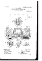
- Figure 1 is a plan view of a centering vdevice embodying the invention, the positions of the draw-bar and draft-arms or center walls being indicated by dotted lines and one-half of the cover-plate being omitted.
- Fig. 2 is a vertical section thereon on the line 2 2, Fig. 1.
- Fig. 3 is a sectional elevation thereof, one half being shown in elevation and the other in vertical section.
- Fig. 4 is a vertical section of the spring-casing and cover on the line 4 4, Fig. 1, looking in the direction of the arrow.
- Fig. 5 is an elevation of one of the followers.
- Fig. 6 is a section thereon on the line 6 6, Fig. 5.
- A indicates the draw-bar, and B parts by which the improved centering device is supported. These parts may be considered either as draft-arms oras the center sills or as any other parts of the car that will aord adequate support forr the improved centering device, it being understood that said device may be attached to any suitable part of the car without changing the construction otherwise than as may be necessary to accommodate the chosen support, and here it may be statedthat the device may be applied to or incorporated in the car structure when the car is being built or it maybe made as a se arate attachment to be applied to cars a ter they are built.
- the plate C is a heavy plate, preferably of the outline shown in Fig. 1, perforated for the passage of bolts D, by which it is secured to the under side of the draft-arms B, a second and preferably somewhat lighter plate E being interposed.
- the plate C has on its under side a spring casing or support comprising IOO IIO
- each chamber F that are of substantially U shape in vertical transverse section, excepting that each has along its bottom a longitudinal slot or opening
- Each chamber is closed at its outer end by a wall, which is perpendicular to the longitudinal center of the chamber and against which one end of the spring bears and at its inner end by a wall f, which preferably slopes and forms a stop for the follower.
- the chambers open through out their length through the plate C, (or, in other words, the plate has slots conterminous with the tops of the chambers) and the chambers and slots are constructed upon a curve, the center of which is coincident with the center of lateral movement of the drawbar.
- the chambers and the slots in the plate C terminate at their inner ends some distance from the mid-length of the plate, thus leaving an uninterrupted portion C, and this portion C is strengthened by webs c, depending from its under side and at their ends joining the inner ends f of the chambers.
- the plate C has upwardly-extending projections, which provide vertical shoulders C, that engage the outer sides of the draft-arms and aid the bolts D in preventing the endwise movement of the plate laterally with respect to the car.
- the plate E extends from one to the other of the shoulders C, is otherwise of the same outline as the plate C, and is provided with holes for the passage of the bolts D. Both plates are provided with holes for the passage of rivets G or other devices by which they are secured together.
- the plate E is also provided with slots e, which extend from its extremities inward toward its mid-length, terminating at about the inner ends of the chambers. These slots are curved and central with respect to the chambers. They are of suflicient width to receive the necks or shanks of a pair of followers H, while at the same time they leave portions of the plate projecting over the sides of the chambers to provide guides E for the followers.
- Each of the followers has a portion 7L, (hereinafter called the head,) adapted to engage the side of the draw-bar, a portion h', (hereinafter called the foot,) adapted to engage the inner end of the compression-spring I, contained in one of the chambers, and a neck or shank 7L, connecting the head and foot and occupying the slot e between the guides E.
- the vertical engaging face of the head h is preferably rounded off, and its back is provided with strengthening-webs. It has below its rounded face a toe or extension H, and at its sides it is extended beyond the neck to rovide shoulders J.
- the toe and the shou ders rest upon parallel ribs orflanges e on the plate E, so that the head is capable of sliding laterally thereon, and the toe extends beneath the draw-bar, so that, in addition to providing an extended bearing-surface for thehead, it carries or aids in carrying the draw-bar, so that the latterv is relieved in whole or in part of wear incident to its lateral movement, and it prevents the follower from canting.
- the extremity of the toe is beveled off, so as to avoid an abrupt surface or shoulder against which the draw-bar might strike in returning to central position.
- the engaging face of the foot h is flat, and its back is provided with strengthening-webs. It is extended at the sides of the neck beyond the slot e to provide shoulders J, that are adapted to engage the under sides of the guides E if the foot is lifted.
- the sides of the neck 7L are made upon curves parallel with the curved inner edges of the guides E and are rounded 0HT to avoid corners that might dig into the guides.
- the plate E is provided with a third and somewhat higher rib e and upon which under some circumstances the draw-bar may rest. If necessary, the draft-arms may be recessed, as at l), to permit the necessary outward movement of the followers.
- the plates C and E perform the functions of a carrier-iron for supporting the draw-bar; but this is not essential, and, if desired, the draw-bar may be independently supported.
- the guides E are preferably curved, as described, for the purpose of reducing frietion; but in its broadest aspect the invention is not limited to curved guides.
- lateral is used in this specification with respect to the length of the car.
- follower is used to indicate 4any movable device that is interposed between the draw-bar and a spring for transmitting strains from one to the other.
- a follower adapted to engage the draw-bar, a support having ribs upon which the follower rests and having later- IOO ally-disposed guides engaging the follower, a spring for exerting lateral pressure upon the follower, and means for supporting the spring, substantially as described.
- a follower adapted to engage the draw-bar, a support having ribs upon which the follower rests and having a higher rib adapted to engage and support the drawbar, a spring for exerting lateral pressure upon the follower, and means for supporting the spring, substantially as described.
- a support therefor, a spring and means for supporting the spring, said follower having a head adapted to engage the draw-bar, and a foot adapted to engage the spring, and said support having a slot through which the follower extends substantially as described.
- a laterally-movable follower adapted to engage the draw-bar, said follower having a toe adapted to extend beneath and support the draw-bar, a support vupon which the follower is slidably mounted and upon which the toe bears, whereby it is supported and in turn supports the drawbar, means for confining the follower to lateral movement, and means for yieldingly resisting the movement of the follower, substantially as described.
- a pair of independently-movable followers adapted to engage theA drawbar, said followers having toes adapted to extend beneath and support the draw-bar, a support upon which the followers are slidably mounted and upon which the toes bear, means for confining the followers to lateral movement, and means for yieldingly resisting their outward movement, substantially as described.
Landscapes
- Engineering & Computer Science (AREA)
- Mechanical Engineering (AREA)
- Forklifts And Lifting Vehicles (AREA)
Description
GENTERIN PATBNTBD 111112, 1906.
M. A. GARRBTT. G DEVICE POR DRAW BARS.
APPLICATION FILED JUNE 7,1905.
2 SHEETS-SHEET 1.
11111111IIIIII1I' I 1 1 1 1 I 1 I M. A. GARRETT.
GENTERING DEVICE POR DRAW BARS.
APPLIOATION FILED JUNE 7.1905. A
PATENTED JAN. 2, 1906.
2 SHEETS-SHEET wwllguquuv UNITED STATES PATENT OFFICE.
CENTERING DEVICE FOR DRAW-BARS.
Specification of Letters Patent.
Patented Jan. 2, 1906.
Applitiation filed June 7,1905. Serial No. 264,129.
To all whom it may concern:
Be it known that I, MYERS A.' GARRETT, a citizen of the United States, residing at Chicago, in the county of Cook and State of Illinois, have invented certain new and useful Improvements in Centering Devices for Draw-Bars, of which the following is a specication.
In order to prevent excessive lateral strains upon coupled drawebars, especially when' the cars are passing over a track having either a simple or a reverse curve, the drawebars are mounted to swing about centers somewhere between the ends of the cars and the center plins of their trucks, so as to be capable of sufcient lateral movement about said centers to enable them to assume positions in line with each other and on or parallel with the lines of strains to which they are subjected. The advantages of 'a draw-bar capable of such lateral movement over those that are not are generally understood by those skilled in the art. Chief among them may be mentioned the lessening of breakage'and wear and tear upon various parts of the cars and also upon the track-rails, a saving of fuel incident to the lessening ofvthevtraction friction, and the lessening of accidents. While this lateral movement of the draw-bars is therefore highly desirable, it is also desirable that when uncoupled the draw-bars stand in such positions that the couplers will meet and automatically engage when the cars come together, and a device or attachment for yieldingly holding them in these positions and for automatically returning them thereto upon the removal of the force that moved them therefrom forms the subject of the present invention. Laterally movable drawbars equipped with such devices are not broadly new. In one type now in use the draw-barsare yieldingly held normally in the center line of the car-body and in another type they are yieldingly held normally at right angles to the transom of the truck. In the type first named the draw-bar strains are transmitted by the draft-rigging to draftarms and the center of lateral movement of the draw-bar is located a considerable distance from the center pin of the truck, while in the second type the draw-bar strains are transmitted to the center sills through rigging including a bar which is pivoted only a short distance from the center pin of the truck. In both types the draw-bars may aline, as described, but in the second type the draw-bars may approach more closely a line drawn from truck-center to truck-.center, and thus to a greater extent prevent lat'- eral strains upon the car-frames and trucks. I desire to have it understood, however, that the present invention is not limited to the construction or character of the draw-bar or its rigging nor to the location of its center of lateral movement g but on the contrary it is applicable to any draw-bar that is capable of lateral movement; but for the purposes of illustration I have selected the type of drawbar first above described.
The object of the invention is to provide a centering device of improved construction; and the invention consists in the features of\ novelty hereinafter described.
In the accompanying drawings, which are Y made a part of this specification, Figure 1 is a plan view of a centering vdevice embodying the invention, the positions of the draw-bar and draft-arms or center walls being indicated by dotted lines and one-half of the cover-plate being omitted. Fig. 2 is a vertical section thereon on the line 2 2, Fig. 1. Fig. 3 is a sectional elevation thereof, one half being shown in elevation and the other in vertical section. Fig. 4 is a vertical section of the spring-casing and cover on the line 4 4, Fig. 1, looking in the direction of the arrow. Fig. 5 is an elevation of one of the followers. Fig. 6 is a section thereon on the line 6 6, Fig. 5.
A indicates the draw-bar, and B parts by which the improved centering device is supported. These parts may be considered either as draft-arms oras the center sills or as any other parts of the car that will aord adequate support forr the improved centering device, it being understood that said device may be attached to any suitable part of the car without changing the construction otherwise than as may be necessary to accommodate the chosen support, and here it may be statedthat the device may be applied to or incorporated in the car structure when the car is being built or it maybe made as a se arate attachment to be applied to cars a ter they are built.
C is a heavy plate, preferably of the outline shown in Fig. 1, perforated for the passage of bolts D, by which it is secured to the under side of the draft-arms B, a second and preferably somewhat lighter plate E being interposed. The plate C has on its under side a spring casing or support comprising IOO IIO
two chambers F, that are of substantially U shape in vertical transverse section, excepting that each has along its bottom a longitudinal slot or opening Each chamber is closed at its outer end by a wall, which is perpendicular to the longitudinal center of the chamber and against which one end of the spring bears and at its inner end by a wall f, which preferably slopes and forms a stop for the follower. The chambers open through out their length through the plate C, (or, in other words, the plate has slots conterminous with the tops of the chambers) and the chambers and slots are constructed upon a curve, the center of which is coincident with the center of lateral movement of the drawbar. The chambers and the slots in the plate C terminate at their inner ends some distance from the mid-length of the plate, thus leaving an uninterrupted portion C, and this portion C is strengthened by webs c, depending from its under side and at their ends joining the inner ends f of the chambers. At its extremities the plate C has upwardly-extending projections, which provide vertical shoulders C, that engage the outer sides of the draft-arms and aid the bolts D in preventing the endwise movement of the plate laterally with respect to the car.
The plate E extends from one to the other of the shoulders C, is otherwise of the same outline as the plate C, and is provided with holes for the passage of the bolts D. Both plates are provided with holes for the passage of rivets G or other devices by which they are secured together. The plate E is also provided with slots e, which extend from its extremities inward toward its mid-length, terminating at about the inner ends of the chambers. These slots are curved and central with respect to the chambers. They are of suflicient width to receive the necks or shanks of a pair of followers H, while at the same time they leave portions of the plate projecting over the sides of the chambers to provide guides E for the followers. Each of the followers has a portion 7L, (hereinafter called the head,) adapted to engage the side of the draw-bar, a portion h', (hereinafter called the foot,) adapted to engage the inner end of the compression-spring I, contained in one of the chambers, and a neck or shank 7L, connecting the head and foot and occupying the slot e between the guides E.
The vertical engaging face of the head h is preferably rounded off, and its back is provided with strengthening-webs. It has below its rounded face a toe or extension H, and at its sides it is extended beyond the neck to rovide shoulders J. The toe and the shou ders rest upon parallel ribs orflanges e on the plate E, so that the head is capable of sliding laterally thereon, and the toe extends beneath the draw-bar, so that, in addition to providing an extended bearing-surface for thehead, it carries or aids in carrying the draw-bar, so that the latterv is relieved in whole or in part of wear incident to its lateral movement, and it prevents the follower from canting. The extremity of the toe is beveled off, so as to avoid an abrupt surface or shoulder against which the draw-bar might strike in returning to central position. Y The engaging face of the foot h is flat, and its back is provided with strengthening-webs. It is extended at the sides of the neck beyond the slot e to provide shoulders J, that are adapted to engage the under sides of the guides E if the foot is lifted. The sides of the neck 7L are made upon curves parallel with the curved inner edges of the guides E and are rounded 0HT to avoid corners that might dig into the guides. The plate E is provided with a third and somewhat higher rib e and upon which under some circumstances the draw-bar may rest. If necessary, the draft-arms may be recessed, as at l), to permit the necessary outward movement of the followers.
The operation of the improved device is so apparent from the drawings and the foregoing description that but little more need be said concerning it. The drawings show the parts in normal positions and with the draw-bar central. While in these positions the springs are under little or no compression. Vhen the draw-bar is moved laterally, one of the followers is moved with it and the corresponding spring is compressed. Upon the removal of the lateral pressure upon the draw-bar the spring will expand to normal condition and in doing so will, acting through the follower, return the draw-bar to centralposition.
In the construction shown in the drawings the plates C and E perform the functions of a carrier-iron for supporting the draw-bar; but this is not essential, and, if desired, the draw-bar may be independently supported. Again, the guides E are preferably curved, as described, for the purpose of reducing frietion; but in its broadest aspect the invention is not limited to curved guides.
rlhe term lateral is used in this specification with respect to the length of the car. The term follower is used to indicate 4any movable device that is interposed between the draw-bar and a spring for transmitting strains from one to the other.
What I claim as new is l. In a device of the class described, the combination of a laterally-movable follower adapted. to engage the draw-bar, laterallydisposed curved guides engaging the follower, a spring adapted to exert lateral pressure upon the follower, and means for supporting the follower and spring, substantially as described.
2. In a device of the class described the combination of a follower adapted to engage the draw-bar, a support having ribs upon which the follower rests and having later- IOO ally-disposed guides engaging the follower, a spring for exerting lateral pressure upon the follower, and means for supporting the spring, substantially as described.
8. In a device of the class described, the combination of a follower adapted to engage the draw-bar, a support for the follower having a raised rib, adapted to directly engage and support the draw-bar, a spring for exerting lateral pressure upon the follower, and a support for the spring, substantially as described. Y
4. In a device of the class described the combination of a follower adapted to engage the draw-bar, a support having ribs upon which the follower rests and having a higher rib adapted to engage and support the drawbar, a spring for exerting lateral pressure upon the follower, and means for supporting the spring, substantially as described.
5. In a device of the class described, the
combination of a laterally-movable follower,
a support therefor, a spring and means for supporting the spring, said follower having a head adapted to engage the draw-bar, and a foot adapted to engage the spring, and said support having a slot through which the follower extends substantially as described.
6. In a device of the class described, the combination of a laterally-movable follower, a support therefor, a spring, and means for supporting the spring, said follower having a head adapted to engage the draw-bar and a foot adapted to engage the spring, and said support having a curved slot through which the follower extends, substantially as described.
7. In a device of the class described, the combination of a support, a follower extending above and below the support, a spring adapted to engage the follower below the support, and means for supporting the spring, the support having a laterally disposed curved guide for the follower, substantially as described.
8. In a device of the class described, the combination of a support in the nature of a carry-iron, a pair of independent followers supported by and extending above and below the support, a spring adapted to engage the follower below the support and a casing containing the spring, substantially as described.
9. In a device of the class described, the combination of a laterally-movable follower, a spring for exerting lateral pressure upon the follower, a chamber containing the spring and open at top and a slotted plate forming a partial cover for the casing and a support for the follower, substantially as described.
10. In a device of the class described the combination of a pair of independently-movable followers adapted to engage the drawbar, means for supporting said followers and confining them to lateral curvilinear movement, independent springs for exerting lateral pressure upon'the followers, and means for supporting the springs, substantially as described.
11. In a device of the class described the combination of a pair of independently-movable followers, independent springs for exerting lateral pressure upon the followers, and means for supporting the followers and springs, said supporting means including a plate having vertical shoulders adapted -to engage the draft-arms, substantially as described.
12. In a device of the class described the combination of a pair of independently-movable followers, springs for exerting lateral pressure upon the followers'and means for supporting the followers and springs, said supporting means including a plate having beneath it chambers for containing the springs, substantially as described.
13. In a device of the class described, the combination of a pair of independent laterally-movable followers having vertical faces adapted to engage the opposite sides of the draw-bar, each of said followers having a horizontal toe adapted to extend beneath and support the draw-bar, and a spring adapted to exert lateral pressure upon the follower, substantially as described.
14. In a device of the class described, the combination of a laterally-movable follower adapted to engage the draw-bar, said follower having a toe adapted to extend beneath and support the draw-bar, a support vupon which the follower is slidably mounted and upon which the toe bears, whereby it is supported and in turn supports the drawbar, means for confining the follower to lateral movement, and means for yieldingly resisting the movement of the follower, substantially as described.
15. In a device of the class described, the combination of a pair of independently-movable followers adapted to engage theA drawbar, said followers having toes adapted to extend beneath and support the draw-bar, a support upon which the followers are slidably mounted and upon which the toes bear, means for confining the followers to lateral movement, and means for yieldingly resisting their outward movement, substantially as described.
MYERS A. GARRETT. Witnesses:
D. M..Ho1 xiNs, JEssIE E. Li'rsEY.
IOO
IIO
Priority Applications (1)
| Application Number | Priority Date | Filing Date | Title |
|---|---|---|---|
| US26412905A US809181A (en) | 1905-06-07 | 1905-06-07 | Centering device for draw-bars. |
Applications Claiming Priority (1)
| Application Number | Priority Date | Filing Date | Title |
|---|---|---|---|
| US26412905A US809181A (en) | 1905-06-07 | 1905-06-07 | Centering device for draw-bars. |
Publications (1)
| Publication Number | Publication Date |
|---|---|
| US809181A true US809181A (en) | 1906-01-02 |
Family
ID=2877662
Family Applications (1)
| Application Number | Title | Priority Date | Filing Date |
|---|---|---|---|
| US26412905A Expired - Lifetime US809181A (en) | 1905-06-07 | 1905-06-07 | Centering device for draw-bars. |
Country Status (1)
| Country | Link |
|---|---|
| US (1) | US809181A (en) |
-
1905
- 1905-06-07 US US26412905A patent/US809181A/en not_active Expired - Lifetime
Similar Documents
| Publication | Publication Date | Title |
|---|---|---|
| US809181A (en) | Centering device for draw-bars. | |
| US634219A (en) | Draw-bar-attaching means. | |
| US854042A (en) | Draft-rigging. | |
| US1070446A (en) | Draft and buffing mechanism for railway-cars. | |
| US1804345A (en) | Railway draft gear | |
| US1122734A (en) | Car-coupling. | |
| US2003221A (en) | Railway draft appliance | |
| US369975A (en) | westbbook | |
| US1220265A (en) | Railroad-car draft-rigging. | |
| US1535315A (en) | Draft rigging | |
| US473014A (en) | Half to louis r | |
| US363783A (en) | Benjamin f | |
| US1492779A (en) | Friction draft gear | |
| US859446A (en) | Draw-bar-centering mechanism. | |
| US1426221A (en) | Draft rigging | |
| US626881A (en) | Draft-rigging | |
| US1060698A (en) | Friction draft-rigging for railway-cars. | |
| US1302074A (en) | Friction shock-absorbing mechanism. | |
| US1149399A (en) | Draft-rigging for railway-cars. | |
| US1000312A (en) | Draft-rigging. | |
| US1286072A (en) | Draw-bar and yoke connection. | |
| US533609A (en) | Willard f | |
| US787445A (en) | Draft or buffing gear or rigging for cars. | |
| US644384A (en) | Draft-rigging for engines and tenders. | |
| US1004064A (en) | Coupling-centering device. |