US809170A - Collapsible table. - Google Patents
Collapsible table. Download PDFInfo
- Publication number
- US809170A US809170A US21072404A US1904210724A US809170A US 809170 A US809170 A US 809170A US 21072404 A US21072404 A US 21072404A US 1904210724 A US1904210724 A US 1904210724A US 809170 A US809170 A US 809170A
- Authority
- US
- United States
- Prior art keywords
- shield
- sections
- bar
- legs
- frame
- Prior art date
- Legal status (The legal status is an assumption and is not a legal conclusion. Google has not performed a legal analysis and makes no representation as to the accuracy of the status listed.)
- Expired - Lifetime
Links
- 238000010276 construction Methods 0.000 description 2
- 230000005484 gravity Effects 0.000 description 1
- 238000010409 ironing Methods 0.000 description 1
- 230000004048 modification Effects 0.000 description 1
- 238000012986 modification Methods 0.000 description 1
Images

Classifications
-
- D—TEXTILES; PAPER
- D06—TREATMENT OF TEXTILES OR THE LIKE; LAUNDERING; FLEXIBLE MATERIALS NOT OTHERWISE PROVIDED FOR
- D06F—LAUNDERING, DRYING, IRONING, PRESSING OR FOLDING TEXTILE ARTICLES
- D06F81/00—Ironing boards
- D06F81/006—Ironing boards with fabric support or garment rack
Definitions
- My invention relates to new and useful improvements in collapsible tables; and its object is to provide a device of this character which can be folded into compact form and which is provided with a detachable shield which is adapted to be-placed in position under the table and which can be used for holding clothes or other articles.
- the invention comprises a supporting-frame having crossed legs pivoted to the ends thereof, and these legs are adapted to be folded upon the frame, so that the table may occupy a small space, if desired, when not in use.
- the top of the table is removable, and detachably mounted upon the frame below the cover is a shield formed of two oppositelydisposed sections hinged together and forming jaws adjacent the hinges which are adapted to clamp upon the frame.
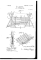
- FIG. 1 is a perspective view of an ironingtable constructed in accordance with my invention.
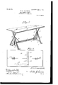
- Fig. 2 is a vertical transverse section therethrough.
- Fig. 3 is a front elevation of the table, showing the same folded.
- Fig. 4 is a section on line 4 4, Fig. 3.
- Fig. 5 is a detail view of one end of the frame of the table.
- Fig. 6 is a perspective view of the shield detached.
- 1 is a cross-bar having uprights 2 at its ends, which are suitably braced by means of rods 3.
- Pins 4 extend from the ends of the uprights and form pivots for cross-strips 5, which connect the crossed legs 6 of the table at points adjacent their ends. As these strips 5 are arranged upon one face of the legs 6, it will be understood that said legs can be swung upon pins 4, so as to assume positions parallel with the bar 1.
- a shield of novel construction is adapted to be supported by the bar 1.
- This shield is formed of two sections, each of which consists of parallel slats 7, which are secured to supporting strips 8, having their ends in alinernent with the outer edges of the end slats.
- These supporting-strips are preferably tapered from their inner to their outer ends, as shown in the drawings, and the adjoining edges of the two sections of the shield are connected by straps 9, which are hinged at their ends to leaves 10, fastened in any suitable manner to the shield-sections.
- the two adjoining large ends of each pair of supporting-strips 8 form jaws which are adapted to bear upon opposite sides of the bar 1, and these jaws clamp upon the bar by reason of the pressure exerted by the weight of the sections of the shield.
- a cover 11 which is large at one end'and small at the other end, forming an ironing-board, is adapted to be placed upon the upper ends of the legs 6.
- This cover has an aperture 12 therein for the reception of one of the pins 4, although, if desired, two apertures may be provided for receiving both of the upper pins 4. It will of course be understood that before the cover 11 can be placed in position it is necessary to first swing the legs 6 into position at right angles to the bar 1. The sections of the shield can then be folded upon each other and placed above the bar 1 with the straps 9 upon said bar.
- This shield serves to catch any articles which may be suspended from the board 11, so as to keep them from the floor and, if desired, can be used as a receptacle for sprinkled clothes.
- a table-top, a supporting-frame therefor including a horizontal strip, and a remov- I able shield comprising a pair of sections pivotally connected, said sections having portions adapted to conjointly engage and clamp the strip between them.
- a table-top, a supporting-frame therefor including a horizontal strip, and a removable shield comprising a pair of sections pivotally connected, said sections having transverse cleats spaced at their inner adjacent ends and adapted to conjointly receive and I0 clamp the strip between them.
Landscapes
- Engineering & Computer Science (AREA)
- Textile Engineering (AREA)
- Treatment Of Fiber Materials (AREA)
Description
No. 809,170. PATENTED JAN. 2, 1906. W. L. BROADWELL.
GOLLAPSIBLB TABLE.
APPLICATION FILED JUNE 1, 1904.
3 SHEETS-SHEET 1.
No. 809,170. PATENTED JAN. 2, 1906.
- W. L. BROADWELL.
COLLAPSIBLE TABLE.
\ APPLICATION FILED JUNE 1, 1904.
3 SHEETS-SHEBT 2.
3 SHEETS-SHEET 3.
UNITED STATES PATENT OFFICE.
Specification of Letters Patent.
Patented Jan. 2, 1906.
Application filed June 1, 1904. Serial No. 210.724.
To all whom it may concern-.-
Be it known that I ,WALTER L. BROADVVELL, a citizen of the United States, residing at South Norfolk, in the county of Norfolk and State of Virginia, have invented new and useful Improvements in Collapsible Ironing- Tables, of which the following is a specification.
My invention relates to new and useful improvements in collapsible tables; and its object is to provide a device of this character which can be folded into compact form and which is provided with a detachable shield which is adapted to be-placed in position under the table and which can be used for holding clothes or other articles.
With the above and other objects in view the invention comprises a supporting-frame having crossed legs pivoted to the ends thereof, and these legs are adapted to be folded upon the frame, so that the table may occupy a small space, if desired, when not in use. The top of the table is removable, and detachably mounted upon the frame below the cover is a shield formed of two oppositelydisposed sections hinged together and forming jaws adjacent the hinges which are adapted to clamp upon the frame.
The invention consists of the novel construction and combination of parts hereinafter more fully described and claimed, and illustrated in the accompanying drawings, showing the preferred form of my invention, and in which- Figure 1 is a perspective view of an ironingtable constructed in accordance with my invention. Fig. 2 is a vertical transverse section therethrough. Fig. 3 is a front elevation of the table, showing the same folded. Fig. 4 is a section on line 4 4, Fig. 3. Fig. 5 is a detail view of one end of the frame of the table. Fig. 6 is a perspective view of the shield detached.
Referring to the figures by numerals of reference, 1 is a cross-bar having uprights 2 at its ends, which are suitably braced by means of rods 3. Pins 4 extend from the ends of the uprights and form pivots for cross-strips 5, which connect the crossed legs 6 of the table at points adjacent their ends. As these strips 5 are arranged upon one face of the legs 6, it will be understood that said legs can be swung upon pins 4, so as to assume positions parallel with the bar 1.
A shield of novel construction is adapted to be supported by the bar 1. This shield is formed of two sections, each of which consists of parallel slats 7, which are secured to supporting strips 8, having their ends in alinernent with the outer edges of the end slats. These supporting-strips are preferably tapered from their inner to their outer ends, as shown in the drawings, and the adjoining edges of the two sections of the shield are connected by straps 9, which are hinged at their ends to leaves 10, fastened in any suitable manner to the shield-sections. The two adjoining large ends of each pair of supporting-strips 8 form jaws which are adapted to bear upon opposite sides of the bar 1, and these jaws clamp upon the bar by reason of the pressure exerted by the weight of the sections of the shield.
When the table herein described is to be used for ironing, a cover 11, which is large at one end'and small at the other end, forming an ironing-board, is adapted to be placed upon the upper ends of the legs 6. This cover has an aperture 12 therein for the reception of one of the pins 4, although, if desired, two apertures may be provided for receiving both of the upper pins 4. It will of course be understood that before the cover 11 can be placed in position it is necessary to first swing the legs 6 into position at right angles to the bar 1. The sections of the shield can then be folded upon each other and placed above the bar 1 with the straps 9 upon said bar. The sections of the shield are then permitted to swing downward by gravity, and the large ends of the supportingstrips 8 clamp the bar 1 therebetween, and the shield will thus assume the position shown in Figs. 1 and 2. This shield serves to catch any articles which may be suspended from the board 11, so as to keep them from the floor and, if desired, can be used as a receptacle for sprinkled clothes.
In the foregoing description I have shown the preferred form of myinvention; but I do not limit myself thereto, as I am aware that modifications may be made therein without departing from the spirit or sacrificing any of the advantages thereof, and I therefore reserve the right to make suchchanges as fairly fall within the scope of my invention.
Having thus described the invention, what is claimed as new is 1. A table-top, a supporting-frame therefor including a horizontal strip, and a remov- I able shield comprising a pair of sections pivotally connected, said sections having portions adapted to conjointly engage and clamp the strip between them.
2. A table-top, a supporting-frame therefor including a horizontal strip, and a removable shield comprising a pair of sections pivotally connected, said sections having transverse cleats spaced at their inner adjacent ends and adapted to conjointly receive and I0 clamp the strip between them.
In testimony whereof I aflix my signature in presence of two witnesses.
WALTER L. BROADWELL.
Witnesses:
NORMAN F. ALLEN, G. D. PARKER, Jr.
Priority Applications (1)
| Application Number | Priority Date | Filing Date | Title |
|---|---|---|---|
| US21072404A US809170A (en) | 1904-06-01 | 1904-06-01 | Collapsible table. |
Applications Claiming Priority (1)
| Application Number | Priority Date | Filing Date | Title |
|---|---|---|---|
| US21072404A US809170A (en) | 1904-06-01 | 1904-06-01 | Collapsible table. |
Publications (1)
| Publication Number | Publication Date |
|---|---|
| US809170A true US809170A (en) | 1906-01-02 |
Family
ID=2877651
Family Applications (1)
| Application Number | Title | Priority Date | Filing Date |
|---|---|---|---|
| US21072404A Expired - Lifetime US809170A (en) | 1904-06-01 | 1904-06-01 | Collapsible table. |
Country Status (1)
| Country | Link |
|---|---|
| US (1) | US809170A (en) |
Cited By (1)
| Publication number | Priority date | Publication date | Assignee | Title |
|---|---|---|---|---|
| US2707874A (en) * | 1950-03-18 | 1955-05-10 | Bill Glover Inc | Garment spotting machine |
-
1904
- 1904-06-01 US US21072404A patent/US809170A/en not_active Expired - Lifetime
Cited By (1)
| Publication number | Priority date | Publication date | Assignee | Title |
|---|---|---|---|---|
| US2707874A (en) * | 1950-03-18 | 1955-05-10 | Bill Glover Inc | Garment spotting machine |
Similar Documents
| Publication | Publication Date | Title |
|---|---|---|
| US3087624A (en) | Display device | |
| US1556624A (en) | Supporting frame | |
| US809170A (en) | Collapsible table. | |
| US284286A (en) | Folding clothes-rack | |
| US2070826A (en) | Dish rack | |
| US1645179A (en) | Clothes drier | |
| US930491A (en) | Ironing-cabinet. | |
| US2085572A (en) | Portable window platform | |
| US1429456A (en) | Knockdown wardrobe | |
| US2084661A (en) | Curtain drying and stretching rack | |
| US2316433A (en) | Clothes drying rack | |
| US908000A (en) | Folding rack. | |
| US1435148A (en) | Combined bassinet and swing | |
| US543025A (en) | Display-rack | |
| US493134A (en) | Blackboard and desk | |
| US716393A (en) | Clothes-rack. | |
| US1512522A (en) | Combination dressing table and bathtub | |
| US1658929A (en) | Combination ironing board and clothes drier | |
| US1529840A (en) | Folding tub rack | |
| US649861A (en) | Folding ironing-table. | |
| US527809A (en) | John reading | |
| US1155967A (en) | Clothes-rack. | |
| US1049682A (en) | Combined step-ladder and ironing-board. | |
| US235403A (en) | Skirt-ironing board | |
| US1340265A (en) | Folding ironing-board |