US8091518B2 - Cooling passage partition for an internal combustion engine - Google Patents
Cooling passage partition for an internal combustion engine Download PDFInfo
- Publication number
- US8091518B2 US8091518B2 US12/309,609 US30960907A US8091518B2 US 8091518 B2 US8091518 B2 US 8091518B2 US 30960907 A US30960907 A US 30960907A US 8091518 B2 US8091518 B2 US 8091518B2
- Authority
- US
- United States
- Prior art keywords
- cooling passage
- passage
- partition member
- cooling
- separating wall
- Prior art date
- Legal status (The legal status is an assumption and is not a legal conclusion. Google has not performed a legal analysis and makes no representation as to the accuracy of the status listed.)
- Expired - Fee Related, expires
Links
Images


Classifications
-
- F—MECHANICAL ENGINEERING; LIGHTING; HEATING; WEAPONS; BLASTING
- F02—COMBUSTION ENGINES; HOT-GAS OR COMBUSTION-PRODUCT ENGINE PLANTS
- F02F—CYLINDERS, PISTONS OR CASINGS, FOR COMBUSTION ENGINES; ARRANGEMENTS OF SEALINGS IN COMBUSTION ENGINES
- F02F1/00—Cylinders; Cylinder heads
- F02F1/02—Cylinders; Cylinder heads having cooling means
- F02F1/10—Cylinders; Cylinder heads having cooling means for liquid cooling
- F02F1/14—Cylinders with means for directing, guiding or distributing liquid stream
-
- F—MECHANICAL ENGINEERING; LIGHTING; HEATING; WEAPONS; BLASTING
- F01—MACHINES OR ENGINES IN GENERAL; ENGINE PLANTS IN GENERAL; STEAM ENGINES
- F01P—COOLING OF MACHINES OR ENGINES IN GENERAL; COOLING OF INTERNAL-COMBUSTION ENGINES
- F01P3/00—Liquid cooling
- F01P3/02—Arrangements for cooling cylinders or cylinder heads
-
- F—MECHANICAL ENGINEERING; LIGHTING; HEATING; WEAPONS; BLASTING
- F02—COMBUSTION ENGINES; HOT-GAS OR COMBUSTION-PRODUCT ENGINE PLANTS
- F02F—CYLINDERS, PISTONS OR CASINGS, FOR COMBUSTION ENGINES; ARRANGEMENTS OF SEALINGS IN COMBUSTION ENGINES
- F02F1/00—Cylinders; Cylinder heads
- F02F1/02—Cylinders; Cylinder heads having cooling means
- F02F1/10—Cylinders; Cylinder heads having cooling means for liquid cooling
-
- F—MECHANICAL ENGINEERING; LIGHTING; HEATING; WEAPONS; BLASTING
- F01—MACHINES OR ENGINES IN GENERAL; ENGINE PLANTS IN GENERAL; STEAM ENGINES
- F01P—COOLING OF MACHINES OR ENGINES IN GENERAL; COOLING OF INTERNAL-COMBUSTION ENGINES
- F01P3/00—Liquid cooling
- F01P3/02—Arrangements for cooling cylinders or cylinder heads
- F01P2003/021—Cooling cylinders
-
- Y—GENERAL TAGGING OF NEW TECHNOLOGICAL DEVELOPMENTS; GENERAL TAGGING OF CROSS-SECTIONAL TECHNOLOGIES SPANNING OVER SEVERAL SECTIONS OF THE IPC; TECHNICAL SUBJECTS COVERED BY FORMER USPC CROSS-REFERENCE ART COLLECTIONS [XRACs] AND DIGESTS
- Y10—TECHNICAL SUBJECTS COVERED BY FORMER USPC
- Y10T—TECHNICAL SUBJECTS COVERED BY FORMER US CLASSIFICATION
- Y10T29/00—Metal working
- Y10T29/49—Method of mechanical manufacture
- Y10T29/49229—Prime mover or fluid pump making
- Y10T29/49231—I.C. [internal combustion] engine making
Definitions
- the present invention relates to a partition member that is provided in a cooling passage defined in a cylinder block of an internal combustion engine and divides the cooling passage into a plurality of passages, a cooling mechanism using the partition member, and a method for forming the cooling mechanism.
- Japanese Laid-Open Patent Publication No. 2002-13440 describes a technique in which a spacer formed of, for example, resin is arranged in a bottom portion of a water jacket (a groove-like cooling passage) of a cylinder block. The technique thus adjusts the flow resistance of the coolant flowing in the water jacket and uniformly cools a bore wall.
- coolant is allowed to flow only in a path located upward from the spacer after the flow resistance of the coolant has been adjusted. It is thus difficult to perform highly accurate temperature adjustment in the cylinder block, or, particularly, in a cylinder bore forming body.
- the spacer is formed of resin with relatively high rigidity, great load must be applied to the spacer when the spacer is inserted into the water jacket and arranged in the bottom portion of the water jacket. This makes it difficult to manufacture a cooling mechanism of an internal combustion engine.
- a partition member provided in a cylinder block of an internal combustion engine has a groove-like cooling passage through which a cooling heat medium flows.
- the partition member is arranged in the groove-like cooling passage.
- the cooling passage extends to encompass cylinder bores of the cylinder block, and has a bottom surface, a pair of opposing inner surfaces, and an opening located opposite to the bottom surface.
- the partition member includes a separating wall and a flexible lip member. The separating wall divides the cooling passage into an inner passage and an outer passage.
- the inner passage is located close to the cylinder bores, and the outer passage is located outside of the inner passage.
- the separating wall has a lower end portion facing the bottom surface of the cooling passage and an upper end portion located opposite to the lower end portion.
- the height from the bottom surface of the cooling passage to the upper end portion of the separating wall is less than the depth of the cooling passage.
- the flexible lip member extends from the separating wall toward the opening in such a manner that, when the partition member is arranged in the cooling passage, the lip member contacts one of the inner surfaces at an intermediate position in a direction along the depth of the cooling passage.
- the lip member has a distal edge portion that extends beyond the one inner surface before the partition member is arranged in the cooling passage. When the partition member is arranged in the cooling passage, the distal edge portion contacts the one inner surface due to force produced through flexible shape restoration of the lip member.
- a cooling mechanism of an internal combustion engine includes a groove-like cooling passage, which is provided in a cylinder block of an internal combustion engine and allows flow of a cooling heat medium to flow therethrough, and a partition member provided in the cooling passage.
- the cooling passage extends to encompass cylinder bores of the cylinder block.
- the cooling passage has a bottom surface, a pair of opposing inner surfaces, and an opening located opposite to the bottom surface.
- the partition member includes a separating wall and a flexible lip member. The separating wall divides the cooling passage into an inner passage and an outer passage.
- the inner passage is located close to the cylinder bores, and the outer passage is located outside of the inner passage.
- the separating wall has a lower end portion facing the bottom surface of the cooling passage and an upper end portion located opposite to the lower end portion.
- a contact portion that contacts the bottom surface of the cooling passage is provided on the lower end portion.
- the lip member has a distal edge portion that extends beyond the inner surface closer to the cylinder bores before the partition member is arranged in the cooling passage.
- the distal edge portion contacts the inner surface closer to the cylinder bores due to force produced through flexible shape restoration of the lip member.
- the cylinder block has a first supply port for supplying cooling heat medium to the cooling passage. The first supply port is opened to the inner passage.
- a method for forming a cooling mechanism of an internal combustion engine includes: providing a groove-like cooling passage through which a cooling heat medium flows in a cylinder block of the engine, wherein the cooling passage extends to encompass cylinder bores of the cylinder block, and wherein the cooling passage has a bottom surface, a pair of opposing inner surfaces, and an opening located opposite to the bottom surface; preparing a partition member that is arranged in the cooling passage, the partition member having a separating wall and a flexible lip member, wherein the separating wall divides the cooling passage into an inner passage and an outer passage, the inner passage being located close to the cylinder bores, the outer passage being located outside of the inner passage, wherein the separating wall has a lower end portion facing the bottom surface of the cooling passage and an upper end portion located opposite to the lower end portion, wherein a contact portion that contacts the bottom surface of the cooling passage is provided on the lower end portion, and wherein, when the partition partition
- FIG. 1A is a plan view showing a partition member according to a first embodiment of the present invention
- FIG. 1B is a front view showing the partition member shown in FIG. 1A ;
- FIG. 1C is a bottom view showing the partition member shown in FIG. 1A ;
- FIG. 1D is a perspective view showing the partition member shown in FIG. 1A ;
- FIG. 1E is a left side view showing the partition member shown in FIG. 1A ;
- FIG. 1F is a right side view showing the partition member shown in FIG. 1A ;
- FIG. 2 is an exploded perspective view showing the partition member shown in FIGS. 1A to 1F ;
- FIG. 3 is a perspective view showing a cylinder block having the partition member shown in FIGS. 1A to 1F provided in a water jacket;
- FIG. 4 is a longitudinal cross-sectional view showing the position of the partition member shown in FIGS. 1A to 1F in relation to the position of the water jacket;
- FIG. 5 is a longitudinal cross-sectional view along a direction in which bores are arranged in the cylinder block, illustrating the partition member of FIGS. 1A to 1F arranged in the water jacket;
- FIGS. 6A , 6 B, 6 C, and 6 D are views representing a method of molding the partition member shown in FIGS. 1A to 1F ;
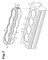
- FIG. 7 is a perspective view representing a method for inserting the partition member shown in FIGS. 1A to 1F into the water jacket;
- FIGS. 8A , 8 B, 8 C, 8 D, and 8 E are views for explaining the configuration of a partition member according to a second embodiment of the present invention.
- FIG. 9 is a longitudinal cross-sectional view showing the position of the partition member shown in FIGS. 8A to 8E in relation to the position of the water jacket;
- FIGS. 10A , 10 B, 10 C, and 10 D are views for explaining a method for molding the partition member of FIGS. 8 to 8E ;
- FIG. 11 is a perspective view showing a partition member according to another embodiment of the present invention.
- FIGS. 12A and 12B are longitudinal cross-sectional views each showing the position of a partition member according to another embodiment of the present invention in relation to the position of a water jacket;
- FIGS. 13A and 13B are longitudinal cross-sectional views each showing the position of a partition member according to another embodiment of the present invention in relation to the position of a water jacket;
- FIG. 14 is a longitudinal cross-sectional view showing the position of a partition member according to another embodiment of the present invention in relation to the position of a water jacket.
- a partition member 2 shown in FIGS. 1A to 1F is provided in a water jacket (a groove-like cooling passage in which cooling heat medium flows) 12 , which is arranged in a cylinder block 10 of an engine shown in FIG. 3 .
- the cylinder block 10 is an open-deck type cylinder block having four cylinder bores 14 b that are aligned along a line.
- the cylinder block 10 also has a cylinder bore forming body (a cylinder wall) 14 , which defines the cylinder bores 14 b .
- the cylinder bore 14 b located leftmost in FIG. 3 is defined as a first cylinder bore # 1 .
- the cylinder bore 14 b adjacent rightward from the first cylinder bore # 1 is defined as a second cylinder bore # 2 .
- the cylinder bore 14 b adjacent rightward from the second cylinder bore # 2 is defined as a third cylinder bore # 3 .
- the cylinder bore 14 b adjacent rightward from the third cylinder bore # 3 is defined as a fourth cylinder bore # 4 .
- the partition member 2 has a base member 4 , a flexible lip member 6 , and a flexible contact member 8 .
- the base member 4 is shaped in correspondence with an outer circumferential surface 14 a (inner surface) of the cylinder bore forming body 14 .
- the base member 4 maintains the shape of the partition member 2 as a whole and is formed of a material having higher rigidity than the material of the lip member 6 .
- the base member 4 is formed of olefin-based resin.
- the base member 4 is arranged in a water jacket 12 of the cylinder block 10 .
- the thickness of the base member 4 is smaller than the width of the water jacket 12 .
- the width of the water jacket 12 refers to the distance between the outer circumferential surface 14 a of the cylinder bore forming body 14 and an inner circumferential surface 16 a (inner surface) of an outer circumferential wall 16 of the cylinder block 10 .
- the partition member 2 divides the interior of the water jacket 12 into an inner passage 12 a and an outer passage 12 b .
- the inner passage 12 a is defined by the partition member 2 and the cylinder bore forming body 14 .
- the outer passage 12 b is defined by the partition member 2 and the outer circumferential wall 16 .
- a guide wall 4 a is formed in the base member 4 at a position corresponding to the first cylinder bore # 1 .
- the height of the guide wall 4 a is set in such a manner that the top surface of the guide wall 4 a becomes flush with the top surface of the cylinder block 10 in which an opening of the water jacket 12 is defined.
- the guide wall 4 a guides coolant (cooling heat medium) from the water jacket 12 to a water jacket (not shown) provided in a cylinder head.
- a blocking wall 4 b is formed integrally with the guide wall 4 a .
- a first opening 10 a is defined in a portion of the outer circumferential wall 16 adjacent to the blocking wall 4 b .
- the coolant is introduced into the water jacket 12 through the first opening 10 a .
- the blocking wall 4 b projects from the guide wall 4 a toward the outer circumferential wall 16 to block the outer passage 12 b at a position adjacent to the first opening 10 a.
- a top surface 4 c of the upper end portion of the base member 4 other than the guide wall 4 a and the blocking wall 4 b has a uniform height and is located lower than the top surface of the cylinder block 10 in which the opening of the water jacket 12 is defined.
- the top surface 4 c is located, for example, at a height equal to approximately two thirds of the depth of the water jacket 12 with respect to a bottom surface 12 d of the water jacket 12 .
- the height from the bottom surface 12 d of the water jacket 12 to the upper end portion (the top surface 4 c ) of the base member 4 is less than the depth of the water jacket 12 .
- the lip member 6 is bonded with the top surface 4 c.
- a through hole 4 d is defined in a portion of the base member 4 opposite to the guide wall 4 a , or the portion of the base member 4 corresponding to the fourth cylinder bore # 4 , and extends horizontally through the base member 4 .
- a seal ring 4 e which is formed by a rubber-like elastic body, is bonded with the outer circumferential surface of the base member 4 in such a manner that the seal ring 4 e encompasses the through hole 4 d . As shown in FIG. 5 , with the partition member 2 received in the water jacket 12 , the seal ring 4 e is held in tight contact with the inner circumferential surface 16 a of the outer circumferential wall 16 .
- a second opening 10 b which receives heated water, is defined in the outer circumferential wall 16 .
- the sealing effect of the seal ring 4 e prevents the heater water from flowing into the outer passage 12 b through the second opening 10 b and introduces the heated water to the inner passage 12 a.
- the lip member 6 is formed of flexible material.
- the lip member 6 of the first embodiment is formed of olefin-based elastomer. With reference to FIG. 2 , the lip member 6 has a shape corresponding to the top surface 4 c of the base member 4 .
- the lip member 6 has a base portion 6 a , which is bonded with the top surface 4 c of the base member 4 , and a lip portion 6 b inclined upwardly from the base portion 6 a .
- the lip portion 6 b is formed in such a manner that, when the partition member 2 is not received in the water jacket 12 , the surface area of the portion of the lip portion 6 b encompassed by a distal edge portion 6 c becomes smaller than the surface area of the portion of the cylinder bore forming body 14 encompassed by the outer circumferential surface 14 a .
- the distal edge portion 6 c extends beyond the outer circumferential surface 14 a of the cylinder bore forming body 14 . That is, when the partition member 2 is received in the water jacket 12 , the lip portion 6 b contacts the outer circumferential surface 14 a at an intermediate position with respect to the direction along the depth of the water jacket 12 .
- the lip portion 6 b is formed of flexible material, the lip portion 6 b easily flexes. Thus, with the partition member 2 received in the water jacket 12 , the lip portion 6 b is easily expanded by the outer circumferential surface 14 a of the cylinder bore forming body 14 . As a result, the lip portion 6 b is prevented from receiving great resistance force from the outer circumferential surface 14 a of the cylinder bore forming body 14 .
- the partition member 2 When the partition member 2 is inserted into the water jacket 12 , the partition member 2 as a whole is received in the water jacket 12 with the lip member 6 held in contact with the outer circumferential surface 14 a of the cylinder bore forming body 14 . In this manner, the partition member is forcibly guided to an optimal position in the water jacket 12 .
- the force produced through flexible shape restoration of the lip portion 6 b maintains the contact between the distal edge portion 6 c of the lip portion 6 b and the outer circumferential surface 14 a of the cylinder bore forming body 14 .
- the inner passage 12 a and the outer passage 12 b are maintained in a mutually separate state in the water jacket 12 .
- the lip portion 6 b extends inward and diagonally upward from the base portion 6 a , the partition member 2 does not easily separate from the water jacket 12 .
- the distal edge portion 6 c of the lip portion 6 b contacts the outer circumferential surface 14 a at an intermediate position with respect to the depth.
- an upper area 12 c in the water jacket 12 is located in the outer passage 12 b . That is, the outer passage 12 b is defined by a wall corresponding to the entire portion of the inner circumferential surface 16 a of the outer circumferential wall 16 and, in the upper area 12 c , a wall corresponding to an upper portion of the outer circumferential surface 14 a of the cylinder bore forming body 14 .
- the contact member 8 is shaped identically with the base member 4 .
- the thickness of the contact member 8 is smaller than the thickness of the base member 4 .
- the contact member 8 and the lip member 6 are formed of the same material. This improves tight contact performance of the partition member 2 with respect to the bottom surface 12 d of the water jacket 12 .
- the combination of the contact member 8 and the base member 4 except for the guide wall 4 a and the blocking wall 4 b corresponds to a separating wall recited in claims.
- the lip member 6 and the contact member 8 are bonded with the base member 4 using adhesive or through welding or mechanical engagement.
- the partition member 2 may be formed as an integral body through die rotary molding (coinjection molding).
- the base member 4 is provided through injection molding using a core die D 1 , a cavity die D 2 , and sliding dies D 3 , D 4 .
- a second step referring to FIG. 6B , the dies D 2 to D 4 are removed from the core die D 1 .
- a third step as illustrated in FIG. 6C , a cavity die D 5 for the lip member 6 and sliding dies D 6 , D 7 for the contact member 8 are combined with the core D 1 including the completed base member 4 .
- material is injected into the space for forming the lip member 6 and the contact member 8 , which is provided by combining the core die D 1 , the cavity die D 5 , and the sliding dies D 6 , D 7 . In this manner, the lip member 6 and the contact member 8 are provided through injection molding.
- the lip member 6 and the contact member 8 are bonded with the base member 4 in such a manner that the partition member 2 is completed.
- the seal ring 4 e is also provided together with the lip member 6 and the contact member 8 through injection molding.
- the obtained partition member 2 is inserted into the water jacket 12 of the cylinder block 10 through an opening defined in the deck surface so that the contact portion 8 , which is formed at the lower end of the base member 4 , contacts the bottom surface 12 d of the water jacket 12 .
- a cylinder head is then secured to the cylinder block 10 . This causes the upper end of the guide wall 4 a to contact the cylinder head (or a gasket) so that the partition member 2 becomes fixed in the water jacket 12 .
- coolant is sent from a cooling water pump into the water jacket 12 through the first opening 10 a ( FIG. 3 ) and then flows through the outer passage 12 b . Since the cross-sectional area of the outer passage 12 b is relatively great in the upper area 12 c , the coolant flows mainly in the upper area 12 c .
- the blocking wall 4 b causes the coolant to flow in a counterclockwise direction in the cylinder block 10 as viewed from above. The coolant then reaches the guide wall 4 a . Afterwards, the coolant is sent into the water jacket provided in the cylinder head by the guide wall 4 a and the blocking wall 4 b.
- heated water pre-heating heat medium
- the heated water flowing in the inner passage 12 a heats a lower portion of the cylinder bore forming body 14 to cause efficient heat transmission. Accordingly, the cylinder bores 14 b are heated quickly and uniformly.
- the first embodiment has the following advantages.
- the base member 4 is formed of the material with higher rigidity than the rigidity of the lip member 6 .
- the above-described shape of the base member 4 facilitates installation of the partition member 2 in the water jacket 12 . Since the width of the contact member 8 is smaller than the width of a lower end surface 4 f of the base member 4 , the contact member 8 is easily arranged in the water jacket 12 .
- the lip member 6 Since the lip member 6 is flexible, the lip member 6 does not receive great resistance force from the outer circumferential surface 14 a of the cylinder bore forming body 14 when the partition member 2 is inserted into the water jacket 12 . Thus, the partition member 2 is inserted into the water jacket 12 only with small sliding resistance force. Further, in insertion of the partition member 2 into the water jacket 12 , the lip member 6 functions to guide the partition member 2 as a whole to an optimal position in the water jacket 12 . Also, after the partition member 2 is received in the water jacket 12 , the lip member 6 prevents the partition member 2 from easily separating from the water jacket 12 .
- an engine cooling mechanism is easily formed through insertion of the partition member 2 into the water jacket 12 through the opening in the deck surface in such a manner that the contact member 8 contacts the bottom surface 12 d of the water jacket 12 .
- the partition member 2 is efficiently arranged in the water jacket 12 .
- the force of the flexible shape restoration of the lip member 6 causes the lip member 6 to maintain contact between the distal edge portion 6 c and the outer circumferential surface 14 a of the cylinder bore forming body 14 . Since the contact member 8 is arranged at the lower end surface 4 f of the base member 4 , the partition member 2 and the water jacket 12 are held in contact with each other with an increased tightness. This sufficiently ensures independent flows of coolant in the inner passage 12 a and the outer passage 12 b . Thus, during the operation of the engine, the difference in the temperature in the up-and-down direction in the cylinder bore forming body 14 is decreased through introduction of the coolant into the outer passage 12 b through the first opening 10 a .
- the cylinder bores 14 b are efficiently heated through introduction of the heated water into the inner passage 12 a through the seal ring 4 e and the through hole 4 d . Accordingly, under any circumstance, the temperature is easily controlled with improved accuracy in the up-and-down direction of the cylinder bore forming body 14 .
- the partition member 2 is thus easily manufactured.
- a partition member 102 according to a second embodiment of the present invention will be explained with reference to FIGS. 8A to 10 .
- the partition member 102 of the second embodiment is different from the partition member 2 of the first embodiment.
- a lip member 106 and a contact member 108 of the second embodiment are identical with the lip member 6 and the contact member 108 of the first embodiment.
- a cylinder block 110 of the second embodiment is identical with the cylinder block 10 of the first embodiment.
- the base member 104 has a guide wall 104 a and a blocking wall 104 b , which are provided at positions in an continuous wall 104 e corresponding to a first cylinder bore # 1 .
- the base member 104 also has a through hole 104 c and a seal ring 104 d , which are provided at positions corresponding to a fourth cylinder bore # 4 .
- An upper frame 104 f , a lower frame 104 g , and an intermediate frame 104 h are provided in the continuous wall 104 e of the base member 104 .
- the upper frame 104 f , the lower frame 104 g , and the intermediate frame 104 h each function as a rib that reinforces the continuous wall 104 e .
- a lip member 106 is bonded with the top surface of the upper frame 104 f .
- a contact member 108 is bonded with the lower surface of the lower frame 104 g .
- the upper frame 104 f and the lower frame 104 g integrate the lip member 106 and the contact member 108 , respectively, with the base member 104 .
- the thicknesses of the upper frame 104 f , the lower frame 104 g , and the intermediate frame 104 h become gradually smaller in a radially outward direction of the continuous wall 104 e .
- Such decreased thicknesses of the frames 104 f , 104 g , and 104 h provide a draft necessary for removing sliding dies D 13 , D 14 from a core die D 11 .
- the thickness of the contact member 108 may become gradually smaller from the continuous wall 104 e toward a bottom surface 112 d of the water jacket 112 .
- the continuous wall 104 e has a guide slope 104 i , which is arranged adjacent to the blocking wall 104 b . If coolant is introduced between the blocking wall 104 b and the inclined surface of the guide slope 104 i with the partition member 102 received in the water jacket 112 , the blocking wall 104 b causes the coolant to flow in a counterclockwise direction as viewed from above, as in the first embodiment. In this state, the guide slope 104 i smoothly guides the coolant to an upper area 112 c in the water jacket 112 , which is a portion of an outer passage 112 b.
- the partition member 102 is formed by a method similar to the method for forming the partition member 2 of the first embodiment. That is, the lip member 106 and the contact member 108 may be bonded with the base member 104 using adhesive or through welding or mechanical engagement. Alternatively, such bonding may be brought about through the die rotary molding, as illustrated in FIG. 10 .
- the procedure of the die rotary molding of the second embodiment is similar to the corresponding procedure of the first embodiment.
- the base member 104 is formed through injection molding using the core die D 11 , a cavity die D 12 , and the sliding dies D 13 , D 14 .
- the dies D 12 to D 14 are removed from the core die D 11 .
- a cavity die D 15 for the lip member 106 and sliding dies D 16 , D 17 for the contact member 108 are combined with the core die D 11 having the completed base member 104 .
- a fourth step referring to FIG.
- material is injected into the space for forming the lip member 106 and the contact member 108 , which is provided by the core die D 11 , the cavity die D 15 , and the sliding dies D 16 , D 17 that are combined together.
- the lip member 106 and the contact member 108 are formed through injection molding.
- the lip member 106 and the contact member 108 are bonded with the base member 104 and the partition member 102 is completed.
- the thus formed partition member 102 is inserted into the water jacket 112 in the cylinder block 110 , as illustrated in FIG. 9 .
- a cylinder head is secured to the cylinder block 110 in such a manner that the upper end of the guide wall 104 a contacts the cylinder head (or a gasket). This fixes the partition member 102 in the water jacket 112 .
- the second embodiment has the following advantages.
- the upper frame 104 f , the lower frame 104 g , and the intermediate frame 104 h each function as a rib reinforcing the continuous wall 104 e .
- the partition member 102 maintains sufficiently high strength.
- the guide wall 4 a guides the coolant and reliably fixes the partition member 2 as a whole to the cylinder block 10 .
- projections 204 f , 204 g each having a height equal to the height of the guide wall 204 a may be provided in addition to the guide wall 204 a , which is formed in the portion of the base member 204 corresponding to the first cylinder bore # 1 .
- the projections 204 f , 204 g project from portions of the base member 204 corresponding to a fourth cylinder bore # 4 . This reliably fixes the partition member 202 at the side corresponding to the fourth cylinder bore. # 4 .
- Such structure may be employed also in the partition member 102 of the second embodiment.
- FIGS. 12A to 13B illustrate partition members according to other embodiments of the present invention.
- a partition member 302 shown in FIG. 12A does not include a member corresponding to the contact member 8 of the partition member 2 of the first embodiment.
- a base member 304 formed of olefin-based resin directly contacts a bottom surface 312 d of a water jacket 312 in a cylinder block 310 . Since the base member 304 has rigidity higher than the rigidity of the lip member 306 , tightness of contact between the partition member 303 and the bottom surface 312 d is slightly decreased. However, independent flows of coolant in an inner passage 312 a and an outer passage 312 b are sufficiently maintained.
- the partition member 302 has the advantages equivalent to the advantages of the partition member 2 of the first embodiment. Also, since the partition member 302 does not employ the contact member 8 formed of elastomer, the material cost and the manufacturing cost are saved.
- a partition member 402 illustrated in FIG. 12B includes a contact member 408 shaped identically with a lip member 406 .
- the contact member 408 includes a lip portion 408 a and a distal edge portion 408 b .
- the lip portion 408 a projects toward an opening defined in a water jacket 412 .
- the distal edge portion 408 b is provided at a distal end of the lip portion 408 a and contacts an inner surface 416 a of the water jacket 412 .
- the distal edge portion 408 b is located outward from the inner surface 416 a of the water jacket 412 .
- the partition member 402 has the advantages equivalent to the advantages of the partition member 2 of the first embodiment. Further, since the base member 404 of the partition member 402 has decreased thickness, the weight of the engine is decreased.
- a partition member 502 shown in FIG. 13A is provided by stacking two partition members 502 a , 502 b in an up-and-down direction in a water jacket 512 .
- the partition member 502 a has a base member 504 a and a lip member 506 , which is formed integrally with the base member 504 a .
- the partition member 502 b has a base member 504 b and a lip member 507 , which is formed integrally with the base member 504 b .
- the base member 504 a and the base member 504 b are each configured identically with the partition member 302 shown in FIG. 12A . However, the height of each base member 504 a , 504 b is approximately the half the height of the partition member 302 .
- Each of the lip members 506 , 507 is formed of flexible material as in the above-illustrated embodiments.
- the partition member 502 Through stacking of the partition members 502 a , 502 b in the up-and-down direction, the partition member 502 defines an inner passage 512 a and an inner passage 513 a , which are separate from each other, and an outer passage 512 b , which is separate from the inner passages 512 a , 513 a . Heater water may be introduced into one or both of the inner passages 512 a , 513 a .
- the partition member 502 has the advantages equivalent to the advantages of the partition member 2 of the first embodiment. Further, since the base members 504 a , 504 b are formed as an integral body, the inner passage 512 a between the lip members 506 , 507 is sealed with improved tightness.
- the height of the base member 504 a and the height of the base member 504 b may differ from each other. In correspondence with the difference between the height of the base member 504 a and the height of the base member 504 b , the ratio of the cross-sectional area of the inner passage 513 a with respect to the cross-sectional area of the inner passage 512 a is adjusted.
- a partition member 602 illustrated in FIG. 13B has a flexible member 606 provided by forming a lip member 606 a and a contact member 606 b as an integral body.
- the flexible member 606 is formed integrally with a side surface of a base member 604 in such a manner as to extend beyond the base member 604 in an up-and-down direction.
- the partition member 602 has the advantages equivalent to the advantages of the partition member 2 of the first embodiment.
- a lip portion of a lip member contacts an outer circumferential surface of a cylinder bore forming body.
- a lip portion 706 a of a lip member 706 may contact an inner circumferential surface 716 a of an outer circumferential wall 716 of a cylinder block 710 as illustrated in FIG. 14 .
Landscapes
- Engineering & Computer Science (AREA)
- Chemical & Material Sciences (AREA)
- Combustion & Propulsion (AREA)
- Mechanical Engineering (AREA)
- General Engineering & Computer Science (AREA)
- Cylinder Crankcases Of Internal Combustion Engines (AREA)
Abstract
Description
Claims (9)
Applications Claiming Priority (3)
| Application Number | Priority Date | Filing Date | Title |
|---|---|---|---|
| JP2006207439A JP4851258B2 (en) | 2006-07-31 | 2006-07-31 | Heat medium passage partition member for cooling internal combustion engine, internal combustion engine cooling mechanism, and internal combustion engine cooling mechanism forming method |
| JP2006-207439 | 2006-07-31 | ||
| PCT/JP2007/065210 WO2008016127A1 (en) | 2006-07-31 | 2007-07-27 | Partition member for cooling passage of internal combustion engine, cooling mechanism of internal combustion engine, and method for forming the cooling mechanism |
Publications (2)
| Publication Number | Publication Date |
|---|---|
| US20090194046A1 US20090194046A1 (en) | 2009-08-06 |
| US8091518B2 true US8091518B2 (en) | 2012-01-10 |
Family
ID=38754562
Family Applications (1)
| Application Number | Title | Priority Date | Filing Date |
|---|---|---|---|
| US12/309,609 Expired - Fee Related US8091518B2 (en) | 2006-07-31 | 2007-07-27 | Cooling passage partition for an internal combustion engine |
Country Status (6)
| Country | Link |
|---|---|
| US (1) | US8091518B2 (en) |
| EP (1) | EP2049783B1 (en) |
| JP (1) | JP4851258B2 (en) |
| KR (1) | KR101056008B1 (en) |
| CN (1) | CN101495741B (en) |
| WO (1) | WO2008016127A1 (en) |
Cited By (8)
| Publication number | Priority date | Publication date | Assignee | Title |
|---|---|---|---|---|
| US20100024748A1 (en) * | 2008-08-04 | 2010-02-04 | Hyundai Motor Company | Cooling device and insert for water jacket of internal combustion engine |
| US20110132295A1 (en) * | 2009-11-19 | 2011-06-09 | Honda Motor Co., Ltd. | Cooling structure for internal combustion engine |
| US20130160725A1 (en) * | 2010-06-22 | 2013-06-27 | Nichias Corporation | Heat retention member for cylinder bore wall, internal combustion engine, and automobile |
| US20150285125A1 (en) * | 2014-04-02 | 2015-10-08 | GM Global Technology Operations LLC | Cylinder block cooling jacket insert allowing separated cooling circuits |
| US9316162B2 (en) | 2012-12-12 | 2016-04-19 | Ford Global Technologies, Llc | Method of controlling a fuel supply system of an engine of a motor vehicle |
| US9442034B2 (en) | 2013-11-22 | 2016-09-13 | Ford Global Technologies, Llc | Engine knock signal transmissive element |
| US20180363587A1 (en) * | 2015-11-12 | 2018-12-20 | Nichias Corporation | Cylinder bore wall thermal insulator, internal combustion engine, and automobile |
| DE112014000931B4 (en) * | 2013-02-21 | 2020-09-10 | Mazda Motor Corporation | Cooling device for multi-cylinder engine |
Families Citing this family (52)
| Publication number | Priority date | Publication date | Assignee | Title |
|---|---|---|---|---|
| JP2008128133A (en) * | 2006-11-22 | 2008-06-05 | Toyota Motor Corp | Heat medium heat transfer control device for cooling internal combustion engine |
| KR100980620B1 (en) | 2008-06-11 | 2010-09-07 | 동아공업 주식회사 | Sealing structure of water jacket insert |
| KR101163824B1 (en) | 2009-04-07 | 2012-07-09 | 현대자동차주식회사 | Cooling device and insert for water jacket of internal combustion engine |
| JP5468476B2 (en) * | 2010-06-28 | 2014-04-09 | ニチアス株式会社 | Thermal insulation structure for cylinder bore wall and internal combustion engine |
| JP5227374B2 (en) * | 2010-08-03 | 2013-07-03 | 本田技研工業株式会社 | Spacer |
| JP5948268B2 (en) | 2013-03-15 | 2016-07-06 | ニチアス株式会社 | Insulating member for cylinder bore wall |
| JP6064858B2 (en) * | 2013-10-03 | 2017-01-25 | トヨタ自動車株式会社 | Internal combustion engine |
| JP6277399B2 (en) * | 2013-10-11 | 2018-02-14 | 内山工業株式会社 | Water jacket spacer manufacturing method |
| JP6052135B2 (en) * | 2013-10-25 | 2016-12-27 | マツダ株式会社 | Engine cooling system |
| JP6052134B2 (en) * | 2013-10-25 | 2016-12-27 | マツダ株式会社 | Engine cooling system |
| JP6079594B2 (en) * | 2013-12-05 | 2017-02-15 | マツダ株式会社 | Multi-cylinder engine cooling structure |
| JP6036668B2 (en) * | 2013-12-05 | 2016-11-30 | マツダ株式会社 | Multi-cylinder engine cooling structure |
| JP6292663B2 (en) * | 2014-01-14 | 2018-03-14 | 内山工業株式会社 | Water jacket spacer fixing structure |
| JP6268010B2 (en) * | 2014-03-19 | 2018-01-24 | 株式会社クボタ | Engine cooling system |
| JP6098561B2 (en) | 2014-03-28 | 2017-03-22 | マツダ株式会社 | Engine cooling structure |
| JP6340234B2 (en) | 2014-04-11 | 2018-06-06 | ニチアス株式会社 | Cylinder bore wall insulation, internal combustion engine and automobile |
| JP6297393B2 (en) * | 2014-04-11 | 2018-03-20 | ニチアス株式会社 | Cylinder bore wall insulation, internal combustion engine and automobile |
| JP6362548B2 (en) | 2014-04-30 | 2018-07-25 | ニチアス株式会社 | Manufacturing method of spacer for water jacket |
| JP5830134B2 (en) * | 2014-05-29 | 2015-12-09 | ニチアス株式会社 | Overcooling prevention member for cylinder bore wall and internal combustion engine |
| JP6176188B2 (en) * | 2014-05-30 | 2017-08-09 | マツダ株式会社 | Multi-cylinder engine cooling structure |
| JP6383581B2 (en) * | 2014-06-17 | 2018-08-29 | 内山工業株式会社 | Spacer |
| GB2527328A (en) * | 2014-06-18 | 2015-12-23 | Gm Global Tech Operations Inc | An engine block for an internal combustion engine |
| US10161352B2 (en) * | 2014-10-27 | 2018-12-25 | GM Global Technology Operations LLC | Engine block assembly |
| EP3239507B1 (en) * | 2014-12-22 | 2020-05-13 | Nichias Corporation | Water jacket spacer, internal combustion engine, and automobile |
| US10393060B2 (en) | 2014-12-22 | 2019-08-27 | Nichias Corporation | Dividing component of cooling water channel of water jacket, internal combustion engine, and automobile |
| JP6395697B2 (en) | 2015-01-16 | 2018-09-26 | ニチアス株式会社 | Water jacket spacer manufacturing method |
| WO2016114333A1 (en) * | 2015-01-16 | 2016-07-21 | ニチアス株式会社 | Water jacket spacer production method |
| WO2016114332A1 (en) * | 2015-01-16 | 2016-07-21 | ニチアス株式会社 | Production method for water jacket spacer |
| EP3279456A1 (en) * | 2015-04-03 | 2018-02-07 | NOK Corporation | Water jacket spacer |
| KR101703615B1 (en) | 2015-06-29 | 2017-02-07 | 현대자동차 주식회사 | Cylinder block water jacket structure having insert |
| US10161289B2 (en) * | 2015-09-11 | 2018-12-25 | Hyundai Motor Company | Cooling system of engine |
| JP6297531B2 (en) | 2015-11-05 | 2018-03-20 | ニチアス株式会社 | Cylinder bore wall insulation, internal combustion engine and automobile |
| JP6283011B2 (en) | 2015-11-12 | 2018-02-21 | ニチアス株式会社 | Cylinder bore wall insulation, internal combustion engine and automobile |
| KR101826549B1 (en) * | 2015-12-14 | 2018-02-07 | 현대자동차 주식회사 | Water jacket for cylinder block |
| JP6780836B2 (en) * | 2015-12-22 | 2020-11-04 | 内山工業株式会社 | Spacer |
| JP6711513B2 (en) * | 2016-03-15 | 2020-06-17 | 内山工業株式会社 | Cylinder block cooling structure |
| JP6350584B2 (en) * | 2016-04-19 | 2018-07-04 | マツダ株式会社 | Multi-cylinder engine cooling structure |
| US10221752B2 (en) * | 2016-04-20 | 2019-03-05 | Hyundai Motor Company | Split cooling apparatus for internal combustion engine |
| KR101795279B1 (en) * | 2016-06-22 | 2017-11-08 | 현대자동차주식회사 | Split cooling system of internal combustion engine |
| JP6486304B2 (en) | 2016-09-21 | 2019-03-20 | ニチアス株式会社 | Cylinder bore wall insulation, internal combustion engine and automobile |
| FR3057304B1 (en) * | 2016-10-12 | 2019-11-15 | Renault S.A.S. | "COOLANT DEFLECTOR" |
| CN106382154A (en) * | 2016-11-04 | 2017-02-08 | 力帆实业(集团)股份有限公司 | Motorcycle cooling system and engine cooling method |
| JP6381610B2 (en) | 2016-11-21 | 2018-08-29 | ニチアス株式会社 | Cylinder bore wall insulation, internal combustion engine and automobile |
| JP6910155B2 (en) * | 2017-02-07 | 2021-07-28 | 本田技研工業株式会社 | Internal combustion engine cooling structure |
| JP6919800B2 (en) | 2017-02-15 | 2021-08-18 | ニチアス株式会社 | Water jacket spacer |
| JP6419871B2 (en) | 2017-02-15 | 2018-11-07 | ニチアス株式会社 | Cylinder bore wall insulation, internal combustion engine and automobile |
| JP6710169B2 (en) * | 2017-02-17 | 2020-06-17 | ニチアス株式会社 | Internal combustion engine |
| JP6793694B2 (en) | 2018-08-13 | 2020-12-02 | ニチアス株式会社 | Cylinder bore wall warmers, internal combustion engines and automobiles |
| JP7115158B2 (en) * | 2018-09-04 | 2022-08-09 | トヨタ自動車株式会社 | internal combustion engine |
| AT521945B1 (en) | 2018-11-30 | 2020-08-15 | Avl List Gmbh | Internal combustion engine with a coolant jacket |
| US10907530B2 (en) * | 2019-05-10 | 2021-02-02 | Ford Global Technologies, Llc | Water jacket diverter and method for operation of an engine cooling system |
| JP2025103463A (en) * | 2023-12-27 | 2025-07-09 | マツダ株式会社 | Water jacket spacer structure |
Citations (12)
| Publication number | Priority date | Publication date | Assignee | Title |
|---|---|---|---|---|
| JPH0612039A (en) | 1992-06-25 | 1994-01-21 | Nec Corp | Display color controller for multiwindow display equipment |
| JPH11223186A (en) | 1997-10-24 | 1999-08-17 | Polyplastics Co | Synthetic resin scroll and manufacturing method thereof |
| JP2000345838A (en) | 1999-06-03 | 2000-12-12 | Nissan Motor Co Ltd | Water-cooled internal combustion engine cooling system |
| EP1167735A2 (en) | 2000-06-30 | 2002-01-02 | Toyota Jidosha Kabushiki Kaisha | Cooling structure of cylinder block |
| JP2002013440A (en) | 2000-06-30 | 2002-01-18 | Toyota Motor Corp | Cylinder block cooling structure |
| DE10102644C1 (en) | 2001-01-20 | 2002-02-21 | Bayerische Motoren Werke Ag | Crank housing for liquid-cooled reciprocating piston engine has common cooling space for all engine cylinders divided by flow control element into upper and lower cooling spaces |
| JP2004019475A (en) | 2002-06-12 | 2004-01-22 | Toyota Motor Corp | Spacer for cylinder block |
| US20050056238A1 (en) | 2003-06-11 | 2005-03-17 | Liviu Marinica | Precision cooling system |
| JP2006090197A (en) | 2004-09-22 | 2006-04-06 | Aisan Ind Co Ltd | Cooling device for internal combustion engine |
| JP2006207459A (en) | 2005-01-27 | 2006-08-10 | Toyota Motor Corp | Internal combustion engine cooling structure and water channel forming member |
| JP2007309221A (en) | 2006-05-18 | 2007-11-29 | Toyota Motor Corp | Internal combustion engine cooling mechanism, preliminary heating channel forming method, and partition member |
| JP2008025474A (en) | 2006-07-21 | 2008-02-07 | Toyota Motor Corp | Heat medium passage partition member for cooling internal combustion engine, internal combustion engine cooling structure, and internal combustion engine cooling structure forming method |
Family Cites Families (1)
| Publication number | Priority date | Publication date | Assignee | Title |
|---|---|---|---|---|
| DE3632160A1 (en) * | 1986-09-22 | 1988-03-31 | Kloeckner Humboldt Deutz Ag | INTERNAL COMBUSTION ENGINE |
-
2006
- 2006-07-31 JP JP2006207439A patent/JP4851258B2/en not_active Expired - Fee Related
-
2007
- 2007-07-27 WO PCT/JP2007/065210 patent/WO2008016127A1/en not_active Ceased
- 2007-07-27 CN CN2007800287616A patent/CN101495741B/en not_active Expired - Fee Related
- 2007-07-27 KR KR1020097003629A patent/KR101056008B1/en not_active Expired - Fee Related
- 2007-07-27 US US12/309,609 patent/US8091518B2/en not_active Expired - Fee Related
- 2007-07-27 EP EP07791884.5A patent/EP2049783B1/en not_active Ceased
Patent Citations (14)
| Publication number | Priority date | Publication date | Assignee | Title |
|---|---|---|---|---|
| JPH0612039A (en) | 1992-06-25 | 1994-01-21 | Nec Corp | Display color controller for multiwindow display equipment |
| JPH11223186A (en) | 1997-10-24 | 1999-08-17 | Polyplastics Co | Synthetic resin scroll and manufacturing method thereof |
| JP2000345838A (en) | 1999-06-03 | 2000-12-12 | Nissan Motor Co Ltd | Water-cooled internal combustion engine cooling system |
| EP1167735A2 (en) | 2000-06-30 | 2002-01-02 | Toyota Jidosha Kabushiki Kaisha | Cooling structure of cylinder block |
| US20020000210A1 (en) | 2000-06-30 | 2002-01-03 | Toyota Jidosha Kabushiki Kaisha | Cooling structure of cylinder block |
| JP2002013440A (en) | 2000-06-30 | 2002-01-18 | Toyota Motor Corp | Cylinder block cooling structure |
| DE10102644C1 (en) | 2001-01-20 | 2002-02-21 | Bayerische Motoren Werke Ag | Crank housing for liquid-cooled reciprocating piston engine has common cooling space for all engine cylinders divided by flow control element into upper and lower cooling spaces |
| JP2004019475A (en) | 2002-06-12 | 2004-01-22 | Toyota Motor Corp | Spacer for cylinder block |
| US20050056238A1 (en) | 2003-06-11 | 2005-03-17 | Liviu Marinica | Precision cooling system |
| JP2006090197A (en) | 2004-09-22 | 2006-04-06 | Aisan Ind Co Ltd | Cooling device for internal combustion engine |
| JP2006207459A (en) | 2005-01-27 | 2006-08-10 | Toyota Motor Corp | Internal combustion engine cooling structure and water channel forming member |
| JP2007309221A (en) | 2006-05-18 | 2007-11-29 | Toyota Motor Corp | Internal combustion engine cooling mechanism, preliminary heating channel forming method, and partition member |
| JP2008025474A (en) | 2006-07-21 | 2008-02-07 | Toyota Motor Corp | Heat medium passage partition member for cooling internal combustion engine, internal combustion engine cooling structure, and internal combustion engine cooling structure forming method |
| US20100242868A1 (en) | 2006-07-21 | 2010-09-30 | Toyota Jidosha Kabushiki Kaisha | Partition member for cooling passage of internal combustion engine, cooling structure of internal combustion engine, and method for forming the cooling structure |
Non-Patent Citations (3)
| Title |
|---|
| Japanese Office Action issued in Japanese Application No. 2006-207439 on Feb. 15, 2011 (with translation). |
| Matsutani et al.; "Water Jacket Spacer for Improvement of Cylinder Bore Temperature Distribution," SAE Technical Paper Series; 2005 SAE World Congress; Detroit, Michigan; Apr. 11-14, 2005. |
| Oct. 11, 2011 Notice of Allowance issued in Japanese Patent Application No. 2006-207439 (with translation). |
Cited By (16)
| Publication number | Priority date | Publication date | Assignee | Title |
|---|---|---|---|---|
| US8689744B2 (en) * | 2008-08-04 | 2014-04-08 | Hyundai Motor Company | Cooling device and insert for water jacket of internal combustion engine |
| DE102009034639B4 (en) * | 2008-08-04 | 2020-11-26 | Hyundai Motor Company | Cooling device and insert for the water jacket of an internal combustion engine |
| US20100024748A1 (en) * | 2008-08-04 | 2010-02-04 | Hyundai Motor Company | Cooling device and insert for water jacket of internal combustion engine |
| US20110132295A1 (en) * | 2009-11-19 | 2011-06-09 | Honda Motor Co., Ltd. | Cooling structure for internal combustion engine |
| US8919302B2 (en) * | 2009-11-19 | 2014-12-30 | Honda Motor Co., Ltd. | Cooling structure for internal combustion engine |
| US20150075454A1 (en) * | 2009-11-19 | 2015-03-19 | Honda Motor Co., Ltd. | Cooling structure for internal combustion engine |
| US9376984B2 (en) * | 2009-11-19 | 2016-06-28 | Honda Motor Co., Ltd. | Cooling structure for internal combustion engine |
| US10077736B2 (en) | 2010-06-22 | 2018-09-18 | Nichias Corporation | Heat retention member for cylinder bore wall, internal combustion engine, and automobile |
| US20130160725A1 (en) * | 2010-06-22 | 2013-06-27 | Nichias Corporation | Heat retention member for cylinder bore wall, internal combustion engine, and automobile |
| US9032916B2 (en) * | 2010-06-22 | 2015-05-19 | Nichias Corporation | Heat retention member for cylinder bore wall, internal combustion engine, and automobile |
| US9316162B2 (en) | 2012-12-12 | 2016-04-19 | Ford Global Technologies, Llc | Method of controlling a fuel supply system of an engine of a motor vehicle |
| DE112014000931B4 (en) * | 2013-02-21 | 2020-09-10 | Mazda Motor Corporation | Cooling device for multi-cylinder engine |
| US9442034B2 (en) | 2013-11-22 | 2016-09-13 | Ford Global Technologies, Llc | Engine knock signal transmissive element |
| US20150285125A1 (en) * | 2014-04-02 | 2015-10-08 | GM Global Technology Operations LLC | Cylinder block cooling jacket insert allowing separated cooling circuits |
| US20180363587A1 (en) * | 2015-11-12 | 2018-12-20 | Nichias Corporation | Cylinder bore wall thermal insulator, internal combustion engine, and automobile |
| US10774779B2 (en) * | 2015-11-12 | 2020-09-15 | Nichias Corporation | Cylinder bore wall thermal insulator, internal combustion engine, and automobile |
Also Published As
| Publication number | Publication date |
|---|---|
| CN101495741A (en) | 2009-07-29 |
| KR101056008B1 (en) | 2011-08-11 |
| EP2049783A1 (en) | 2009-04-22 |
| KR20090037952A (en) | 2009-04-16 |
| JP2008031939A (en) | 2008-02-14 |
| JP4851258B2 (en) | 2012-01-11 |
| US20090194046A1 (en) | 2009-08-06 |
| WO2008016127A1 (en) | 2008-02-07 |
| EP2049783B1 (en) | 2013-07-10 |
| CN101495741B (en) | 2012-02-15 |
Similar Documents
| Publication | Publication Date | Title |
|---|---|---|
| US8091518B2 (en) | Cooling passage partition for an internal combustion engine | |
| US8474418B2 (en) | Partition member for cooling passage of internal combustion engine, cooling structure of internal combustion engine, and method for forming the cooling structure | |
| JP2008128133A (en) | Heat medium heat transfer control device for cooling internal combustion engine | |
| US20190024808A1 (en) | Valve part and method of manufacturing valve part | |
| EP4283235A1 (en) | Cooling apparatus for drive motor and manufacturing method thereof | |
| KR102301441B1 (en) | cooling panel structure of battery | |
| US7971565B2 (en) | Intake manifold and associated production method | |
| US7490812B2 (en) | Valve device having a valve control member formed by molding | |
| CN1927570B (en) | Method of manufacturing composite molded article and manufacturing apparatus of composite molded article | |
| CN108884932A (en) | The hydraulic pressure control device and its manufacturing method of automatic transmission | |
| JP6198303B2 (en) | Spacer | |
| CN113272543B (en) | cylinder head | |
| JP4590904B2 (en) | Plastic molded product | |
| JP5777027B2 (en) | Water jacket spacer | |
| KR20220061513A (en) | Cooling panel structure of battery | |
| JP4539897B2 (en) | Product with on-off valve and molding method thereof | |
| KR20260059382A (en) | Inverter cooler and its manufacturing method | |
| KR100600123B1 (en) | Joint structure of plastic plastic water pipe | |
| JP2009061739A (en) | Molding method of molded article having sealed part | |
| US20190047188A1 (en) | Molded resin article and method for manufacturing same | |
| KR20110085263A (en) | radiator | |
| KR200412448Y1 (en) | Automotive Gaskets | |
| KR100758621B1 (en) | Mounting pin support structure of aluminum radiator | |
| KR100829886B1 (en) | Aluminum radiator tank and its manufacturing method | |
| JPH05104575A (en) | Resin integrally molding method |
Legal Events
| Date | Code | Title | Description |
|---|---|---|---|
| AS | Assignment |
Owner name: TOYOTA JIDOSHA KABUSHIKI KAISHA, JAPAN Free format text: ASSIGNMENT OF ASSIGNORS INTEREST;ASSIGNORS:SHIKIDA, TAKASUKE;HANAI, SHUICHI;HATANO, MAKOTO;AND OTHERS;REEL/FRAME:022377/0157;SIGNING DATES FROM 20090113 TO 20090128 Owner name: AISAN KOGYO KABUSHIKI KAISHA, JAPAN Free format text: ASSIGNMENT OF ASSIGNORS INTEREST;ASSIGNORS:SHIKIDA, TAKASUKE;HANAI, SHUICHI;HATANO, MAKOTO;AND OTHERS;REEL/FRAME:022377/0157;SIGNING DATES FROM 20090113 TO 20090128 Owner name: NICHIAS CORPORATION, JAPAN Free format text: ASSIGNMENT OF ASSIGNORS INTEREST;ASSIGNORS:SHIKIDA, TAKASUKE;HANAI, SHUICHI;HATANO, MAKOTO;AND OTHERS;REEL/FRAME:022377/0157;SIGNING DATES FROM 20090113 TO 20090128 Owner name: TOYOTA JIDOSHA KABUSHIKI KAISHA, JAPAN Free format text: ASSIGNMENT OF ASSIGNORS INTEREST;ASSIGNORS:SHIKIDA, TAKASUKE;HANAI, SHUICHI;HATANO, MAKOTO;AND OTHERS;SIGNING DATES FROM 20090113 TO 20090128;REEL/FRAME:022377/0157 Owner name: AISAN KOGYO KABUSHIKI KAISHA, JAPAN Free format text: ASSIGNMENT OF ASSIGNORS INTEREST;ASSIGNORS:SHIKIDA, TAKASUKE;HANAI, SHUICHI;HATANO, MAKOTO;AND OTHERS;SIGNING DATES FROM 20090113 TO 20090128;REEL/FRAME:022377/0157 Owner name: NICHIAS CORPORATION, JAPAN Free format text: ASSIGNMENT OF ASSIGNORS INTEREST;ASSIGNORS:SHIKIDA, TAKASUKE;HANAI, SHUICHI;HATANO, MAKOTO;AND OTHERS;SIGNING DATES FROM 20090113 TO 20090128;REEL/FRAME:022377/0157 |
|
| STCF | Information on status: patent grant |
Free format text: PATENTED CASE |
|
| FEPP | Fee payment procedure |
Free format text: PAYOR NUMBER ASSIGNED (ORIGINAL EVENT CODE: ASPN); ENTITY STATUS OF PATENT OWNER: LARGE ENTITY |
|
| FPAY | Fee payment |
Year of fee payment: 4 |
|
| FEPP | Fee payment procedure |
Free format text: MAINTENANCE FEE REMINDER MAILED (ORIGINAL EVENT CODE: REM.); ENTITY STATUS OF PATENT OWNER: LARGE ENTITY |
|
| LAPS | Lapse for failure to pay maintenance fees |
Free format text: PATENT EXPIRED FOR FAILURE TO PAY MAINTENANCE FEES (ORIGINAL EVENT CODE: EXP.); ENTITY STATUS OF PATENT OWNER: LARGE ENTITY |
|
| STCH | Information on status: patent discontinuation |
Free format text: PATENT EXPIRED DUE TO NONPAYMENT OF MAINTENANCE FEES UNDER 37 CFR 1.362 |
|
| FP | Lapsed due to failure to pay maintenance fee |
Effective date: 20200110 |