US809146A - Brick-tongs. - Google Patents
Brick-tongs. Download PDFInfo
- Publication number
- US809146A US809146A US26266105A US1905262661A US809146A US 809146 A US809146 A US 809146A US 26266105 A US26266105 A US 26266105A US 1905262661 A US1905262661 A US 1905262661A US 809146 A US809146 A US 809146A
- Authority
- US
- United States
- Prior art keywords
- stationary
- clamping member
- gripping
- handle
- bricks
- Prior art date
- Legal status (The legal status is an assumption and is not a legal conclusion. Google has not performed a legal analysis and makes no representation as to the accuracy of the status listed.)
- Expired - Lifetime
Links
Images
Classifications
-
- E—FIXED CONSTRUCTIONS
- E04—BUILDING
- E04G—SCAFFOLDING; FORMS; SHUTTERING; BUILDING IMPLEMENTS OR AIDS, OR THEIR USE; HANDLING BUILDING MATERIALS ON THE SITE; REPAIRING, BREAKING-UP OR OTHER WORK ON EXISTING BUILDINGS
- E04G21/00—Preparing, conveying, or working-up building materials or building elements in situ; Other devices or measures for constructional work
- E04G21/14—Conveying or assembling building elements
- E04G21/16—Tools or apparatus
Definitions
- a further object of the invention is to provide a brick-carrier comprising a stationary and a movable clamping member, the former,
- a fixed handle for cooperation with the handle of the movable member,whereby when said handles are drawn together the gripping-jaws will be moved into parallel relation with each other to receive the load, the fixed handle upon being released causingthe movable member to securely grip the bricks or other articles to be transported.
- a still further object is to mount one of the gripping-jaws for longitudinal adjustment on the stationary member, so that the device may be adapted for carrying any number of bricks, and, further, to provide means for locking said jaws in adjusted position.
- an adjustable gripping-j aw 13 Mounted for longitudinal movement in the stationary clamping member is an adjustable gripping-j aw 13, the free end of which is preferably bifurcated, as indicated at 14, and provided with inwardly-extending flanges 15 for engagement with the bricks, blocks, or other articles to be carried.
- the jaw 13 is provided with a perforated lug 16, in which is mounted for sliding movement a spring-pressed locking-bolt 17, adapted to engage any one of a series of locking recesses or depressions 17, formed in the lower face of the longitudinal bar constituting the stationary clamping member.
- One end of the bolt is formed with a laterally-extending lug 18 for engagement with a cam-slot 19 in the perforated lug 16, while the opposite end thereof is provided with an operating-handle 20, there being a coil-spring 21 interposed between the lug 16 and a collar 22, fixed on the bolt, so that by simply turning the bolt in a horizontal plane said bolt will be withdrawn from the locking-recesses to permit the adjustment of the gripping-j aw, and when said handle is released the bolt will be retracted by the action of the coil-spring.
- auxiliary handle 23 Rigidly secured to the upper face of the longitudinal bar, constituting the stationary clamping member and supported in spaced relation thereto by means of attaching arms or fingers 22, is an auxiliary handle 23, the free end of which is bent upwardly, as indicated at 24, for engagement with the adjacent downwardly-curved end 25 of the handle 9 of the movable clamping member 6.
- a device of the class described comprising a stationary and a relatively movable clamping member, and a detachable grippingjaw mounted for longitudinal adjustment on said stationary member.
- a device of the class described comprising a stationary and a relatively movable clamping member, a detachable grippingjaw mounted for longitudinal adjustment on said stationary member, and means for locking the gripping-j aw in adjusted position.
- a device of the class described comprising a stationary and a relatively movable clamping member, and a handle carried by the stationary member for cooperation with the movable member in receiving and releasing the load.
- a device of the class described comprising a stationary clamping member provided with a series of locking-recesses, a movable clamping member pivotally associated therewith, an adjustable gripping-j aw mounted for longitudinal movement in the stationary member, and a locking-bolt carried by the gripping-jaw for engagement with said reeesses.
- a device of the class described comprising a stationary clamping member provided with a plurality of locking-recesses, a relatively movable clamping member pivotally supported on said stationary member and provided with a fixed terminal gripping-j aw, an adjustable gripping-j aw mounted for longitudinal movement on the stationary member,.a perforated lug secured to said adjustable grippingjaw and having a cam-slot formed in the walls thereof, a spring-pressed bolt slidably mounted in the perforated lug and adapted to engage the locking-recesses in said stationary member, and means for operating said bolt.
- a device of the class described comprising a stationary clamping member having one end thereof bent upwardly and provided with a terminal slot, a relatively movable clamping member pivotally supported in said slot, and an adjustable gripping-j aw mounted for longitudinal movement on the stationary member.
- a device of the class described comprising a stationary clamping member provided with a terminal upwardly-bent head having a slot or recess formed therein, the walls of which are curved or rounded, and a relatively movable clamping member provided with an intermediate curved shoulder for engagement with the walls of said slot.
- a device of the class described comprising a stationary clamping member, a relatively movable clamping member pivotally mounted thereon and provided with a longitudinally-disposed, handle the end of which is bent downwardly, and an auxiliary handle secured to and spaced from the stationary member and provided with an upturned terminal for engagement with the free end of the main handle for limiting the downward movement of the latter.
Landscapes
- Engineering & Computer Science (AREA)
- Architecture (AREA)
- Mechanical Engineering (AREA)
- Civil Engineering (AREA)
- Structural Engineering (AREA)
- Load-Engaging Elements For Cranes (AREA)
Description
No. 809,146. PATENTED JAN. 2, 1906.
R. SKOV & J. PORBERG. I
BRICK TONGS.
APPLICATION rILnp MAY27, 1905.
1 1 l I I fiasmzwkiztof Ufa/m Forfieiy I Inventors Witnesses Attorneys UNITED STATES PATENT OFFICE.
RASMUS SKOV AND JOHN FORBERG, ()F ANETA, NORTH DAKOTA.
BRICK-TONGS- Specification of Letters Patent.
Patented Jan. 2, 1906.
pensive, and efficient device of this charac-- ter by means of which a number of bricks, blocks, or other articles may be securely clamped together and conveniently transported from place to place.
A further object of the invention is to provide a brick-carrier comprising a stationary and a movable clamping member, the former,
being provided with. a fixed handle for cooperation with the handle of the movable member,whereby when said handles are drawn together the gripping-jaws will be moved into parallel relation with each other to receive the load, the fixed handle upon being released causingthe movable member to securely grip the bricks or other articles to be transported.
' A still further object is to mount one of the gripping-jaws for longitudinal adjustment on the stationary member, so that the device may be adapted for carrying any number of bricks, and, further, to provide means for locking said jaws in adjusted position.
With these and other objects in view the invention consists in the construction and novel combination and arrangement of parts hereinafter fully described, illustrated in the accompanying drawings, and pointed out in the claims hereto appended, it being understood that various changes in form, proportions, and minor details of construction may be resorted to without departing from the principle or sacrificing any of the advantages of this invention.
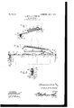
In the accompanying drawings, forming a part of this specification, Figure 1 is a perspective view of a brick-carrier constructed in accordance with my invention. Fig. 2 is a side elevation, partly in section, showing the manner of gripping the bricks. Fig. 3 is an end view of Fig. 2.
Similar numerals of reference indicate corresponding parts in all the figures of the drawings.
The improved device comprises a relatively stationary clamping member 5 and a movable clamping member 6, the latter being provided at one end thereof with a fixed depending gripping-j aw 7, while its opposite end is bent upwardly to form a curved shoulder 8, which terminates in a longitudinallydisposed operating-handle 9. The curved shoulder 8 en ages a slot or opening 10 in the enlarged hea 11 of the stationary member 5, the slotted portion of said head being bent upwardly beyond the general plane of the stationary member and having the front and rear walls of its slot or opening curved or rounded, as indicated at 12, to thereby permit free pivotal movement of the clamping member 6. Mounted for longitudinal movement in the stationary clamping member is an adjustable gripping-j aw 13, the free end of which is preferably bifurcated, as indicated at 14, and provided with inwardly-extending flanges 15 for engagement with the bricks, blocks, or other articles to be carried.
The jaw 13 is provided with a perforated lug 16, in which is mounted for sliding movement a spring-pressed locking-bolt 17, adapted to engage any one of a series of locking recesses or depressions 17, formed in the lower face of the longitudinal bar constituting the stationary clamping member. One end of the bolt is formed with a laterally-extending lug 18 for engagement with a cam-slot 19 in the perforated lug 16, while the opposite end thereof is provided with an operating-handle 20, there being a coil-spring 21 interposed between the lug 16 and a collar 22, fixed on the bolt, so that by simply turning the bolt in a horizontal plane said bolt will be withdrawn from the locking-recesses to permit the adjustment of the gripping-j aw, and when said handle is released the bolt will be retracted by the action of the coil-spring. Rigidly secured to the upper face of the longitudinal bar, constituting the stationary clamping member and supported in spaced relation thereto by means of attaching arms or fingers 22, is an auxiliary handle 23, the free end of which is bent upwardly, as indicated at 24, for engagement with the adjacent downwardly-curved end 25 of the handle 9 of the movable clamping member 6.
The tevminal curved portions 24 and 25 serve to limit the downward movement of the operating-handle 9 when the main and auxiliary handles are drawn together preparatory to gripping the bricks to be transported, so that the two gripping-jaws will be maintained in parallel relation to each other as clearly shown in Fig. 1 of the drawings, and in which position the jaw 7 may be readily introduced between the adjacent faces of ithedbricks or blocks in the act of receiving a oa In operation a number of bricks are arranged side by side, as shown in dotted lines in Fig. 2 of the drawings, and the movable gripping-jaw 13, adjusted longitudinally of the stationary member to correspond to the number of bricks it is desired to carry. The operator then grasps the main and auxiliary levers and draws the two together, which causes the fixed gripping-jaws to assume a vertical position, and in which position said jaw is introduced between the adjacent faces of the bricks, as before stated. By now re leasing the auxiliary lever and exerting an upward lift on the main lever the movable clamping member will be tilted and the gripping-jaw brought into engagement with the two end bricks of the row, thereby permitting the several bricks to be conveniently transported from place to place. To release the bricks, it is only necessary to place the same on the floor or other support and grasp the auxiliary handle, when the bricks will be released and the device be in position to receive another load.
From the foregoing description it will be seen that there is provided an extremely simple and durable device admirably adapted for the attainments of the ends in view.
Having thus described the invention, what is claimed is 1. A device of the class described comprising a stationary and a relatively movable clamping member, and a detachable grippingjaw mounted for longitudinal adjustment on said stationary member.
2. A device of the class described comprising a stationary and a relatively movable clamping member, a detachable grippingjaw mounted for longitudinal adjustment on said stationary member, and means for locking the gripping-j aw in adjusted position.
3. A device of the class described comprising a stationary and a relatively movable clamping member, and a handle carried by the stationary member for cooperation with the movable member in receiving and releasing the load.
4. A device of the class described comprising a stationary clamping member provided with a series of locking-recesses, a movable clamping member pivotally associated therewith, an adjustable gripping-j aw mounted for longitudinal movement in the stationary member, and a locking-bolt carried by the gripping-jaw for engagement with said reeesses.
5. A device of the class described comprising a stationary clamping member provided with a plurality of locking-recesses, a relatively movable clamping member pivotally supported on said stationary member and provided with a fixed terminal gripping-j aw, an adjustable gripping-j aw mounted for longitudinal movement on the stationary member,.a perforated lug secured to said adjustable grippingjaw and having a cam-slot formed in the walls thereof, a spring-pressed bolt slidably mounted in the perforated lug and adapted to engage the locking-recesses in said stationary member, and means for operating said bolt.
6. A device of the class described comprising a stationary clamping member having one end thereof bent upwardly and provided with a terminal slot, a relatively movable clamping member pivotally supported in said slot, and an adjustable gripping-j aw mounted for longitudinal movement on the stationary member.
7. A device of the class described comprising a stationary clamping member provided with a terminal upwardly-bent head having a slot or recess formed therein, the walls of which are curved or rounded, and a relatively movable clamping member provided with an intermediate curved shoulder for engagement with the walls of said slot.
8. A device of the class described comprising a stationary clamping member, a relatively movable clamping member pivotally mounted thereon, and having. one end thereof extended to form a longitudinally-disposed operating-handle, and an auxiliary handle secured to and spaced from the stationary member and adapted to engage the main handle for limiting the downward movement of the latter.
9. A device of the class described comprising a stationary clamping member, a relatively movable clamping member pivotally mounted thereon and provided with a longitudinally-disposed, handle the end of which is bent downwardly, and an auxiliary handle secured to and spaced from the stationary member and provided with an upturned terminal for engagement with the free end of the main handle for limiting the downward movement of the latter.
In testimony that we claim the foregoing as our own we have hereto affixed our signatures in the presence of two witnesses.
RASMUS SKOV. JOHN FORBERG.
Witnesses:
J. E. FoDNEss, O. E. FoDNEss.
Priority Applications (1)
| Application Number | Priority Date | Filing Date | Title |
|---|---|---|---|
| US26266105A US809146A (en) | 1905-05-27 | 1905-05-27 | Brick-tongs. |
Applications Claiming Priority (1)
| Application Number | Priority Date | Filing Date | Title |
|---|---|---|---|
| US26266105A US809146A (en) | 1905-05-27 | 1905-05-27 | Brick-tongs. |
Publications (1)
| Publication Number | Publication Date |
|---|---|
| US809146A true US809146A (en) | 1906-01-02 |
Family
ID=2877627
Family Applications (1)
| Application Number | Title | Priority Date | Filing Date |
|---|---|---|---|
| US26266105A Expired - Lifetime US809146A (en) | 1905-05-27 | 1905-05-27 | Brick-tongs. |
Country Status (1)
| Country | Link |
|---|---|
| US (1) | US809146A (en) |
Cited By (4)
| Publication number | Priority date | Publication date | Assignee | Title |
|---|---|---|---|---|
| US3129029A (en) * | 1961-07-10 | 1964-04-14 | Henry G Ruzza | Device for laying bricks |
| US3134573A (en) * | 1964-05-26 | Bizjak | ||
| US3436112A (en) * | 1967-09-29 | 1969-04-01 | Tony A Pasquine | Lifter and carrier |
| USD547152S1 (en) * | 2005-01-11 | 2007-07-24 | Joseph R Anzaldua | Brick gripping device |
-
1905
- 1905-05-27 US US26266105A patent/US809146A/en not_active Expired - Lifetime
Cited By (4)
| Publication number | Priority date | Publication date | Assignee | Title |
|---|---|---|---|---|
| US3134573A (en) * | 1964-05-26 | Bizjak | ||
| US3129029A (en) * | 1961-07-10 | 1964-04-14 | Henry G Ruzza | Device for laying bricks |
| US3436112A (en) * | 1967-09-29 | 1969-04-01 | Tony A Pasquine | Lifter and carrier |
| USD547152S1 (en) * | 2005-01-11 | 2007-07-24 | Joseph R Anzaldua | Brick gripping device |
Similar Documents
| Publication | Publication Date | Title |
|---|---|---|
| US809146A (en) | Brick-tongs. | |
| US1820169A (en) | Pliers and the like | |
| US905010A (en) | Grapple. | |
| US891509A (en) | Blacksmith and machinist tongs. | |
| US682021A (en) | Nail-grab. | |
| US1120735A (en) | Lifter. | |
| US2578072A (en) | Tongs for handling building blocks | |
| US2367889A (en) | Carrying tongs | |
| US800341A (en) | Brick tongs. | |
| US792758A (en) | Quick-acting clamp. | |
| US2793065A (en) | Handling device for sheet material | |
| US747181A (en) | Brick-handling device. | |
| US638378A (en) | Tongs. | |
| US2457646A (en) | Lifting tongs | |
| US669605A (en) | Cam-and-ratchet vise. | |
| US444778A (en) | Amyer | |
| US370447A (en) | Adjustable wrench | |
| US1320230A (en) | Wrench | |
| US763352A (en) | Hand-tool. | |
| US1345930A (en) | Grip for handling slabs, bars, billets, or other material | |
| US1229408A (en) | Combination-clamp. | |
| US1124806A (en) | Tie-tongs. | |
| US1730619A (en) | Drill rod clamp | |
| US1269683A (en) | Bolt-puller. | |
| US1219979A (en) | Battery-tongs. |