US8091396B2 - Method for forming an end portion of a cylindrical workpiece - Google Patents
Method for forming an end portion of a cylindrical workpiece Download PDFInfo
- Publication number
- US8091396B2 US8091396B2 US12/379,240 US37924009A US8091396B2 US 8091396 B2 US8091396 B2 US 8091396B2 US 37924009 A US37924009 A US 37924009A US 8091396 B2 US8091396 B2 US 8091396B2
- Authority
- US
- United States
- Prior art keywords
- cylindrical workpiece
- end portion
- relative motion
- roller
- cylindrical
- Prior art date
- Legal status (The legal status is an assumption and is not a legal conclusion. Google has not performed a legal analysis and makes no representation as to the accuracy of the status listed.)
- Expired - Fee Related, expires
Links
- 238000000034 method Methods 0.000 title claims abstract description 46
- 230000033001 locomotion Effects 0.000 claims abstract description 93
- 230000002093 peripheral effect Effects 0.000 claims abstract description 23
- 238000009987 spinning Methods 0.000 claims description 52
- 230000007246 mechanism Effects 0.000 description 8
- 125000006850 spacer group Chemical group 0.000 description 4
- 238000010586 diagram Methods 0.000 description 3
- 239000011521 glass Substances 0.000 description 2
- QVGXLLKOCUKJST-UHFFFAOYSA-N atomic oxygen Chemical compound [O] QVGXLLKOCUKJST-UHFFFAOYSA-N 0.000 description 1
- 230000003197 catalytic effect Effects 0.000 description 1
- 238000005520 cutting process Methods 0.000 description 1
- 238000006073 displacement reaction Methods 0.000 description 1
- 238000005242 forging Methods 0.000 description 1
- 239000000446 fuel Substances 0.000 description 1
- 230000006870 function Effects 0.000 description 1
- 239000012212 insulator Substances 0.000 description 1
- 229910052760 oxygen Inorganic materials 0.000 description 1
- 239000001301 oxygen Substances 0.000 description 1
- 230000004044 response Effects 0.000 description 1
- 229910001220 stainless steel Inorganic materials 0.000 description 1
- 239000010935 stainless steel Substances 0.000 description 1
Images


Classifications
-
- B—PERFORMING OPERATIONS; TRANSPORTING
- B21—MECHANICAL METAL-WORKING WITHOUT ESSENTIALLY REMOVING MATERIAL; PUNCHING METAL
- B21D—WORKING OR PROCESSING OF SHEET METAL OR METAL TUBES, RODS OR PROFILES WITHOUT ESSENTIALLY REMOVING MATERIAL; PUNCHING METAL
- B21D22/00—Shaping without cutting, by stamping, spinning, or deep-drawing
- B21D22/14—Spinning
- B21D22/18—Spinning using tools guided to produce the required profile
-
- B—PERFORMING OPERATIONS; TRANSPORTING
- B21—MECHANICAL METAL-WORKING WITHOUT ESSENTIALLY REMOVING MATERIAL; PUNCHING METAL
- B21D—WORKING OR PROCESSING OF SHEET METAL OR METAL TUBES, RODS OR PROFILES WITHOUT ESSENTIALLY REMOVING MATERIAL; PUNCHING METAL
- B21D41/00—Application of procedures in order to alter the diameter of tube ends
- B21D41/04—Reducing; Closing
Definitions
- the present invention relates to a method for forming an end portion of a cylindrical workpiece, particularly the method for forming the end portion of the cylindrical workpiece by a spinning process, to form a part of deformed cross section with non-rotation symmetry on the end portion of the cylindrical workpiece, for example.
- Japanese Patent Laid-open Publication Nos. 2001-286955 and 2007-014983 disclose a spinning process for reducing a diameter of an end portion of a tube having an oval cross section to provide a circular cross section, or a spinning process for reducing a diameter of an end portion of a pipe having a circular cross section to provide a non axially symmetrical shape such as an oval or polygon.
- the end portion of the metallic tubular member may have to be formed into the one having a non circular cross section, or formed with a recess at a portion to be possibly interfered with the neighboring parts, to provide a deformed cross section.
- it can be formed into the one having the non circular cross section according to the aforementioned Japanese Patent Laid-open Publication Nos. 2001-286955 and 2007-014983.
- the roller is to be revolved along a revolutionary locus with rotation symmetric having a center, such as a circle, oval, elongated circle, or the like, it can not be formed into the one having a non-rotation symmetric cross section.
- the plate member can be formed into the hut shape having the deformed cross section.
- those methods can not be applied to the cylindrical workpiece as they are.
- they can not employ a sequential process, but they employ a single locus process, which is different from the spinning process as disclosed in the aforementioned prior publications, they can not be used for the spinning process applied to the end portion of the cylindrical workpiece.
- a method for forming an end portion of a cylindrical workpiece by a spinning process comprises steps of performing a first relative motion of the roller against the cylindrical workpiece toward one open end thereof, performing a second relative motion of the roller against at least a part of outer peripheral surface of the end portion of the cylindrical workpiece toward the inside of the cylindrical workpiece, while the roller is rotated relative to the cylindrical workpiece by one rotation, in such a state as being held to be in contact with the end portion of the cylindrical workpiece, in a plane which is perpendicular to the moving direction of the first relative motion, and which includes a position where the roller contacts the outer peripheral surface of the end portion of the cylindrical workpiece, performing a rotational motion of the roller relatively rotating around the cylindrical workpiece, performing the second relative motion, with the roller being held to be in contact with the outer peripheral surface of the
- a motion cycle including the first relative motion, second relative motion and rotational motion is repeated by a plurality of cycles, so as to form a part of deformed cross section with non-rotation symmetry on the end portion of the cylindrical workpiece.
- the above contacting position may be set to a predetermined position for starting the process, or may be shifted toward one open end of the cylindrical workpiece sequentially according to progress of driving cycles.
- a first moving amount and a second moving amount may be provided on the basis of a difference between a configuration of the cylindrical workpiece to be applied with the spinning process and a target configuration of the cylindrical workpiece with the spinning process applied thereto, to perform the first relative motion and the second relative motion according to the first moving amount and the second moving amount, respectively.
- a relative moving locus of the roller against the cylindrical workpiece may be provided on the basis of a difference between a configuration of the cylindrical workpiece to be applied with the spinning process and a target configuration of the cylindrical workpiece with the spinning process applied thereto, to perform the first relative motion, second relative motion and rotational motion along the relative moving locus.
- the cylindrical workpiece to be applied with the spinning process may include a cylindrical portion and a reduced diameter end portion with at least one end portion of the cylindrical portion being reduced in diameter, and the reduced diameter end portion may include the end portion of the cylindrical workpiece to be processed, and the open end surface of the reduced diameter end portion corresponds to the one open end of the end portion of the cylindrical workpiece, to provide the contacting position on the reduced diameter end portion.
- FIG. 1 is a perspective view showing a method for forming an end portion of a cylindrical workpiece according to an embodiment of the present invention
- FIG. 2 is a schematic diagram showing an apparatus for forming an end portion of a cylindrical workpiece according to an embodiment of the present invention
- FIG. 3 illustrates a front view and a side view of a part of a practical apparatus for use in an embodiment of the present invention
- FIG. 4 is a flowchart showing an example of forming an end portion of a cylindrical workpiece according to an embodiment of the present invention
- FIG. 5 is a process diagram showing an example of process for forming an end portion of a cylindrical workpiece according to an embodiment of the present invention
- FIG. 6 is a side view of another example of an end portion of a cylindrical workpiece formed according to an embodiment of the present invention.
- FIG. 7 is a side view of a further example of an end portion of a cylindrical workpiece formed according to an embodiment of the present invention.
- FIG. 8 is a cross sectional view sectioned along X-X line in FIG. 7 .
- FIG. 9 is a front view of an open end portion as show in FIG. 7 .
- FIG. 10 is a side view of a further example of an end portion of a cylindrical workpiece formed according to an embodiment of the present invention.
- FIG. 11 is a process diagram showing another example for forming an end portion of a cylindrical workpiece according to an embodiment of the present invention.
- FIG. 1 shows a perspective view to explain the method for forming a part of deformed cross section with non-rotation symmetry on the end portion of the cylindrical workpiece.
- the final products of the present embodiment are used for a muffler of an automobile, diesel particulate filter, purifying filter, intake or exhaust parts for use in a fuel cell, or other various pressure containers.
- the cylindrical workpiece to be processed is a stainless steel tube, other metallic tubes may be employed.
- an embodiment of the method for forming an end portion of a cylindrical workpiece 1 is achieved by performing a first relative motion (D 1 ) of a roller 2 against the cylindrical workpiece 1 toward its one open end (rightward in FIG. 1 ), and performing a second relative motion (D 2 ) of the roller 2 against at least a part of outer peripheral surface of the end portion of the cylindrical workpiece 1 , e.g., parts indicated by broken lines in FIG.
- a part of deformed cross section with non-rotation symmetry e.g., the part indicated by “ 12 p ” in FIG. 6 , is formed on the end portion of the cylindrical workpiece 1 .
- a moving locus of the roller 2 becomes a closed loop locus with non-rotation symmetry.
- the locus shall be the one having no central point, such as n-th B-Spline curve, Bezier curve, NURBS (Non-Uniform Rational B-Spline) interpolation curve, or the like.
- the contacting position may be set to be a predetermined starting position of the process, or it may be set to be shifted sequentially toward the one open end of the cylindrical workpiece 1 in response to repetition of driving cycles, the latter of which has been employed in the present embodiment as shown in FIG. 1 .
- FIG. 2 there is schematically illustrated an apparatus for use in the embodiment as described above, and devices as shown in FIG. 3 are used, for example.
- a first relative motion device M 1 is provided for performing the first relative motion (D 1 in FIG. 1 ) of the roller 2 against the cylindrical workpiece 1 toward its one open end
- a second relative motion device M 2 is provided for performing the second relative motion (D 2 in FIG.
- a rotational motion device M 3 is provided for performing the rotational motion (R in FIG.
- a controlling device M 4 performs the first relative motion from the contacting position up to the position exceeding the one open end of the cylindrical workpiece 1 , while repeating the second relative motion by the device M 2 and the rotational motion by the device M 3 , and repeats the motion cycle including the first relative motion, second relative motion and rotational motion by a plurality of cycles (C 1 , C 2 , C 3 and so on).
- the cylindrical workpiece 1 to be applied with the spinning process has a cylindrical portion 11 and a reduced diameter end portion 12 , which was reduced in diameter of at least its one end portion, and the contacting position is set on the reduced diameter end portion 12 , as shown in FIGS. 1 and 2 .
- a target configuration as shown by a broken line in FIG. 1 , and shown by a solid line in FIG.
- the first moving amount by the first relative motion e.g., moving distance gradually reduced from the dimensional difference d 1 according to progress of passes (cycles) C 1 , C 2 , C 3 and so on
- the second moving amount by the second relative motion e.g., moving distance of one third of the dimensional difference d 2 , are provided, so as to perform the first relative motion and the second relative motion according to the first moving amount and the second moving amount, respectively.
- the relative moving locus (not shown) of the roller 2 against the cylindrical workpiece 1 may be provided, so as to perform the first relative motion, second relative motion and rotational motion along the relative moving locus.
- the roller 2 will move by the second moving amount (1 ⁇ 3 of d 2 ), which corresponds to one driving cycle, while the roller 2 rotates one rotation from the contacting position in such a state as being held to be in contact with the end portion of the cylindrical workpiece 1 . Therefore, the rotational amount around the cylindrical workpiece 1 corresponds to its one rotation resulted from the one driving cycle.
- FIG. 3 shows a NC (numerical control) spinning apparatus, as a practical embodiment of the apparatus as shown in FIG. 2 , which is provided with a driving mechanism 31 served as the first relative motion device M 1 , a driving mechanism 32 served as the second relative motion device M 2 and rotational motion device M 3 for driving the three rollers 21 , 22 and 23 , and a controller 100 served as the controlling device M 4 .
- the controller 100 is provided with a microprocessor, memory, input interface and output interface (not shown), from which the control signals are fed into the driving mechanisms 31 and 32 to perform the numerical control (NC).
- the references “S” and so on as indicated in FIG. 3 correspond to the references as indicated in FIGS. 1 and 2 .
- a so-called workpiece fixed type (non-rotating type) has been employed.
- a workpiece rotating type (non-revolving rollers type) may be employed, or both of them may be combined.
- a control circuit may be provided for each driving mechanism to perform a predetermined individual control, respectively.
- the rollers may not be limited to three, and may be disposed separately on each perpendicular plane for a plurality of cycles.
- the rollers 21 , 22 and 23 are driven to move toward one open end of the cylindrical workpiece 1 (leftward in FIG. 3( a )). And, by means of the driving mechanism 32 , the rollers 21 , 22 and 23 are driven to move toward the inside of the cylindrical workpiece 1 , so as to be close to or remote from a part of outer peripheral surface of the end portion of the cylindrical workpiece 1 , e.g., parts except for a convex part 12 p as shown in FIG.
- the aforementioned first and second moving amount for the relative motion between the cylindrical workpiece 1 and the rollers 21 , 22 and 23 may be provided by a moving amount from a reference position, which is set by the intersection point of a moving axis (not shown) of the cylindrical workpiece 1 and the perpendicular plane (S), or provided by a displacement from an absolute reference position, which is set in a three-dimensional space.
- the motion of the cylindrical workpiece 1 driven by the driving mechanism 31 toward its one open end is performed from the contacting position up to the position exceeding its open end, and these driving cycles are repeated by a plurality of cycles (C 1 , C 2 , C 3 and so on).
- FIG. 4 is a flowchart showing an example of the driving control by the controller 100 .
- the first moving amount and the second moving amount are provided on the basis of the difference between the configuration of the cylindrical workpiece 1 to be provided with the spinning process and the target configuration of the cylindrical workpiece 1 with the spinning process applied thereto (d 1 and d 2 ) at Step 102 .
- the driving mechanisms 31 and 32 are driven at Step 103 , to perform the spinning process against the aforementioned part of the cylindrical workpiece 1 .
- N predetermined processing cycle
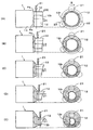
- FIG. 5 shows an example of process for reducing the one end portion of the cylindrical workpiece 1 by the aforementioned spinning process, to form the reduced diameter end portion 12 to be integral with the cylindrical portion 11 , and form a concave portion 12 r at its side surface.
- (A)-(E) show a series of processes (spinning cycles), as an example of a sequential spinning process, wherein each target configuration of a portion to be processed is provided in each cycle, and processed to be gradually close to a desired configuration.
- the rollers 21 , 22 and 23 are driven to be close to and remote from the inside of the cylindrical workpiece 1 along the whole periphery of the end portion of the cylindrical workpiece 1 , i.e., the whole part thereof to constitute “at least a part” of the end portion, while the rollers 21 , 22 and 23 performs one rotation relative to the cylindrical workpiece 1 in such a state as being held to be in contact with each other from the contacting position (Pa), where the rollers 21 , 22 and 23 contact the outer peripheral surface of the end portion of the cylindrical workpiece 1 , in the perpendicular plane (Sa) including the contacting position (Pa), to provide the second motion (D 2 ).
- the rollers 21 , 22 and 23 are driven to move largely toward the inside of the end portion of the cylindrical workpiece 1 , comparing with other outer peripheral surface portions.
- the motion of the cylindrical workpiece 1 toward its open end i.e., the first motion (D 1 ) is performed up to the position exceeding its one open end.
- the rollers 21 , 22 and 23 return to a contacting position (Pb), or may be set to return to the contacting position (Pa).
- the rollers 21 , 22 and 23 are driven to be close to and remote from the inside of the cylindrical workpiece 1 along the whole periphery of the end portion of the cylindrical workpiece 1 , while the rollers 21 , 22 and 23 performs one rotation relative to the cylindrical workpiece 1 , in such a state as being held to be in contact with each other, from the contacting position (Pb), where the rollers 21 , 22 and 23 contact the outer peripheral surface of the end portion of the cylindrical workpiece 1 , in the perpendicular plane including the contacting position (Pb).
- the process at each step of (C)-(E) is performed in the same manner as described above.
- the reduced diameter end portion 12 is formed to be coaxial with the cylindrical portion 11 at the steps of (A) and (B), whereas the reduced diameter end portion 12 is formed to be offset against the cylindrical portion 11 at the steps of (C)-(E).
- the reduced diameter end portion 12 may be formed in an oblique or skewed relationships with the cylindrical portion 11 .
- the reduced diameter end portion 12 can be formed in any one of an offset, oblique or skewed relationships with the cylindrical portion 11 .
- the convex portion 12 p as shown in FIG. 1 and concave portion 12 r as shown in FIG. 5 can be formed at a desired position of the reduced diameter end portion 12 at the same time as the process for reducing its diameter.
- the open end portion (tip end portion) of the reduced diameter end portion 12 may be formed to provide a circular cross section without forming the convex portion 12 p and concave portion 12 r at the step (E), so as to be easily connected to another part, so that a connecting portion having a circular cross section can be formed in a series of steps of the spinning process.
- the tip end portion of the reduced diameter end portion 12 will be cut off after the step (E), to form a circular end surface.
- FIGS. 6-9 show another example processed to the end portion of the cylindrical workpiece 1
- FIGS. 6 and 7 show a step for forming the convex portion 12 p on the end portion of the cylindrical workpiece 1 . It is formed into the one having a rotation symmetric cross section of a circle or elongated circle up to a contacting position (Px), which is the starting point for forming the convex portion 12 p , and from which the second relative motion (D 2 ) and rotational motion (R) are performed in such a state that the roller 21 and so on are in contact with the outer peripheral surface of the reduced diameter end portion 12 , in a plane (Sx) perpendicular to the moving direction of the first relative motion (D 1 ), in the same manner as the aforementioned embodiment, whereby the deformed cross section part having the convex portion 12 p is formed at a part of the cylindrical workpiece 1 toward its one open end.
- Px contacting position
- D 2 second relative motion
- R rotational motion
- FIG. 6 a two-dot chain line as indicated inside of a tapered surface shows its configuration formed into the one having a shape of hour glass, which is to be a target for the process in FIG. 7 .
- a cylindrical open end portion 12 e having an axis ⁇ oblique to the central axis (same as the direction of D 1 ) of the cylindrical portion 11 is formed.
- FIGS. 8 and 9 show a cross section as viewed from X-X and the end surface of the reduced diameter end portion 12 e , respectively, from which the convex portion 12 p extends in the radial direction outside of the cylindrical tip end portion.
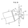
- FIG. 10 shows a further example of forming process to the one end portion of the cylindrical workpiece 1 , wherein after the reduced diameter end portion 12 is formed into the one having the rotation symmetric cross section of the circle or elongated circle, the direction of relative motion of the rollers 21 and etc. against the cylindrical workpiece 1 , i.e., the direction of the first relative motion (D 1 ) is changed to be a different direction, at a contacting position (Py) served as the starting point for the process to the convex portion 12 p , and therefore a plane (Sy) perpendicular to it is changed to be different from the plane (Sx) as shown in FIG. 6 , and the spinning process is performed in the same manner as described above.
- the direction of relative motion of the rollers 21 and etc. against the cylindrical workpiece 1 i.e., the direction of the first relative motion (D 1 ) is changed to be a different direction, at a contacting position (Py) served as the starting point for the process to the convex portion
- the deformed cross section part having the convex portion 12 p is formed at a part of the cylindrical workpiece 1 from the contacting position (Py) toward its one open end.
- a cylindrical open end portion 12 f having an axis ⁇ oblique to the central axis ( ⁇ in FIG. 10 ) of the cylindrical portion 11 is formed.
- the open end portion 12 f is formed with its tip end portion of higher circularity, comparing with the tip end portion of the open end portion 12 e formed by the forming process as shown in FIGS. 6-9
- FIG. 11 shows its example, wherein (A) employs the co-axial spinning process, (B) and (C) employ the offset spinning process, and wherein, against the cylindrical workpiece 1 formed by (C), the rollers 21 and so on are driven along a locus of closed loop with non-rotation symmetry at (D).
- the convex portion 12 p made on the reduced diameter end portion 12 as described above is formed with its tip end surface, which is made into a planar surface, and which is used as a base for a bracket or sensor (not shown).
- a planar portion is required for mounting an oxygen sensor, temperature sensor, various brackets, heat insulator or the like (not shown).
- a separate spacer has been attached to the part formed by the spinning process. This spacer is a metallic member made by a forging process or cutting process, and called as a base block.
- the spacer capable of being connected to a surface of 3-dimension, and also the spacer is required to be welded to the processed portion by the spinning process.
- the convex portion 12 p can be made integrally on the reduced diameter end portion 12 by the sequential spinning process as described before, whereby a large cost down can be achieved.
- the cross section of the end portion of the cylindrical workpiece 1 to be applied with the spinning process is not limited to the circular cross section, but it can be formed into the one having various shapes of oval, elongated circle (racetrack) or the like.
- the cylindrical portion 11 of the workpiece 1 is not limited to the circle, oval, elongated circle or the like, and it can be formed into the one with various shapes of approximately trapezoid, triangle, quadrangle or the like.
- any of the offset, oblique and skewed spinning processes can be combined, an effective necking process can be provided.
Landscapes
- Engineering & Computer Science (AREA)
- Mechanical Engineering (AREA)
- Shaping Metal By Deep-Drawing, Or The Like (AREA)
Abstract
Description
Claims (5)
Applications Claiming Priority (2)
| Application Number | Priority Date | Filing Date | Title |
|---|---|---|---|
| JP2008037877A JP5495496B2 (en) | 2008-02-19 | 2008-02-19 | Cylindrical workpiece end machining method and apparatus |
| JP2008-037877 | 2008-02-19 |
Publications (2)
| Publication Number | Publication Date |
|---|---|
| US20090205386A1 US20090205386A1 (en) | 2009-08-20 |
| US8091396B2 true US8091396B2 (en) | 2012-01-10 |
Family
ID=40599945
Family Applications (1)
| Application Number | Title | Priority Date | Filing Date |
|---|---|---|---|
| US12/379,240 Expired - Fee Related US8091396B2 (en) | 2008-02-19 | 2009-02-17 | Method for forming an end portion of a cylindrical workpiece |
Country Status (4)
| Country | Link |
|---|---|
| US (1) | US8091396B2 (en) |
| EP (1) | EP2092993A3 (en) |
| JP (1) | JP5495496B2 (en) |
| CN (1) | CN101513660B (en) |
Cited By (1)
| Publication number | Priority date | Publication date | Assignee | Title |
|---|---|---|---|---|
| US20160052036A1 (en) * | 2013-04-03 | 2016-02-25 | Toyota Jidosha Kabushiki Kaisha | Spinning method and spinning apparatus |
Families Citing this family (12)
| Publication number | Priority date | Publication date | Assignee | Title |
|---|---|---|---|---|
| US8381823B2 (en) * | 2006-02-08 | 2013-02-26 | Pilot Drilling Control Limited | Downhole tubular connector |
| JP5604139B2 (en) * | 2010-03-05 | 2014-10-08 | 三恵技研工業株式会社 | Manufacturing method of purification equipment for automobile |
| JP5339540B2 (en) * | 2010-12-01 | 2013-11-13 | 日本発條株式会社 | Hollow coil spring and manufacturing method thereof |
| WO2013097272A1 (en) * | 2011-12-30 | 2013-07-04 | Hu Delin | Liquid tank, and apparatus and method for machining same |
| CN102513472B (en) * | 2012-01-09 | 2014-08-13 | 广东骏驰科技有限公司 | Rotary reducing machining device for engine oil delivery pipe |
| JP5934062B2 (en) * | 2012-08-31 | 2016-06-15 | Jfeスチール株式会社 | Spinning method |
| JP5983461B2 (en) * | 2013-02-22 | 2016-08-31 | トヨタ自動車株式会社 | Polygon tube spinning method and muffler manufacturing method |
| JP6468963B2 (en) * | 2015-07-15 | 2019-02-13 | 株式会社三五 | Method for forming cylindrical body |
| CN107838262B (en) * | 2017-12-25 | 2019-04-23 | 沈阳航空航天大学 | A dieless spinning forming method for non-axisymmetric thin-walled shell parts |
| US12214395B2 (en) * | 2019-09-06 | 2025-02-04 | Sango Co., Ltd. | Extrusion molding method for differential thickness pipe and extrusion molding apparatus for differential thickness pipe |
| DE102019128030B3 (en) * | 2019-10-17 | 2020-10-01 | Winkelmann Powertrain Components GmbH & Co. KG. | Process for the production of a screw foundation for fastening elements in the ground |
| CN112045024B (en) * | 2020-07-02 | 2023-03-31 | 长春理工大学 | Spinning forming method of parts with oval cross sections |
Citations (8)
| Publication number | Priority date | Publication date | Assignee | Title |
|---|---|---|---|---|
| JP2957154B2 (en) | 1997-11-18 | 1999-10-04 | 株式会社三五 | Pipe end forming method and apparatus |
| JP2957153B2 (en) | 1997-11-11 | 1999-10-04 | 株式会社三五 | Pipe end forming method and apparatus |
| US6018972A (en) * | 1997-11-11 | 2000-02-01 | Sango Co., Ltd | Method and apparatus for forming an end portion of a cylindrical member |
| JP2001286955A (en) | 2000-04-11 | 2001-10-16 | Sakamoto Industry Co Ltd | Pipe forming method and forming apparatus |
| JP3292570B2 (en) | 1993-11-11 | 2002-06-17 | 茂夫 松原 | Plate forming method and forming apparatus |
| WO2005056210A1 (en) | 2003-12-08 | 2005-06-23 | National Institute Of Advanced Industrial Science And Technology | Method and device for spinning process |
| JP3744390B2 (en) | 2001-08-03 | 2006-02-08 | 豊田工機株式会社 | Processing equipment |
| JP2007014983A (en) | 2005-07-07 | 2007-01-25 | National Institute Of Advanced Industrial & Technology | Pipe forming method and pipe forming apparatus |
Family Cites Families (4)
| Publication number | Priority date | Publication date | Assignee | Title |
|---|---|---|---|---|
| NL1017010C2 (en) * | 2000-12-29 | 2002-07-02 | Johan Massue | Method and device for deforming a hollow workpiece. |
| JP3769612B2 (en) * | 2001-12-13 | 2006-04-26 | 独立行政法人産業技術総合研究所 | Spinning method |
| JP4436199B2 (en) * | 2004-07-12 | 2010-03-24 | 新日本製鐵株式会社 | Tapered steel pipe manufacturing equipment |
| JP5143338B2 (en) * | 2004-12-27 | 2013-02-13 | 株式会社三五 | Method and apparatus for forming different diameter parts of workpiece |
-
2008
- 2008-02-19 JP JP2008037877A patent/JP5495496B2/en active Active
-
2009
- 2009-02-17 US US12/379,240 patent/US8091396B2/en not_active Expired - Fee Related
- 2009-02-18 EP EP09153107.9A patent/EP2092993A3/en not_active Withdrawn
- 2009-02-19 CN CN2009100082053A patent/CN101513660B/en not_active Expired - Fee Related
Patent Citations (10)
| Publication number | Priority date | Publication date | Assignee | Title |
|---|---|---|---|---|
| JP3292570B2 (en) | 1993-11-11 | 2002-06-17 | 茂夫 松原 | Plate forming method and forming apparatus |
| JP2957153B2 (en) | 1997-11-11 | 1999-10-04 | 株式会社三五 | Pipe end forming method and apparatus |
| US6018972A (en) * | 1997-11-11 | 2000-02-01 | Sango Co., Ltd | Method and apparatus for forming an end portion of a cylindrical member |
| JP2957154B2 (en) | 1997-11-18 | 1999-10-04 | 株式会社三五 | Pipe end forming method and apparatus |
| US6067833A (en) | 1997-11-18 | 2000-05-30 | Sango Co., Ltd. | Method and apparatus for forming an end portion of a cylindrical member |
| JP2001286955A (en) | 2000-04-11 | 2001-10-16 | Sakamoto Industry Co Ltd | Pipe forming method and forming apparatus |
| JP3744390B2 (en) | 2001-08-03 | 2006-02-08 | 豊田工機株式会社 | Processing equipment |
| WO2005056210A1 (en) | 2003-12-08 | 2005-06-23 | National Institute Of Advanced Industrial Science And Technology | Method and device for spinning process |
| US20080022741A1 (en) | 2003-12-08 | 2008-01-31 | Hirohiko Arai | Metal Spinning Method and Apparatus |
| JP2007014983A (en) | 2005-07-07 | 2007-01-25 | National Institute Of Advanced Industrial & Technology | Pipe forming method and pipe forming apparatus |
Cited By (3)
| Publication number | Priority date | Publication date | Assignee | Title |
|---|---|---|---|---|
| US20160052036A1 (en) * | 2013-04-03 | 2016-02-25 | Toyota Jidosha Kabushiki Kaisha | Spinning method and spinning apparatus |
| US10239106B2 (en) * | 2013-04-03 | 2019-03-26 | Toyota Jidosha Kabushiki Kaisha | Spinning method and spinning apparatus |
| US11305327B2 (en) * | 2013-04-03 | 2022-04-19 | Toyota Jidosha Kabushiki Kaisha | Spinning method and spinning apparatus |
Also Published As
| Publication number | Publication date |
|---|---|
| US20090205386A1 (en) | 2009-08-20 |
| CN101513660A (en) | 2009-08-26 |
| JP2009195922A (en) | 2009-09-03 |
| EP2092993A2 (en) | 2009-08-26 |
| EP2092993A3 (en) | 2014-01-08 |
| JP5495496B2 (en) | 2014-05-21 |
| CN101513660B (en) | 2012-02-08 |
Similar Documents
| Publication | Publication Date | Title |
|---|---|---|
| US8091396B2 (en) | Method for forming an end portion of a cylindrical workpiece | |
| US20050257588A1 (en) | Metal spin forming head | |
| JP4647056B2 (en) | Tube forming method and forming apparatus | |
| US7963138B2 (en) | Method and apparatus for forming a changed diameter portion of a workpiece | |
| JP2005297041A (en) | Pipe forming method and pipe forming apparatus | |
| US6212926B1 (en) | Method for spin forming a tube | |
| US20070163118A1 (en) | Exhaust line catalyst or muffler shell for motor vehicle and method of producing one such shell | |
| WO2015087752A1 (en) | Method and device for forming elliptical hollow cylinder | |
| JP2008043959A (en) | Method and apparatus of manufacturing spirally grooved tube | |
| EP2981370B1 (en) | Spinning method and spinning apparatus | |
| JP5958967B2 (en) | Forming method of tubular material | |
| JP7058480B2 (en) | Work method and rotary plastic working equipment | |
| JP5756618B2 (en) | Manufacturing method of purification equipment for automobile | |
| JP2015030028A (en) | Spinning method for automobile exhaust pipe parts | |
| CN117715711A (en) | Apparatus and method for manufacturing oil supply pipe | |
| JP2002066658A (en) | Method and apparatus for manufacturing curved pipes | |
| JP2010099729A (en) | Sequential forming apparatus and its method | |
| CN107442725A (en) | Swaged the control method of folding without swage inside and outside circularity quality and avoiding of plug | |
| JP2003010922A (en) | Pipe end forming method | |
| JP2019030889A5 (en) | ||
| RU2085318C1 (en) | Apparatus for making helical groove on tube blank | |
| JP2003013734A (en) | Component for exhaust system and method of manufacturing the same | |
| JP7433523B2 (en) | Spinning method | |
| JP2002205124A (en) | Method for forming end part of work | |
| RU2840419C1 (en) | Method of expanding welded pipes |
Legal Events
| Date | Code | Title | Description |
|---|---|---|---|
| AS | Assignment |
Owner name: SANGO CO., LTD., JAPAN Free format text: ASSIGNMENT OF ASSIGNORS INTEREST;ASSIGNORS:IRIE, TOHRU;OTA, MASASHI;REEL/FRAME:022305/0012 Effective date: 20090213 |
|
| ZAAA | Notice of allowance and fees due |
Free format text: ORIGINAL CODE: NOA |
|
| ZAAB | Notice of allowance mailed |
Free format text: ORIGINAL CODE: MN/=. |
|
| STCF | Information on status: patent grant |
Free format text: PATENTED CASE |
|
| FPAY | Fee payment |
Year of fee payment: 4 |
|
| FEPP | Fee payment procedure |
Free format text: PAYOR NUMBER ASSIGNED (ORIGINAL EVENT CODE: ASPN); ENTITY STATUS OF PATENT OWNER: LARGE ENTITY |
|
| MAFP | Maintenance fee payment |
Free format text: PAYMENT OF MAINTENANCE FEE, 8TH YEAR, LARGE ENTITY (ORIGINAL EVENT CODE: M1552); ENTITY STATUS OF PATENT OWNER: LARGE ENTITY Year of fee payment: 8 |
|
| FEPP | Fee payment procedure |
Free format text: MAINTENANCE FEE REMINDER MAILED (ORIGINAL EVENT CODE: REM.); ENTITY STATUS OF PATENT OWNER: LARGE ENTITY |
|
| LAPS | Lapse for failure to pay maintenance fees |
Free format text: PATENT EXPIRED FOR FAILURE TO PAY MAINTENANCE FEES (ORIGINAL EVENT CODE: EXP.); ENTITY STATUS OF PATENT OWNER: LARGE ENTITY |
|
| STCH | Information on status: patent discontinuation |
Free format text: PATENT EXPIRED DUE TO NONPAYMENT OF MAINTENANCE FEES UNDER 37 CFR 1.362 |
|
| FP | Lapsed due to failure to pay maintenance fee |
Effective date: 20240110 |