US8091281B1 - Removable louver shutter - Google Patents
Removable louver shutter Download PDFInfo
- Publication number
- US8091281B1 US8091281B1 US10/868,471 US86847104A US8091281B1 US 8091281 B1 US8091281 B1 US 8091281B1 US 86847104 A US86847104 A US 86847104A US 8091281 B1 US8091281 B1 US 8091281B1
- Authority
- US
- United States
- Prior art keywords
- shutter
- louver
- stile
- louvers
- frame
- Prior art date
- Legal status (The legal status is an assumption and is not a legal conclusion. Google has not performed a legal analysis and makes no representation as to the accuracy of the status listed.)
- Expired - Fee Related, expires
Links
- 210000002105 tongue Anatomy 0.000 claims description 16
- 239000000463 material Substances 0.000 description 19
- 239000002023 wood Substances 0.000 description 16
- 238000000034 method Methods 0.000 description 13
- 239000000758 substrate Substances 0.000 description 13
- 238000005553 drilling Methods 0.000 description 11
- 230000008569 process Effects 0.000 description 11
- 238000005520 cutting process Methods 0.000 description 9
- 230000000717 retained effect Effects 0.000 description 9
- 239000011162 core material Substances 0.000 description 7
- 239000011094 fiberboard Substances 0.000 description 7
- 239000003292 glue Substances 0.000 description 7
- 238000004519 manufacturing process Methods 0.000 description 6
- 238000010276 construction Methods 0.000 description 5
- 230000006641 stabilisation Effects 0.000 description 5
- 238000011105 stabilization Methods 0.000 description 5
- 238000004026 adhesive bonding Methods 0.000 description 4
- 230000001419 dependent effect Effects 0.000 description 4
- 239000011888 foil Substances 0.000 description 4
- 238000003475 lamination Methods 0.000 description 4
- 239000000123 paper Substances 0.000 description 4
- 238000012546 transfer Methods 0.000 description 4
- 230000008901 benefit Effects 0.000 description 3
- 238000000576 coating method Methods 0.000 description 3
- 238000007796 conventional method Methods 0.000 description 3
- 238000010030 laminating Methods 0.000 description 3
- 239000004033 plastic Substances 0.000 description 3
- 238000012545 processing Methods 0.000 description 3
- 239000003381 stabilizer Substances 0.000 description 3
- 229910000760 Hardened steel Inorganic materials 0.000 description 2
- 239000003000 extruded plastic Substances 0.000 description 2
- 238000009434 installation Methods 0.000 description 2
- 238000005259 measurement Methods 0.000 description 2
- 238000003801 milling Methods 0.000 description 2
- 241001417523 Plesiopidae Species 0.000 description 1
- 241000219000 Populus Species 0.000 description 1
- 230000004888 barrier function Effects 0.000 description 1
- 238000005336 cracking Methods 0.000 description 1
- 238000007730 finishing process Methods 0.000 description 1
- 230000007246 mechanism Effects 0.000 description 1
- 238000012986 modification Methods 0.000 description 1
- 230000004048 modification Effects 0.000 description 1
- 125000006850 spacer group Chemical group 0.000 description 1
Images


Classifications
-
- E—FIXED CONSTRUCTIONS
- E06—DOORS, WINDOWS, SHUTTERS, OR ROLLER BLINDS IN GENERAL; LADDERS
- E06B—FIXED OR MOVABLE CLOSURES FOR OPENINGS IN BUILDINGS, VEHICLES, FENCES OR LIKE ENCLOSURES IN GENERAL, e.g. DOORS, WINDOWS, BLINDS, GATES
- E06B7/00—Special arrangements or measures in connection with doors or windows
- E06B7/02—Special arrangements or measures in connection with doors or windows for providing ventilation, e.g. through double windows; Arrangement of ventilation roses
- E06B7/08—Louvre doors, windows or grilles
- E06B7/084—Louvre doors, windows or grilles with rotatable lamellae
- E06B7/086—Louvre doors, windows or grilles with rotatable lamellae interconnected for concurrent movement
-
- Y—GENERAL TAGGING OF NEW TECHNOLOGICAL DEVELOPMENTS; GENERAL TAGGING OF CROSS-SECTIONAL TECHNOLOGIES SPANNING OVER SEVERAL SECTIONS OF THE IPC; TECHNICAL SUBJECTS COVERED BY FORMER USPC CROSS-REFERENCE ART COLLECTIONS [XRACs] AND DIGESTS
- Y10—TECHNICAL SUBJECTS COVERED BY FORMER USPC
- Y10T—TECHNICAL SUBJECTS COVERED BY FORMER US CLASSIFICATION
- Y10T29/00—Metal working
- Y10T29/39—Venetian blind assembling
-
- Y—GENERAL TAGGING OF NEW TECHNOLOGICAL DEVELOPMENTS; GENERAL TAGGING OF CROSS-SECTIONAL TECHNOLOGIES SPANNING OVER SEVERAL SECTIONS OF THE IPC; TECHNICAL SUBJECTS COVERED BY FORMER USPC CROSS-REFERENCE ART COLLECTIONS [XRACs] AND DIGESTS
- Y10—TECHNICAL SUBJECTS COVERED BY FORMER USPC
- Y10T—TECHNICAL SUBJECTS COVERED BY FORMER US CLASSIFICATION
- Y10T29/00—Metal working
- Y10T29/49—Method of mechanical manufacture
- Y10T29/49789—Obtaining plural product pieces from unitary workpiece
-
- Y—GENERAL TAGGING OF NEW TECHNOLOGICAL DEVELOPMENTS; GENERAL TAGGING OF CROSS-SECTIONAL TECHNOLOGIES SPANNING OVER SEVERAL SECTIONS OF THE IPC; TECHNICAL SUBJECTS COVERED BY FORMER USPC CROSS-REFERENCE ART COLLECTIONS [XRACs] AND DIGESTS
- Y10—TECHNICAL SUBJECTS COVERED BY FORMER USPC
- Y10T—TECHNICAL SUBJECTS COVERED BY FORMER US CLASSIFICATION
- Y10T29/00—Metal working
- Y10T29/49—Method of mechanical manufacture
- Y10T29/4981—Utilizing transitory attached element or associated separate material
-
- Y—GENERAL TAGGING OF NEW TECHNOLOGICAL DEVELOPMENTS; GENERAL TAGGING OF CROSS-SECTIONAL TECHNOLOGIES SPANNING OVER SEVERAL SECTIONS OF THE IPC; TECHNICAL SUBJECTS COVERED BY FORMER USPC CROSS-REFERENCE ART COLLECTIONS [XRACs] AND DIGESTS
- Y10—TECHNICAL SUBJECTS COVERED BY FORMER USPC
- Y10T—TECHNICAL SUBJECTS COVERED BY FORMER US CLASSIFICATION
- Y10T29/00—Metal working
- Y10T29/49—Method of mechanical manufacture
- Y10T29/49826—Assembling or joining
- Y10T29/4984—Retaining clearance for motion between assembled parts
-
- Y—GENERAL TAGGING OF NEW TECHNOLOGICAL DEVELOPMENTS; GENERAL TAGGING OF CROSS-SECTIONAL TECHNOLOGIES SPANNING OVER SEVERAL SECTIONS OF THE IPC; TECHNICAL SUBJECTS COVERED BY FORMER USPC CROSS-REFERENCE ART COLLECTIONS [XRACs] AND DIGESTS
- Y10—TECHNICAL SUBJECTS COVERED BY FORMER USPC
- Y10T—TECHNICAL SUBJECTS COVERED BY FORMER US CLASSIFICATION
- Y10T29/00—Metal working
- Y10T29/49—Method of mechanical manufacture
- Y10T29/49995—Shaping one-piece blank by removing material
- Y10T29/49996—Successive distinct removal operations
Definitions
- Shutters are a high quality interior window treatment, having a combination of style, functionality and elegance that sets them apart from other window coverings. Shutters provide warmth in the winter and protect from damaging heat and sunlight in the summer. Shutters also provide complete control of view, privacy and light. Conventional shutters are made of an indigenous wood such as popular, oak or ash. The shutter components are typically assembled using doweling, screws and staples. After assembly, the shutters are stained or painted.
- a removable louver shutter comprises a shutter frame defining an opening and a plurality of inserts mounted to the frame proximate to the opening.
- a plurality of end caps are rotatably mounted along the inserts.
- a plurality of generally planar louvers are each removably attached between corresponding pairs of the end caps so as to be disposed within the opening.
- At least one link bar connects the end caps so as to move the louvers between an open position and a closed position.
- the shutter comprises a groove defined along a portion of the frame proximate the opening, and the inserts may be retained within the groove.
- the shutter further comprises a plurality of pin holes defined by, and spaced at regular intervals along, each of the inserts.
- a plurality of stile buttons are disposed one each on the end caps, where each of the stile buttons are retained within corresponding ones of the pin holes.
- the shutter comprises a plurality of flexible flaps disposed on the end caps. The flaps re flexible so as to grip the louvers and deflect for attachment to and detachment from the louvers.
- the shutter further comprises a plurality of link bar holes defined by the link bar.
- a plurality of link bar buttons are disposed on the end caps, and the link bar buttons are retained within corresponding ones of the link bar holes.
- a removable louver shutter comprises a shutter frame and a plurality of flexible louver attachments rotatably mounted within the frame.
- a plurality of generally planar louvers are removably gripped by the attachments and the louvers are attached and detached by deflecting the louver attachments.
- the shutter may further comprise an insert mounted to the frame, and the louver attachments may be rotatably mounted along the insert.
- a groove is defined by the frame and the insert is retained within the groove.
- the shutter further comprises a link bar interconnecting at least a portion of the louver attachments so that rotation of one of the louvers causes a corresponding rotation of multiple ones of the louvers.
- the louvers are individually removable without disconnecting the link bar.
- a further aspect of a removable louver shutter comprises a flexible insert adapted to mount to a shutter frame and a plurality of flexible end caps configured to rotatably mount to the insert.
- the end caps are adapted to removably retain a corresponding plurality of louvers within the shutter frame.
- the insert comprises a shelf and a plurality of legs extending perpendicularly from the shelf. The legs are adapted to fit within a groove defined by the frame, and the shelf is adapted to rest along an inside portion of the frame.
- a plurality of pin holes may be defined by and evenly spaced along the insert.
- the shutter further comprises a plurality of insert buttons, where one of the buttons extends from each of the end caps.
- the buttons are adapted to snap-fit into and be rotatably retained within pin holes defined along the insert.
- the end caps may comprise a cap body and a plurality of side flaps and a plurality of end flaps which extend normal to the body.
- the side flaps are configured to grip faces of the louvers and the end flaps are configured to grip edges of the louvers.
- the flaps deflect for attachment and detachment of ends of the louvers.
- the shutter comprises a link bar interconnecting the end caps so as to move the louvers between open and closed positions.
- the link bar may be disposed at the rear of the shutter and may be adapted to fit between the louvers and the shutter frame.
- a plurality of link bar holes may be defined along the link bar and configured to rotatably attach to the end caps.
- a plurality of link bar buttons may extend from at least a portion of the end caps, and the buttons may be adapted to snap-fit into and be rotatably retained within the link bar holes.
- FIG. 1 is a perspective view of a prefinished, medium density fiberboard (MDF) shutter
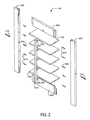
- FIG. 2 is an exploded perspective view of a prefinished MDF shutter
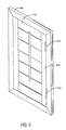
- FIG. 3 is a front perspective view of a prefinished MDF shutter mounted within a window frame
- FIG. 4 is a back perspective view of a finger-jointed, natural wood window frame, such as shown in FIG. 3 ;
- FIGS. 5A-D are end, outside edge, front and inside edge views, respectively, of a partial groove stile
- FIGS. 6A-E are outside edge, perspective, front, and end views of a top spreader, and a perspective view of a bottom spreader, respectively;
- FIGS. 7A-D are leading edge, perspective, top and end views of a louver
- FIGS. 8A-D are end, perspective, front edge and side views of a tilt bar
- FIGS. 9A-B are front-end and back-end perspective views, respectively, of a threaded anchor for louver tension control and frame stabilization
- FIGS. 10A-B are flowcharts of a shutter component prefinishing process and a prefinished shutter assembly process, respectively;
- FIG. 11 is a perspective view of a laminated and cut substrate sheet
- FIG. 12 is a perspective view of a laminated and cut substrate board
- FIG. 13 is a perspective view of a laminated component
- FIGS. 14A-G are end, front, inside edge, perspective, exploded inside edge perspective, exploded outside edge perspective and detailed end views, respectively, of a full groove stile;
- FIGS. 15A-D are end, outside edge, front and inside edge views, respectively, of a full groove stile base
- FIGS. 16A-D are front, side, end and detailed end views, respectively, of a groove insert
- FIGS. 17A-B are exploded perspective and perspective views, respectively, of a capped louver
- FIGS. 18A-C are inside face perspective, outside face perspective, and alternative embodiment outside face perspective views, respectively, of a louver end cap.
- FIG. 19 is an exploded perspective view of an alternative embodiment prefinished MDF shutter.
- FIG. 1 illustrates an assembled, prefinished, medium density fiberboard (MDF) shutter 100 .
- the shutter 100 is installable within a window opening and operable to control the amount of light entering a building interior and to maintain the privacy of the building occupants, in a manner that is well known in the art.
- the shutter 100 has stiles 500 , spreaders 600 , louvers 700 and a tilt bar 800 .
- the stiles 500 are fixedly attached to the spreaders 600 so as to form a shutter frame 102 having a generally rectangular opening 104 .
- shutter embodiments having non-rectangular openings to accommodate windows of various sizes and shapes can be constructed using the materials and processes described herein.
- the louvers 700 are rotatably mounted to the stiles 500 within the frame 102 .
- the tilt bar 800 is linked to the leading edges of the louvers 700 and operable up and down so as to rotate the louvers to various positions.
- the shutter 100 has a closed position (shown) with the tilt bar 800 in a fully up position and the louvers 700 overlapping along the edges so as to block light from passing through the opening 102 .
- the shutter 100 also has various open positions (not shown) with the tilt bar 800 positioned away from the fully up position and the louvers 700 rotated away from the plane of the opening 104 so as to allow light to pass.
- FIG. 2 shows a shutter 100 in exploded perspective view, further illustrating the various shutter components.
- a pair of stiles 500 , a top spreader 600 and a bottom spreader 650 are mutually attached using tongue and groove construction to form a shutter frame 102 ( FIG. 1 ).
- the stiles 500 are described in detail with respect to FIGS. 5A-D , below.
- the spreaders 600 , 650 are described in detail with respect to FIGS. 6A-E , below.
- louvers 700 are rotatably mounted to the stiles 500 using standard louver pins 210 , such as Sullivan part #F9020W, which is a 1′′ plastic pin with a 1 ⁇ 8′′ dia. ⁇ 5 ⁇ 8′′ stake portion including a 1/32′′ spacer that is press-fit into a louver 700 and a 1 ⁇ 4′′ dia. ⁇ 3 ⁇ 8′′ cylindrical portion that rotates within a stile 500 .
- standard louver pins 210 such as Sullivan part #F9020W, which is a 1′′ plastic pin with a 1 ⁇ 8′′ dia. ⁇ 5 ⁇ 8′′ stake portion including a 1/32′′ spacer that is press-fit into a louver 700 and a 1 ⁇ 4′′ dia. ⁇ 3 ⁇ 8′′ cylindrical portion that rotates within a stile 500 .
- one or more selected louvers 700 receive an anchor 900 instead of a louver pin 210 .
- Each louver 700 having anchors 900 is rotatably mounted to the stiles 500 with a pair of standard 8-32 ⁇ 2′′ roundhead screws 230 .
- the anchors 900 and screws 230 advantageously function both as an adjustable louver tension control and a frame stabilizer.
- the anchors 900 and the associated tension control and frame stabilization mechanisms are described in detail with respect to FIGS. 9A-B , below.
- the tilt bar 800 is attached to an edge of each of the louvers 700 with an interlocked tilt bar link 240 and louver link 250 , such as a 1′′ ⁇ 1 ⁇ 4′′ ⁇ 1/16′′ dia.
- wire staple and a 3 ⁇ 4′′ ⁇ 1 ⁇ 4′′ ⁇ 1/16′′ dia. wire staple Prefinishing and construction of the shutter components is described in detail with respect to FIG. 10A , below. Assembly of the shutter components is described in detail with respect to FIG. 10B , below.
- FIGS. 3-4 illustrate a window frame 400 .
- FIG. 3 is a front, perspective view illustrating a shutter 100 mounted within a window frame 400 .
- FIG. 4 is a back, perspective view illustrating one embodiment of a prefinished window frame 400 utilizing finger-jointed, natural wood.
- a shutter 100 is attached to a window frame 400 with hinges 310 mounted to the window frame 400 and one of the stiles 500 , allowing the shutter 100 to swing open or closed.
- the window frame 400 has a finger-jointed, natural wood core 410 such as formed from 2′, 3′ or 4′ pieces of poplar.
- the wood core 410 is partially finished with a profile wrap 420 .
- the wrapped sections of the window frame 400 are attached at the corners with screws, nails or staples, as is well-known in the art.
- FIGS. 5A-D illustrate a partial groove stile embodiment 500 .
- a full groove stile embodiment 1400 ( FIGS. 14A-G ) is described with respect to FIGS. 14-16 , below.
- a stile 500 is a generally elongated, planar shutter component having first and second faces 501 , first and second ends 503 , an outside edge 505 and an inside edge 507 .
- a pair of stiles 500 form the sides to an assembled shutter frame 102 ( FIG. 1 ), as described above, and extend vertically when a shutter 100 ( FIG. 1 ) is installed in a conventional window.
- Stiles 500 provide mounts for the shutter louvers 700 ( FIG. 1 ), as described with respect to FIGS. 1-2 , above, and a structure for hinge attachment to a window frame 400 ( FIG. 3 ), as described with respect to FIG. 3 , above.
- a stile 500 is prefinished, having a substrate material with a first laminate applied to the stile faces 501 and a second laminate applied to the stile edges 505 , 507 .
- the core material is medium density fiberboard (MDF)
- the first laminate is a decorative paper, such as US Coatings High Gloss OSS White
- the second laminate is a heat transfer foil, such as Kurtz part #C87046SR. The lamination process is described with respect to FIGS. 10-13 , below.
- a stile 500 has partial grooves 510 extending within each end 503 toward the opposite end 503 along the inside edge 507 .
- the grooves 510 are configured to receive the spreader tongues 610 ( FIGS. 6A-E ).
- a stile 500 has a number of pin holes 530 extending into the stile 500 perpendicularly from the inside edge 507 and spaced at regular intervals along the inside edge 507 .
- the pin holes 530 are configured to receive a louver pin 210 ( FIG. 2 ) for rotatably mounting a louver 700 ( FIG. 2 ), as described with respect to FIGS. 1-2 , above and FIG. 10B , below.
- the stile 500 has one or more tension adjustment holes 550 extending into the stile 500 at a predetermined spacing along the outside edge 505 .
- the adjustment holes 550 are configured to accept a tensioning screw 230 ( FIG. 2 ) threaded into an adjustment hole 550 , out a corresponding pin hole 530 and into an anchor 900 ( FIG. 2 ), so that the head of the screw 230 ( FIG. 2 ) is retained within the stile 500 .
- the stile length is window frame dependent, which is a custom measurement for each installation.
- a stile width i.e. across a face 501
- a stile thickness i.e. across an edge 505 , 507
- a standard wood shutter typically is constructed with 11 ⁇ 4′′ thickness boards for both stiles and spreaders.
- the stile 500 is advantageously constructed of thinner MDF, i.e. in the range of 3 ⁇ 4′′ to 11 ⁇ 4′′, providing a shutter with comparable strength and less cost due to less material used.
- a groove 510 is 1 ⁇ 4′′ ⁇ 3 ⁇ 4′′ and corresponds to a spreader width.
- a pin hole 530 is 1 ⁇ 4′′ dia. ⁇ 3 ⁇ 8′′, and a tension adjustment hole 550 is 3 ⁇ 8′′ dia.
- FIGS. 6A-E illustrate a spreader 600 , 650 .
- a spreader 600 , 650 is a generally planar shutter component having first and second faces 601 , first and second ends 603 , a inside edge 605 and an outside edge 607 .
- a top spreader 600 and a bottom spreader 650 ( FIG. 6E ) form the top and bottom of an assembled shutter frame 102 ( FIG. 1 ), as described above, and extend horizontally when a shutter 100 ( FIG. 1 ) is installed in a conventional window.
- a spreader 600 , 650 has a shaped cutout 620 along the length of the inside edge 605 configured to accommodate a louver edge 705 , 707 ( FIGS. 7A-D ) when the shutter 100 ( FIG.
- a top spreader 600 has a notch 630 in one face 601 at the inside edge 605 generally centered between the ends 603 .
- a bottom spreader 650 is identical to a top spreader 600 except that it does not have the notch 630 ( FIGS. 6B-C ).
- a top spreader 600 is installed in the shutter frame 102 ( FIG. 1 ) with the cutout 620 proximate the tilt bar 800 ( FIG. 1 ).
- the bottom spreader 650 ( FIG. 6E ) is installed in the shutter frame 102 ( FIG. 1 ) with the cutout 620 distal the tilt bar 800 ( FIG. 1 ).
- a spreader 600 , 650 also has tongues 610 extending away from each end 603 . The tongues 610 are configured to insert into the stile grooves 510 ( FIGS. 5A-D ).
- a spreader 600 , 650 is prefinished, having a substrate material with a first laminate applied to the spreader faces 601 and a second laminate applied to the spreader inside edge 605 .
- the substrate material is medium density fiberboard (MDF)
- the first laminate is a decorative paper
- the second laminate is a heat transfer foil, as described with respect to FIGS. 5A-D , above.
- the lamination process is described with respect to FIGS. 10-13 , below.
- the spreader length is window frame dependent, which is a custom measurement for each installation but less than 30′′ as determined by the louver length, as described with respect to FIGS. 7A-D , below.
- a spreader width i.e. across a face 601
- a spreader thickness i.e. across an edge 605 , 607 is 5 ⁇ 8′′.
- a spreader 600 , 650 is advantageously thinner, i.e.
- a spreader 600 , 650 is thinner than a stile 500 ( FIGS. 5A-D ), creating a 1 ⁇ 8′′ step 108 ( FIG. 1 ) that advantageously disguises a stile-spreader seam between these two components.
- a tongue is 1 ⁇ 4′′ ⁇ 3 ⁇ 4′′ and extends most of the spreader width.
- FIGS. 7A-D illustrate a louver 700 , which is a generally planar shutter component having first and second faces 701 , first and second ends 703 , a leading edge 705 and a trailing edge 707 .
- Multiple louvers 700 are rotatably mounted within an assembled shutter frame 102 ( FIG. 1 ) and extend horizontally between stiles 500 ( FIG. 1 ) when a shutter 100 ( FIG. 1 ) is installed in a conventional window.
- a louver 700 has a pin hole 710 generally centered at each end 703 and extending partially into the louver 700 along an axis of rotation.
- the pin hole 710 is configured to accept either a press-fit louver pin 210 ( FIG. 2 ) or a screwed-in anchor 900 ( FIG.
- a louver 700 also has predrilled link holes 720 centered between the ends 703 along the leading edge 705 .
- the link holes 720 are configured to accept a louver link 250 ( FIG. 2 ).
- a louver 700 is constructed of a substrate material with a first laminate applied to the louver faces 701 and a second laminate applied to the louver edges 705 , 707 .
- the second laminate may also be applied to the louver ends 703 .
- the substrate material is MDF
- the first laminate is a decorative paper
- the second laminate is a heat transfer foil, as described with respect to FIGS. 5A-D , above.
- the lamination process is described with respect to FIGS. 10-13 , below.
- the louver length is window frame dependent but less than about 30′′ when using MDF so as to advantageously avoid louver instability and wobble.
- a width, i.e. across a face 701 is 21 ⁇ 2′′, 31 ⁇ 2′′ or 41 ⁇ 2′′
- a louver thickness, i.e. across an edge 705 , 707 is 3 ⁇ 8′′.
- a louver pin hole 710 is 1 ⁇ 8′′ dia. ⁇ 5 ⁇ 8′′ and the link holes 720 are spaced 1 ⁇ 4′′ apart and are 5/64′′ dia. ⁇ 1 ⁇ 2′′.
- FIGS. 8A-D illustrate a tilt bar 800 .
- a tilt bar 800 is an elongated rod having a generally rectangular cross-section with rounded corners on a front edge 810 and square corners on a back edge 820 and sides 830 .
- the tilt bar 800 is constructed of 16′ standard tilt rod natural wood stock, which is milled, sanded and prefinished with a profile wrap, such as used on the wood frame 400 ( FIG. 4 ). The prefinished stock is cut to length, which is window frame dependent.
- the back edge 820 is 1 ⁇ 2′′ and the side edges 830 are 5 ⁇ 8′′.
- FIGS. 9A-B illustrate an anchor 900 .
- the anchor 900 is a generally hollow cylinder having a socket end 901 , a round end 902 , coarse outer threads 910 and fine inner threads 940 .
- the socket end 901 is utilized to drive the anchor 900 into a louver pin hole 710 ( FIGS. 7A-D ), so that the outer threads 910 cut into the pin hole 710 ( FIGS. 7A-D ).
- This, with the addition of glue allows the anchor 900 to firmly grip inside the louver 700 ( FIGS. 7A-D ).
- the fine threads 940 accommodate the threads of the tensioning screw 230 ( FIG. 2 ).
- the anchor 900 has 3 to 12 coarse threads 910 and, in a particularly advantageous embodiment, the number of coarse threads 910 is at least 9 so as to prevent the anchor 900 from stripping from MDF louvers 700 ( FIGS. 7A-D ).
- the anchor 900 and tensioning screw 230 ( FIG. 2 ) advantageously function as both a louver tension control and frame stabilizer. Louver tension control determines the force required for the tilt bar to rotate the louvers. Traditional shutters provide tensioning with screws threaded directly into a selected louver. The tension is adjusted high enough so that the louvers maintain a particular position set with the tilt bar and low enough so that the louvers are easily repositioned. Such screws will quickly strip out of MDF louvers when sufficient operational tension is applied.
- the anchors 900 advantageously prevent the tensioning screw 230 ( FIG. 2 ) from stripping out of a louver 700 ( FIG. 2 ). Further, a shutter frame made of MDF is unstable in that it bows and warps.
- the anchors 900 advantageously allow sufficient tension to be distributed along the stiles 500 ( FIG. 2 ) to reduce bowing and warping.
- the anchors 900 are inserted into one or more selected louvers at a predetermined spacing along the stiles 500 ( FIG. 2 ).
- the anchored louver spacing is no greater than about every 24′′ so as to advantageously provide sufficient and evenly distributed tension on the shutter frame 102 ( FIG. 1 ).
- FIGS. 10A-B illustrate a shutter component prefinishing process and a prefinished shutter assembly process, respectively.
- an initial processing step is selecting a shutter component type 1002 , which includes a stile 500 ( FIG. 2 ), a spreader 600 ( FIG. 2 ) and a louver 700 ( FIG. 2 ), as described above.
- a next step is determining a substrate sheet size 1004 .
- a substrate sheet may comprise multiple, edge-to-edge shutter components that are laminated in bulk and separated by cutting along edge portions, saving manufacturing steps.
- standard 4′ ⁇ 8′ ⁇ 3 ⁇ 8′′ MDF sheets are used for louvers 700 ( FIGS.
- FIG. 11 illustrates sheet lamination and cutting, which yield a laminated board 1150 .
- An substrate 1100 is sandwiched between a first laminate 1110 to form a laminated sheet 1103 .
- a hot roll laminator such as a TB-60 from Black Bros. Co., Mendota, Ill.
- Laminated boards 1150 are then cut from the laminated sheet 1103 at predetermined widths 1120 corresponding to a particular shutter component.
- the predetermined widths 1120 produce boards 1150 that are 1 ⁇ 8′′ wider than the final component width to allow for losses when the edges are milled and sanded, as described with respect to FIG. 12 , below.
- laminated boards 1150 of 25 ⁇ 8′′, 35 ⁇ 8′′ or 45 ⁇ 8′′ widths are cut for 21 ⁇ 2′′, 31 ⁇ 2′′ or 41 ⁇ 2′′ louvers 700 ( FIGS. 7A-D ), respectively.
- additional processing steps include milling, sanding and laminating board edges 1014 and cutting a laminated board into laminated shutter components 1016 , as described in further detail with respect to FIG. 12 .
- a laminated board may comprise multiple, end-to-end shutter components that are laminated along previously cut edges in bulk and then separated by cutting along attached end portions, saving manufacturing steps.
- a laminated board 1150 has edges 1151 ( FIG. 11 ), one or both of which may be milled flat or to a particular shape to form a milled edge 1201 and then sanded accordingly.
- a second laminate 1210 is then applied to one or both milled edges 1201 .
- Prefinished shutter components 1230 are cut from a laminated board 1150 at predetermined lengths 1220 corresponding to the custom measured length for a particular shutter component.
- a cutting grooves at stile ends step 1022 forms the grooves 510 ( FIGS. 5A-D ) used for tongue and groove assembly of the shutter frame 102 ( FIG. 1 ).
- a drilling pin holes step 1024 forms the stile pin holes 530 ( FIG. 5D ) that retain louver pins 210 ( FIG. 2 ) or tensioning screws 230 ( FIG. 2 ), as described above.
- a drilling adjustment hole(s) step 1028 forms the tension adjustment hole(s) 550 ( FIG. 5B ) for inserting and adjusting the tensioning screws 230 ( FIG. 2 ), as described above.
- an additional step applied to a prefinished spreader component is cutting a tongue at the spreader ends 1032 .
- the cutting a tongue step 1032 creates a tongue 610 ( FIGS. 6A-E ) for tongue and groove attachment of spreaders 600 , 650 ( FIG. 2 ) and stiles 500 ( FIG. 2 ), as described with respect to FIG. 10B , below.
- a further step applied to a top spreader 600 is cutting a tilt bar notch 1034 .
- a tilt bar notch 630 FIGS. 6B-C ) is described with respect to FIGS. 6A-E , above. This step is eliminated for a bottom spreader 650 ( FIG. 6E ).
- a drilling pin holes step 1042 forms the louver pin holes 710 ( FIGS. 7B , 7 D) that retain louver pins 210 ( FIG. 2 ) or anchors 900 ( FIG. 2 ), as described above.
- a drilling link holes step 1044 forms the predrilled link holes 720 ( FIGS. 7A-B ) that advantageously allow a louver link 250 ( FIG. 2 ) to be inserted into a louver 700 ( FIGS. 7A-D ) without splitting, as described above and further with respect to FIG. 10B , below.
- An installing anchors step 1048 inserts an anchor 900 ( FIG. 2 ) into the pin holes 710 ( FIGS. 7B , 7 D) of selected louvers 700 ( FIGS. 7A-D ), providing tension control and frame stabilization, as described with respect to FIGS. 9A-B , above.
- a drilling jig (not shown) for pre-drilling the louver link holes 720 can be used.
- the conventional method of attaching the tilt bar to each louver is to use a staple attached to both the tilt bar and the louver, each being placed only 1 ⁇ 4′′ or so out from the respective surfaces.
- the conventional method of staple attachment is to fire staples from a gun in rapid succession, which typically crack or split the louver.
- the louver is then patched and painted over during a post-finishing process.
- a barrier to the use of MDF for shutter construction has been the splitting of the louver when attaching the tilt bar to the louver using this conventional technique.
- a drilling jig is made of a hardened steel plate with guild holes pattered to copy the exact pattern of the staple holes in a stacked pattern of multiple louver units. This jig allows a simple “pre-drill” process followed by hand gluing of the staples into the louvers, as described below.
- a further processing step includes milling, sanding and laminating shutter component ends 1018 , described in further detail with respect to FIG. 13 .
- a prefinished component 1230 has cut ends 1301 with an exposed core 1100 .
- a second laminate 1310 is also applied to these ends 1301 .
- This step is advantageously applied to a louver 700 ( FIGS. 7A-D ) after drilling so as to avoid damage to the finish.
- a louver end may be capped, as described with respect to FIGS. 17-18 , below.
- Shutter assembly includes the steps of installing anchors in selected louvers 1052 , installing louver pins 1054 and positioning the shutter components 1058 .
- an anchor 900 FIGS. 9A-B
- an anchor 900 FIGS. 9A-B
- the glue is then allowed to set for a period of 1 hour.
- louver pins step 1054 ends of the louver pins 210 ( FIG. 2 ) are press-fitted into the non-anchored louver pin holes 710 ( FIG. 7B ) prior to attachment of the stiles 500 ( FIG. 2 ) to the spreaders 600 ( FIG. 2 ).
- stiles 500 ( FIGS. 5A-D ) and spreaders 600 ( FIGS. 6A-E ) are positioned for assembly of a shutter frame 102 ( FIG. 1 ) and louvers 700 ( FIGS. 7A-D ) are positioned between the stiles 500 ( FIGS. 5A-D ), as described with respect to FIG. 2 , above.
- FIG. 10B another assembly step is gluing and clamping a shutter frame around the positioned louver components 1062 .
- Conventional custom shutters are typically constructed with dowels and/or screws attaching the spreaders to the stiles. This convention shutter assembly method would cause MDF material to split.
- the shutter frame assembly step 1062 advantageously utilizes tongue and groove construction for assembly of the stiles 500 ( FIGS. 5A-D ) and spreaders 600 ( FIGS. 6A-E ), which avoids MDF material splitting.
- Spreader tongues 610 FIGS. 6A-E
- each louver 700 ( FIGS. 7A-D ) having anchors 900 ( FIGS. 9A-B ) is attached to the stiles 500 ( FIGS. 5A-D ) with tensioning screws 230 ( FIG. 2 ) inserted into the stile adjustment holes 550 ( FIG. 5B ), pushed through the corresponding stile pin holes 530 ( FIG. 5D ) and threaded into corresponding anchors 900 ( FIGS. 9A-B ).
- each louver 700 ( FIGS. 7A-D ) is mounted between stiles 500 ( FIGS. 5A-D ) with louver pins 210 ( FIG.
- louvers 700 ( FIGS. 7A-D ) are instead mounted with tensioning screws 230 ( FIG. 2 ) threaded into and retained by anchors 900 ( FIGS. 9A-B ), as described with respect to FIG. 2 .
- a tilt bar 800 ( FIGS. 8A-D ) is attached to louvers 700 ( FIGS. 7A-D ) during the steps of stapling links to a tilt bar 1068 and gluing louver links into link holes 1074 .
- tilt bar links 240 ( FIG. 2 ) are inserted into a natural wood tilt bar 800 ( FIGS. 8A-D ), such as with a conventional staple gun as is well-known in the art.
- links can be stapled directly into a natural wood tilt bar, this conventional attachment method would split an MDF louver.
- a gluing louver links step 1074 advantageously utilizes predrilled link holes 720 ( FIGS.
- louver links 250 FIG. 2
- link holes 720 FIGS. 7A-B
- the shutter assembly steps include assembling a window frame 1078 and mounting a shutter to a window frame 1084 .
- a window frame is assembled in a conventional manner using a partially wrapped, natural, finger-jointed wood, as described with respect to FIG. 4 , above.
- hinges 310 FIG. 3
- the assembled shutter 100 FIG. 3
- the assembled window frame 400 FIG. 3
- a hinging jig (not shown) is utilized to pre-drill pilot holes to permit screws to affix a hinge to MDF materials that otherwise could not be utilized due to the cracking and/or splitting characteristics found in the use of MDF.
- the jig allows the use of a thinner, less costly material for construction of the shutter than is considered standard in the industry.
- the jig also allows a pre-drilling of holes in an exact manner without drilling out through the sides of the material.
- the jig is made of a hardened steel plate with guild holes pattered to copy the exact pattern of the hinge screw holes.
- the jig is made with an oblong slotted hole to be used for alignment to a channel bar.
- the channel bar has pre-drilled/tapped holes each spaced by 1′′, for a total length that permits multiple plates to be aligned along the bar.
- the pre-drilling plates are affixed to the channel bar using a wing nut bolt. In this manner, multiple shutter panels can be pre-drilled with identical settings.
- FIGS. 14A-G illustrate a full groove stile embodiment 1400 , including a stile base 1500 ( FIGS. 15A-C ) and a groove insert 1600 ( FIGS. 16A-C ).
- An assembled full groove stile 1400 corresponds generally in configuration and function to the partial groove stile 500 ( FIGS. 5A-D ), described above.
- a pair of stiles 1400 provide mounts for louvers 700 ( FIG. 1 ), having a number of pin holes 1610 spaced at regular intervals along the inside edge 1507 and configured to receive louver pins 210 ( FIG. 2 ).
- the stile 1400 has one or more tension adjustment holes 1550 configured to accept a tensioning screw 230 ( FIG. 2 ) for louver tension control and frame stabilization, as described above.
- the full groove stile 1400 differs from the partial groove stile 500 ( FIGS. 5A-D ) in several respects.
- the full groove stile 1400 has two subcomponents, a stile base 1500 and a groove insert 1600 .
- the stile base 1500 has an end-to-end groove 1510 instead of end-proximate partial grooves 510 ( FIGS. 5A-D ).
- This full groove 1510 can be cut in a single manufacturing step across several stiles 1400 instead of the two groove cuts required at each end for the partial groove stile 500 ( FIGS. 5A-D ).
- the pin holes 1610 are located on the groove insert 1600 , eliminating another manufacturing step required to drill pin holes 530 ( FIG.
- each stile 500 FIGS. 5A-D
- the insert 1600 is sized and positioned within the groove 1510 so as to provide a groove portion at each end 1503 configured to receive the spreader tongues 610 ( FIGS. 6A-E ), as described above.
- the stile base 1500 and groove insert 1600 are described in further detail with respect to FIGS. 15-16 , below.
- FIGS. 15A-D illustrate a stile base 1500 , which is a generally elongated, planar shutter component having ends 1503 , an outside edge 1505 and an inside edge 1507 .
- a groove 1510 extends between the ends 1503 for the full length of the stile base 1500 .
- the stile base 1500 is prefinished over an MDF core and dimensioned as to overall length, width and thickness; groove width and depth; and tensioning hole 1550 length and diameter as described with respect to the partial groove embodiment shown in FIGS. 5A-D , above.
- FIGS. 16A-D illustrate a groove insert 1600 , which is configured to fit within the stile base groove 1510 ( FIGS. 14E-G ) generally midway between the stile base ends 1503 ( FIGS. 14B ).
- the insert 1600 is an elongated subcomponent having a shelf 1630 and legs 1640 .
- the installed insert 1600 is configured so that the shelf 1630 rests along the stile base inside edge 1507 ( FIGS. 15A-D ) and the legs 1640 provide a friction fit along the inside of the stile base groove 1510 ( FIG. 14G ).
- the pin holes 1610 are dimensioned to accept louver pins 210 ( FIG. 2 ) or a louver end cap 1800 ( FIGS. 18A-C ), as described below.
- the insert 1600 is a single section of extruded plastic or similar flexible material that is cut to length to accommodate a particular stile base 1500 ( FIGS. 15A-D ). In another embodiment, the insert 1600 has multiple sections of extruded plastic that snap together or are otherwise fitted together to accommodate a particular stile base 1500 ( FIGS. 15A-D ).
- the insert 1600 has multiple sections of extruded plastic that snap together or are otherwise fitted together to accommodate a particular stile base 1500 ( FIGS. 15A-D ).
- extruded cross-sections other than the cross-section 1620 shown in FIG. 14G may be utilized to press-fit into the stile base groove 1510 ( FIG. 14G ) and are contemplated to be within the scope of the present invention.
- FIGS. 17A-B illustrate a capped louver embodiment 1700 , including a louver base 1750 and louver end-caps 1800 .
- An assembled capped louver 1700 ( FIG. 17B ) corresponds generally in function to an uncapped louver embodiment 700 ( FIGS. 7A-D ), described above.
- Multiple capped louvers 1700 are rotatably mounted within an assembled shutter frame 102 ( FIG. 1 ) and extend horizontally between stiles 500 ( FIG. 1 ).
- a louver base 1750 corresponds to an uncapped louver 700 ( FIGS. 7A-D ) in configuration and dimensions, as described above, except that it does not have pin holes 710 ( FIG. 7B ) and does not accept louver pins 210 ( FIG. 2 ).
- a louver base 1750 is constructed of a core material with a first laminate applied to the louver faces 1701 and a second laminate applied to the louver edges 1705 , 1707 . No laminate is applied to the louver ends 1703 . Instead, the louver base 1750 is removably attached to louver end caps 1800 so that the ends 1703 are covered.
- the core material is MDF
- the first laminate is a decorative paper
- the second laminate is a heat transfer foil, as described with respect to FIGS. 5A-D , above.
- the louver base 1750 does not have link holes 720 ( FIGS. 7A-B ) for tilt bar attachment.
- the end caps 1800 are adapted to attach to a link bar 1900 ( FIG. 19 ), as described below. The end caps 1800 are described in further detail with respect to FIGS. 18A-C , below.
- a capped louver 1700 advantageously reduces manufacturing steps and parts by eliminating pin holes 710 ( FIG. 7B ) and louver pins 210 ( FIG. 2 ), and, in one embodiment, link holes 720 ( FIGS. 7A-B ) and associated links 240 , 250 ( FIG. 2 ).
- a further advantage is that the louver base 1750 can be removed from the end caps 1800 .
- an assembled shutter as described with respect to FIG. 19 allows louvers to be easily cleaned and damaged louvers to be replaced.
- Pin holes 710 FIGS. 7A-B
- anchors 900 FIGS.
- louver caps 1800 are installed with holes in place of the snap-fit buttons 1860 ( FIG. 18B ), as described below.
- FIGS. 18A-C illustrate a louver end cap 1800 , which is adapted to removably attach to a louver base 1750 ( FIGS. 17A-B ).
- the end cap 1800 has a cap body 1810 , side flaps 1820 , end flaps 1840 , a snap-fit stile button 1860 and an optional snap-fit link bar button 1880 .
- the cap body 1810 is generally planar with an inside face 1801 and an outside face 1802 .
- the cap body 1810 is adapted to cover a louver base end 1703 ( FIG. 17A ) so that the inside face 1801 is proximate the louver base 1703 and the outside face 1802 is distal the louver base 1703 .
- an end cap 1800 is constructed of a material having some flexibility, such as a thin plastic, so that one or more of the side flaps 1820 and end flaps 1840 can be deflected for attachment or detachment to a louver base 1750 .
- the side flaps 1820 or end flaps 1840 or both are replaced by a wedge, prongs or similar structure extending from the center of the inside face 1801 and adapted to insert into, and fixedly attached to, a louver base edge 1703 ( FIG. 17A ).
- the snap-fit stile button 1860 is adapted to press fit into and lock inside a stile pin hole 1610 ( FIG. 14C ) so that a louver base 1750 ( FIGS. 17A-B ) can be removably attached between stiles 1400 ( FIGS. 14A-D ), as described with respect to FIG. 19 , below.
- An optional snap-fit link bar button 1880 is adapted to press fit into and hold within a link bar hole 1910 ( FIG. 19 ) so that a link bar 1900 can connect multiple louvers 1700 ( FIGS. 17A-B ), as described with respect to FIG. 19 , below.
- the snap-fit buttons 1860 , 1880 extend normally from the end cap outside face 1802 and have a catch that snaps and locks inside a pin hole 1610 or link bar hole 1910 , respectively.
- FIG. 19 illustrates a rear-linked shutter embodiment 150 utilizing full groove stiles 1400 and capped louvers 1700 .
- the rear-linked shutter 150 does not have a tilt bar 800 ( FIG. 2 ), but instead has a link bar 1900 .
- the link bar 1900 has multiple link bar holes 1910 adapted to attach to each of multiple louvers 1700 via snap-fit buttons 1880 ( FIG. 18C ).
- the link bar 1900 is constructed of a thin planar, elongated, flexible material, such as plastic, and adapted to fit in the space between the louvers 1700 and stiles 1400 .
- the view through the shutter 150 is not blocked by a tilt bar.
- louvers 1700 are opened and closed by moving an individual louver 1700 , which moves all louvers via the link bar 1900 .
- Another advantage is that a tilt bar notch is eliminated in the top spreader, so that the spreaders 650 are the same part, reducing the number of parts and shutter manufacturing steps.
- prefinished shutter has been described above in terms of an MDF substrate, one of ordinary skill in the art will recognize that the teachings disclosed herein may be applied to other substrates that have surfaces capable of taking modern finishes and that are sufficiently durable to be prefinished without surface damage during assembly. The use of any such substrates for a prefinished shutter are intended to fall within the scope of the present invention. Further, although a prefinished shutter has been described above in terms of laminate coatings, one of ordinary skill in the art will also recognize that other durable and maintainable coatings fall within the scope of the present invention.
Landscapes
- Engineering & Computer Science (AREA)
- Civil Engineering (AREA)
- Structural Engineering (AREA)
- Securing Of Glass Panes Or The Like (AREA)
Abstract
Description
Claims (3)
Priority Applications (1)
| Application Number | Priority Date | Filing Date | Title |
|---|---|---|---|
| US10/868,471 US8091281B1 (en) | 2000-09-15 | 2004-06-15 | Removable louver shutter |
Applications Claiming Priority (4)
| Application Number | Priority Date | Filing Date | Title |
|---|---|---|---|
| US23330700P | 2000-09-15 | 2000-09-15 | |
| US09/954,541 US6622433B2 (en) | 2000-09-15 | 2001-09-15 | Prefinished medium density fiberboard shutter |
| US64298103A | 2003-08-18 | 2003-08-18 | |
| US10/868,471 US8091281B1 (en) | 2000-09-15 | 2004-06-15 | Removable louver shutter |
Related Parent Applications (1)
| Application Number | Title | Priority Date | Filing Date |
|---|---|---|---|
| US64298103A Continuation | 2000-09-15 | 2003-08-18 |
Publications (1)
| Publication Number | Publication Date |
|---|---|
| US8091281B1 true US8091281B1 (en) | 2012-01-10 |
Family
ID=26926791
Family Applications (5)
| Application Number | Title | Priority Date | Filing Date |
|---|---|---|---|
| US09/954,541 Expired - Lifetime US6622433B2 (en) | 2000-09-15 | 2001-09-15 | Prefinished medium density fiberboard shutter |
| US10/623,242 Expired - Lifetime US7055231B1 (en) | 2000-09-15 | 2003-07-17 | Method of manufacturing a prefinished fiberboard shutter |
| US10/868,471 Expired - Fee Related US8091281B1 (en) | 2000-09-15 | 2004-06-15 | Removable louver shutter |
| US11/416,623 Expired - Lifetime US7536766B1 (en) | 2000-09-15 | 2006-05-03 | Removable louver shutter assembly method |
| US12/471,458 Expired - Fee Related US7987565B1 (en) | 2000-09-15 | 2009-05-25 | Grooved-stile shutter |
Family Applications Before (2)
| Application Number | Title | Priority Date | Filing Date |
|---|---|---|---|
| US09/954,541 Expired - Lifetime US6622433B2 (en) | 2000-09-15 | 2001-09-15 | Prefinished medium density fiberboard shutter |
| US10/623,242 Expired - Lifetime US7055231B1 (en) | 2000-09-15 | 2003-07-17 | Method of manufacturing a prefinished fiberboard shutter |
Family Applications After (2)
| Application Number | Title | Priority Date | Filing Date |
|---|---|---|---|
| US11/416,623 Expired - Lifetime US7536766B1 (en) | 2000-09-15 | 2006-05-03 | Removable louver shutter assembly method |
| US12/471,458 Expired - Fee Related US7987565B1 (en) | 2000-09-15 | 2009-05-25 | Grooved-stile shutter |
Country Status (1)
| Country | Link |
|---|---|
| US (5) | US6622433B2 (en) |
Cited By (4)
| Publication number | Priority date | Publication date | Assignee | Title |
|---|---|---|---|---|
| US8997824B2 (en) * | 2011-03-16 | 2015-04-07 | Brent Walker | Solar shutter |
| US20180135351A1 (en) * | 2011-01-23 | 2018-05-17 | Brent Walker | Window Shade |
| CN108868531A (en) * | 2018-08-14 | 2018-11-23 | 澳龙船艇科技有限公司 | Novel window blind |
| US10619886B2 (en) | 2015-10-01 | 2020-04-14 | Acme Engineering And Manufacturing Corp. | Airfoil damper |
Families Citing this family (33)
| Publication number | Priority date | Publication date | Assignee | Title |
|---|---|---|---|---|
| US6601291B2 (en) * | 2001-06-14 | 2003-08-05 | Georgia-Pacific Resins, Inc. | Apparatus and method of producing a core board product |
| US7377074B2 (en) * | 2002-08-08 | 2008-05-27 | Norbert Marocco | Pull bar connector for shutters |
| US20040140062A1 (en) * | 2003-01-17 | 2004-07-22 | Han-Sen Lee | Quantitative shutter construction system and installation method |
| US6817141B2 (en) * | 2003-02-28 | 2004-11-16 | Chang Than Chen | Shutter assembly for being easily assembled |
| USD530654S1 (en) | 2003-04-18 | 2006-10-24 | Joanne P. Gaines | Decorative louver assembly for an automobile |
| CN2675832Y (en) * | 2004-02-25 | 2005-02-02 | 亿丰综合工业股份有限公司 | Louver door |
| US8522478B1 (en) | 2004-03-13 | 2013-09-03 | David Blachley | Ready to assemble shutter |
| USD510631S1 (en) * | 2004-07-08 | 2005-10-11 | Ching Feng Blinds Ind. Co., Ltd. | Frame of window/door shutter (II) |
| USD509598S1 (en) * | 2004-07-08 | 2005-09-13 | Ching Feng Blinds Ind. Co., Ltd. | Frame of window/door shutter (I) |
| US7669380B2 (en) * | 2005-01-06 | 2010-03-02 | Tapco International Corporation | Glue manifold for a functional shutter |
| US7392628B2 (en) * | 2005-01-06 | 2008-07-01 | Tapco International Corporation | Functional shutter |
| GB2431958A (en) * | 2005-11-04 | 2007-05-09 | Nien Made Entpr Co Ltd | Blade for shutter door |
| US7921602B2 (en) * | 2005-12-15 | 2011-04-12 | U.S. Polymers, Inc. | Shutter assembly |
| US20100257804A1 (en) * | 2006-09-16 | 2010-10-14 | David Blachley | Frameless shutter |
| US20080245489A1 (en) * | 2007-04-04 | 2008-10-09 | Morgan Hsi-Jung Chuang | Fabric louver |
| US20080271378A1 (en) * | 2007-05-03 | 2008-11-06 | Hoan Kim Le | Louvered shutters with side-mounted tilt control |
| US8002111B2 (en) | 2007-05-29 | 2011-08-23 | Lumino, Inc. | Kit and method for making a shutter |
| US8973305B2 (en) * | 2008-03-07 | 2015-03-10 | Springs Window Fashions, Llc | Mitered shutter |
| US20100175325A1 (en) * | 2009-01-09 | 2010-07-15 | Nien Made Enterprise Co., Ltd. | Rotating control mechanism of shutter louver |
| DE102009052896A1 (en) * | 2009-11-13 | 2011-06-09 | Werner Patten | Construction system for ventilation device i.e. ventilation grille, has active element lying at inner wall of receiver by operation of counter-active element such that fins are mounted at frame element in stable position |
| USD643543S1 (en) * | 2010-04-29 | 2011-08-16 | Daniel Curran | Shutter with solar cell lamellae |
| US20120144747A1 (en) * | 2010-09-21 | 2012-06-14 | Swapp Ronald L | Light-blocking window shutter |
| CN102444368B (en) * | 2011-10-27 | 2013-09-11 | 河南航天特种车辆有限公司 | Shutter and power vehicle using same |
| US9297199B2 (en) | 2013-05-31 | 2016-03-29 | Houston Shutters, LLC | Frame with fasteners securing aligned members and methods for forming same |
| US10513879B2 (en) * | 2017-06-15 | 2019-12-24 | Taicang Kingfu Plastic Manufacture Co., Ltd. | Venetian blind |
| CN107877098A (en) * | 2017-11-10 | 2018-04-06 | 百发动力(无锡)有限公司 | Double-layer blind manufacturing process |
| CN108643800A (en) * | 2018-05-15 | 2018-10-12 | 江西蓝蜻蜓实业有限公司 | A kind of shutter for preventing dust from getting in |
| CN110424878B (en) * | 2019-06-28 | 2020-07-24 | 嘉兴市龙骏信息科技有限公司 | A shutter with air purification function |
| CN110344736B (en) * | 2019-08-02 | 2020-12-15 | 东莞市美佳窗饰制造有限公司 | A convenient, efficient and clean electric blind |
| CN112161195A (en) * | 2020-08-31 | 2021-01-01 | 江苏陆地方舟新能源车辆股份有限公司 | Gas cylinder cover windward device with dustproof structure |
| DE102021106115B4 (en) * | 2021-03-12 | 2023-09-28 | Hbpo Gmbh | Air flap device for improving error detection |
| CN114290060B (en) * | 2021-12-31 | 2022-12-30 | 济南国宏建材有限公司 | A shutter blade processingequipment for wind-resistant falls and make an uproar |
| CN114311714B (en) * | 2022-01-17 | 2023-06-16 | 春禾(深圳)自动化技术有限公司 | Door curtain adhesive tape assembly machine |
Citations (39)
| Publication number | Priority date | Publication date | Assignee | Title |
|---|---|---|---|---|
| US1639474A (en) | 1926-11-11 | 1927-08-16 | Columbia Mills Inc | Window blind |
| US1701695A (en) * | 1927-10-06 | 1929-02-12 | Willis C Paine | Window-blind construction |
| US2091012A (en) | 1936-06-13 | 1937-08-24 | H B Dodge And Company | Venetian blind slat |
| US3180246A (en) * | 1962-10-31 | 1965-04-27 | American Warming Ventilation | Air control device such as a diffuser or the like |
| US3324785A (en) | 1966-02-21 | 1967-06-13 | Russell H Underdahl | Decorative shutter construction |
| US3491481A (en) | 1968-04-16 | 1970-01-27 | George M Wunderlick | Louvered shutter blind |
| US4276954A (en) | 1979-10-01 | 1981-07-07 | Acoustic Standards | Adjustable light and air-admitting window thermal and acoustic barrier system |
| US4380857A (en) | 1980-07-07 | 1983-04-26 | Canon Kabushiki Kaisha | Process for manufacturing shutter screen blades |
| US4655003A (en) | 1986-04-16 | 1987-04-07 | Henley Sr John B | Shutter assembly with individually removable slats |
| US4936048A (en) | 1989-06-12 | 1990-06-26 | Kay Ruggles | Swivel shutter assembly |
| US5020276A (en) | 1988-06-13 | 1991-06-04 | Zittell Frank F | Wooden movable louver shutters |
| US5121785A (en) | 1987-06-01 | 1992-06-16 | Yamaha Corporation | Improved slat for blinds |
| US5191735A (en) * | 1992-04-06 | 1993-03-09 | Dominion Plastics Inc. | Movable louvre clamp |
| US5216837A (en) | 1992-10-07 | 1993-06-08 | Lafayette Venetian Blind, Inc. | Enclosed louver mechanism |
| US5379551A (en) | 1992-11-20 | 1995-01-10 | Swapp; Ronald L. | Window shutter |
| US5392561A (en) | 1992-01-13 | 1995-02-28 | Henley, Sr.; John B. | Shutter assembly system with individually removable components |
| US5469658A (en) | 1992-03-20 | 1995-11-28 | Digianni; Michele | Louvre shutter device with variable slats |
| US5483873A (en) | 1993-03-08 | 1996-01-16 | Valmet Paper Machinery Inc. | Method in calendering of a paper web and a calendar that makes use of the method |
| US5490353A (en) | 1994-10-14 | 1996-02-13 | Mclaughlin; Robert | Elegant plantation security shutter assembly |
| US5630295A (en) | 1996-01-25 | 1997-05-20 | Danmer, Inc. | Interface mechanism for interfacing a louver to a stile of a shutter system |
| US5778598A (en) * | 1992-10-27 | 1998-07-14 | U.S. Polymers, Inc. | Shutter door assembly |
| US5794380A (en) | 1997-01-24 | 1998-08-18 | Reflectolite Products Company, Inc. | Louvre window clip assembly |
| US5887386A (en) | 1998-04-28 | 1999-03-30 | Timeless Shutters Incorporated | Window shutters with movable louvers |
| US5996672A (en) | 1997-03-27 | 1999-12-07 | Hunter Douglas Inc. | Wooden slat for a window covering |
| US6015002A (en) * | 1997-11-14 | 2000-01-18 | Biro; Michael Julius | Multi-layer slats for vertical and horizontal blinds |
| US6041547A (en) * | 1999-01-08 | 2000-03-28 | Shade-O-Matic Limited | Shutter with side pull control bar |
| US6098340A (en) | 1997-09-12 | 2000-08-08 | Interlock Group Limited | Louvre window assembly |
| US6145251A (en) * | 1999-09-17 | 2000-11-14 | Ricci; Fernando | Adjustable shutter assembly and slat control mechanism using a control gear and gear engaging positioner |
| US6192964B1 (en) * | 1998-11-27 | 2001-02-27 | Angelo Cianci | Louver laminated with a very thin film |
| US6219985B1 (en) * | 1999-10-19 | 2001-04-24 | Ching Feng Blinds Ind. Co. Ltd. | Louver and frame body assembly structure |
| US6314680B1 (en) * | 1994-08-22 | 2001-11-13 | Nomad Handicrafts Pty Ltd. | Louvre mechanism |
| US20020062545A1 (en) | 1999-05-05 | 2002-05-30 | Siegfried Niedermair | Coated timber and method of manufacturing same |
| US6401391B2 (en) | 1997-12-15 | 2002-06-11 | Vinylbiltshutter Systems Inc. | Louver control in a movable louver assembly |
| US6467219B1 (en) | 2001-04-24 | 2002-10-22 | Alabama Venetian Blind | Shutter rail to stile joint |
| US6536162B2 (en) | 2001-04-13 | 2003-03-25 | Lafayette Venetian Blind, Inc. | Mounting mechanism for shutters having movable louvers |
| US6655091B1 (en) | 2002-03-06 | 2003-12-02 | Mark Iwasaki | Shutter assembly |
| US6675534B2 (en) | 2002-01-18 | 2004-01-13 | Shade-O-Matic Limited | Shutter with push/pull control for shutter blades |
| US6732475B1 (en) | 2000-04-03 | 2004-05-11 | Han-Sen Lee | User customizable shutter system |
| US20040140062A1 (en) | 2003-01-17 | 2004-07-22 | Han-Sen Lee | Quantitative shutter construction system and installation method |
Family Cites Families (9)
| Publication number | Priority date | Publication date | Assignee | Title |
|---|---|---|---|---|
| US5194310A (en) * | 1990-02-20 | 1993-03-16 | Lenderink Thomas A | Wood surfaced foldable flexible sheet |
| US5467556A (en) * | 1994-11-22 | 1995-11-21 | Lin; Tien-Wang | Shutter window assembly |
| US6708384B2 (en) * | 1997-02-07 | 2004-03-23 | Glass Equipment Development, Inc. | Notched muntin bars having two finishes |
| US6881288B2 (en) * | 1999-06-21 | 2005-04-19 | Pella Corporation | Method of making a reinforcing mat for a pultruded part |
| US6450235B1 (en) * | 2001-02-09 | 2002-09-17 | Han-Sen Lee | Efficient, natural slat system |
| US6810619B2 (en) * | 2001-07-13 | 2004-11-02 | Ronald J. Wilson | Light-blocking shutter system |
| US6854211B1 (en) * | 2002-01-29 | 2005-02-15 | David Blachley | Removable louver and tilt control |
| US6701669B1 (en) | 2002-09-10 | 2004-03-09 | Kim Charles Yorgason | Shutter system rotation mechanism |
| US6817141B2 (en) * | 2003-02-28 | 2004-11-16 | Chang Than Chen | Shutter assembly for being easily assembled |
-
2001
- 2001-09-15 US US09/954,541 patent/US6622433B2/en not_active Expired - Lifetime
-
2003
- 2003-07-17 US US10/623,242 patent/US7055231B1/en not_active Expired - Lifetime
-
2004
- 2004-06-15 US US10/868,471 patent/US8091281B1/en not_active Expired - Fee Related
-
2006
- 2006-05-03 US US11/416,623 patent/US7536766B1/en not_active Expired - Lifetime
-
2009
- 2009-05-25 US US12/471,458 patent/US7987565B1/en not_active Expired - Fee Related
Patent Citations (41)
| Publication number | Priority date | Publication date | Assignee | Title |
|---|---|---|---|---|
| US1639474A (en) | 1926-11-11 | 1927-08-16 | Columbia Mills Inc | Window blind |
| US1701695A (en) * | 1927-10-06 | 1929-02-12 | Willis C Paine | Window-blind construction |
| US2091012A (en) | 1936-06-13 | 1937-08-24 | H B Dodge And Company | Venetian blind slat |
| US3180246A (en) * | 1962-10-31 | 1965-04-27 | American Warming Ventilation | Air control device such as a diffuser or the like |
| US3324785A (en) | 1966-02-21 | 1967-06-13 | Russell H Underdahl | Decorative shutter construction |
| US3491481A (en) | 1968-04-16 | 1970-01-27 | George M Wunderlick | Louvered shutter blind |
| US4276954A (en) | 1979-10-01 | 1981-07-07 | Acoustic Standards | Adjustable light and air-admitting window thermal and acoustic barrier system |
| US4380857A (en) | 1980-07-07 | 1983-04-26 | Canon Kabushiki Kaisha | Process for manufacturing shutter screen blades |
| US4655003A (en) | 1986-04-16 | 1987-04-07 | Henley Sr John B | Shutter assembly with individually removable slats |
| US5121785A (en) | 1987-06-01 | 1992-06-16 | Yamaha Corporation | Improved slat for blinds |
| US5020276A (en) | 1988-06-13 | 1991-06-04 | Zittell Frank F | Wooden movable louver shutters |
| US4936048A (en) | 1989-06-12 | 1990-06-26 | Kay Ruggles | Swivel shutter assembly |
| US5392561A (en) | 1992-01-13 | 1995-02-28 | Henley, Sr.; John B. | Shutter assembly system with individually removable components |
| US5469658A (en) | 1992-03-20 | 1995-11-28 | Digianni; Michele | Louvre shutter device with variable slats |
| US5191735A (en) * | 1992-04-06 | 1993-03-09 | Dominion Plastics Inc. | Movable louvre clamp |
| US5216837A (en) | 1992-10-07 | 1993-06-08 | Lafayette Venetian Blind, Inc. | Enclosed louver mechanism |
| US5778598A (en) * | 1992-10-27 | 1998-07-14 | U.S. Polymers, Inc. | Shutter door assembly |
| US5379551A (en) | 1992-11-20 | 1995-01-10 | Swapp; Ronald L. | Window shutter |
| US5483873A (en) | 1993-03-08 | 1996-01-16 | Valmet Paper Machinery Inc. | Method in calendering of a paper web and a calendar that makes use of the method |
| US6314680B1 (en) * | 1994-08-22 | 2001-11-13 | Nomad Handicrafts Pty Ltd. | Louvre mechanism |
| US5490353A (en) | 1994-10-14 | 1996-02-13 | Mclaughlin; Robert | Elegant plantation security shutter assembly |
| US5630295A (en) | 1996-01-25 | 1997-05-20 | Danmer, Inc. | Interface mechanism for interfacing a louver to a stile of a shutter system |
| US5794380A (en) | 1997-01-24 | 1998-08-18 | Reflectolite Products Company, Inc. | Louvre window clip assembly |
| US5996672A (en) | 1997-03-27 | 1999-12-07 | Hunter Douglas Inc. | Wooden slat for a window covering |
| US6125906A (en) | 1997-03-27 | 2000-10-03 | Hunter Douglas Inc. | Wooden slat for a window covering |
| US6098340A (en) | 1997-09-12 | 2000-08-08 | Interlock Group Limited | Louvre window assembly |
| US6015002A (en) * | 1997-11-14 | 2000-01-18 | Biro; Michael Julius | Multi-layer slats for vertical and horizontal blinds |
| US6401391B2 (en) | 1997-12-15 | 2002-06-11 | Vinylbiltshutter Systems Inc. | Louver control in a movable louver assembly |
| US5887386A (en) | 1998-04-28 | 1999-03-30 | Timeless Shutters Incorporated | Window shutters with movable louvers |
| US6192964B1 (en) * | 1998-11-27 | 2001-02-27 | Angelo Cianci | Louver laminated with a very thin film |
| US20010004004A1 (en) | 1998-11-27 | 2001-06-21 | Daniel Levy | Louver laminated with a very thin film |
| US6041547A (en) * | 1999-01-08 | 2000-03-28 | Shade-O-Matic Limited | Shutter with side pull control bar |
| US20020062545A1 (en) | 1999-05-05 | 2002-05-30 | Siegfried Niedermair | Coated timber and method of manufacturing same |
| US6145251A (en) * | 1999-09-17 | 2000-11-14 | Ricci; Fernando | Adjustable shutter assembly and slat control mechanism using a control gear and gear engaging positioner |
| US6219985B1 (en) * | 1999-10-19 | 2001-04-24 | Ching Feng Blinds Ind. Co. Ltd. | Louver and frame body assembly structure |
| US6732475B1 (en) | 2000-04-03 | 2004-05-11 | Han-Sen Lee | User customizable shutter system |
| US6536162B2 (en) | 2001-04-13 | 2003-03-25 | Lafayette Venetian Blind, Inc. | Mounting mechanism for shutters having movable louvers |
| US6467219B1 (en) | 2001-04-24 | 2002-10-22 | Alabama Venetian Blind | Shutter rail to stile joint |
| US6675534B2 (en) | 2002-01-18 | 2004-01-13 | Shade-O-Matic Limited | Shutter with push/pull control for shutter blades |
| US6655091B1 (en) | 2002-03-06 | 2003-12-02 | Mark Iwasaki | Shutter assembly |
| US20040140062A1 (en) | 2003-01-17 | 2004-07-22 | Han-Sen Lee | Quantitative shutter construction system and installation method |
Cited By (4)
| Publication number | Priority date | Publication date | Assignee | Title |
|---|---|---|---|---|
| US20180135351A1 (en) * | 2011-01-23 | 2018-05-17 | Brent Walker | Window Shade |
| US8997824B2 (en) * | 2011-03-16 | 2015-04-07 | Brent Walker | Solar shutter |
| US10619886B2 (en) | 2015-10-01 | 2020-04-14 | Acme Engineering And Manufacturing Corp. | Airfoil damper |
| CN108868531A (en) * | 2018-08-14 | 2018-11-23 | 澳龙船艇科技有限公司 | Novel window blind |
Also Published As
| Publication number | Publication date |
|---|---|
| US6622433B2 (en) | 2003-09-23 |
| US20020056231A1 (en) | 2002-05-16 |
| US7055231B1 (en) | 2006-06-06 |
| US7987565B1 (en) | 2011-08-02 |
| US7536766B1 (en) | 2009-05-26 |
Similar Documents
| Publication | Publication Date | Title |
|---|---|---|
| US8091281B1 (en) | Removable louver shutter | |
| US5845439A (en) | Adjustable door and frame assembly | |
| CA2342839C (en) | User customizable shutter system | |
| US5327684A (en) | Reversible door hinge and method | |
| US6810619B2 (en) | Light-blocking shutter system | |
| CA1320869C (en) | Window shutter assembly and method of production | |
| US20150233171A1 (en) | Door system and method of making | |
| EP1009901B1 (en) | Mirrored door and method of making same | |
| WO2002008556A2 (en) | Panel door construction and method of making same | |
| US20050210797A1 (en) | Door assembly | |
| US4974362A (en) | Decorative shutter | |
| US6955508B1 (en) | Apparatus and method for separately boring precisely aligned opposing screw holes in individual frame members to be joined at a miter joint | |
| DE19958372C1 (en) | Compound glass panel for a glass structure comprises at least three individual panes which by means of recesses and holding elements with organic bonding layers are joined to one another | |
| US20110302840A1 (en) | Frameless shutter | |
| RU2673771C1 (en) | Door leaf with panel and panel set therefor | |
| US20170306687A1 (en) | Removable Door or Window Frame Assembly | |
| GB2367747A (en) | Fire barriers | |
| EP0893566B2 (en) | Wood cover for wooden windows | |
| CA3217642A1 (en) | Template | |
| US20050284054A1 (en) | Method and apparatus for construction of an arch | |
| US20080230310A1 (en) | Curved Panel for Acoustical Shell, Method of Manufacturing the Same, and Acoustical Shell Using the Same | |
| EP2473694A1 (en) | Expansion clamp and application for assembling windows | |
| JP2004132072A (en) | Cut-free door component | |
| US8341912B2 (en) | Decorative plastic batten shutter | |
| DE29610829U1 (en) | Component |
Legal Events
| Date | Code | Title | Description |
|---|---|---|---|
| REMI | Maintenance fee reminder mailed | ||
| AS | Assignment |
Owner name: BLACHLEY, DAVID, CALIFORNIA Free format text: NUNC PRO TUNC ASSIGNMENT;ASSIGNOR:ACHIEVER CORPORATION;REEL/FRAME:036860/0535 Effective date: 20151022 |
|
| AS | Assignment |
Owner name: BLINDS TO GO INC., CANADA Free format text: SECURITY INTEREST;ASSIGNOR:BLACHLEY, DAVID;REEL/FRAME:037202/0146 Effective date: 20151120 Owner name: BLINDS TO GO (U.S.) INC., NEW JERSEY Free format text: SECURITY INTEREST;ASSIGNOR:BLACHLEY, DAVID;REEL/FRAME:037202/0146 Effective date: 20151120 |
|
| FEPP | Fee payment procedure |
Free format text: PETITION RELATED TO MAINTENANCE FEES GRANTED (ORIGINAL EVENT CODE: PMFG); ENTITY STATUS OF PATENT OWNER: MICROENTITY Free format text: PETITION RELATED TO MAINTENANCE FEES FILED (ORIGINAL EVENT CODE: PMFP); ENTITY STATUS OF PATENT OWNER: MICROENTITY Free format text: PATENT HOLDER CLAIMS MICRO ENTITY STATUS, ENTITY STATUS SET TO MICRO (ORIGINAL EVENT CODE: STOM); ENTITY STATUS OF PATENT OWNER: MICROENTITY |
|
| LAPS | Lapse for failure to pay maintenance fees | ||
| REIN | Reinstatement after maintenance fee payment confirmed | ||
| FP | Lapsed due to failure to pay maintenance fee |
Effective date: 20160110 |
|
| PRDP | Patent reinstated due to the acceptance of a late maintenance fee |
Effective date: 20160421 |
|
| FPAY | Fee payment |
Year of fee payment: 4 |
|
| STCF | Information on status: patent grant |
Free format text: PATENTED CASE |
|
| SULP | Surcharge for late payment | ||
| FEPP | Fee payment procedure |
Free format text: MAINTENANCE FEE REMINDER MAILED (ORIGINAL EVENT CODE: REM.); ENTITY STATUS OF PATENT OWNER: MICROENTITY |
|
| LAPS | Lapse for failure to pay maintenance fees |
Free format text: PATENT EXPIRED FOR FAILURE TO PAY MAINTENANCE FEES (ORIGINAL EVENT CODE: EXP.); ENTITY STATUS OF PATENT OWNER: MICROENTITY |
|
| STCH | Information on status: patent discontinuation |
Free format text: PATENT EXPIRED DUE TO NONPAYMENT OF MAINTENANCE FEES UNDER 37 CFR 1.362 |
|
| FP | Lapsed due to failure to pay maintenance fee |
Effective date: 20200110 |