US809122A - Spike-puller. - Google Patents
Spike-puller. Download PDFInfo
- Publication number
- US809122A US809122A US26562605A US1905265626A US809122A US 809122 A US809122 A US 809122A US 26562605 A US26562605 A US 26562605A US 1905265626 A US1905265626 A US 1905265626A US 809122 A US809122 A US 809122A
- Authority
- US
- United States
- Prior art keywords
- head
- spike
- slot
- implement
- puller
- Prior art date
- Legal status (The legal status is an assumption and is not a legal conclusion. Google has not performed a legal analysis and makes no representation as to the accuracy of the status listed.)
- Expired - Lifetime
Links
- 238000010276 construction Methods 0.000 description 1
Images
Classifications
-
- B—PERFORMING OPERATIONS; TRANSPORTING
- B25—HAND TOOLS; PORTABLE POWER-DRIVEN TOOLS; MANIPULATORS
- B25C—HAND-HELD NAILING OR STAPLING TOOLS; MANUALLY OPERATED PORTABLE STAPLING TOOLS
- B25C11/00—Nail, spike, and staple extractors
Definitions
- This invention relates to spike-pullers, and has for its object to provide an implement of this nature with which railroad-spikes may be quickly and easily withdrawn from the ties and which will withdraw spikes without injuring them.
- Another object is to provide an implement which will be adjustable to suit different conditions.
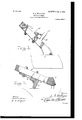
- Figure 1 is a side elevation of the present implement, showing it in its initial position in extracting a spike.
- Fig. 2 is a view similar to Fig. 1, showing a spike partly extracted.
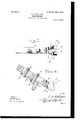
- Fig. 3 is a top plan view of the implement.
- Fig. 4 is a central longitudinal section of the implement.
- the present invention comprises a stock 5, which is enlarged laterally at one end to form a head 6, having a fiat forward face 7 which slants upwardly and rearwardly, and the head has a slight upward turn, as shown.
- a recess 8 is formed in the upper face of the head, and a slot 9 is formed in the forward face 7, longitudinally of the recess and communicating therewith, the slot opening through the upper and lower faces of the head.
- a second slot 10 is formed in the lower face of the head and extends longitudinally of the implement, this slot communicating with the slot 9 and with the recess 8 at its bottom, the recess extending laterally and rearwardly beyond the slot.
- a foot 13 is slidably mounted upon the under face of the slot adjacent to the head for movement longitudinally of the slot, and this foot includes an attachingplate 14, longitudinally slotted, asshown at 15, for the reception of attaching and clam ing bolts 16, which may be operated to ho d the foot against movement.
- the attachingplate carries a downwardly-extending proj ection 17 at its forward end, which is adapted for engagement with a rail, as will be presently described, or which may be rested upon a surface from which a spike is to be extracted to form a fulcrum.
- the extractor is disposed as shown in Fig. 1, the under face of the head being disposed against the web of a rail and the portions of the head at the sides of the slot 9 -being disposed at opposite sides of the head of a spike, the sharpened portions of a wall of a slot being engaged beneath the head of the spike.
- the implement is then operated to partially withdraw the spike, after which the implement is shifted to bring the head of the spike into the recess, with its stern extending downwardly through the slot 10, and the implement is then rocked backwardly over the rail, against the opposite side of which the projection of the foot has been engaged to extract the spike.
- the head includes cooperating inwardlydirected jaws, the mutually adjacent edges of which are tapered from their lower to their upper portions, as described, and which are adapted for engagement with the head of a spike.
- An implement of the class described comprising a stock having a head at one end, said head having an upwardly and rearwardly slanted forward face and having a recess opening through its upper face, said head also having communicating slots in its forward headed bolts carried by said stock and engag- I and lower faces communicating with the rein the slots formed in said rail-engaging foot.
Landscapes
- Engineering & Computer Science (AREA)
- Mechanical Engineering (AREA)
- Footwear And Its Accessory, Manufacturing Method And Apparatuses (AREA)
Description
No. 809,122. PATBNIBD JAN. 2, 1906.,
L. A. M 'GAM SPIKE ER.
APPLICATION FILED JUNI'. 16, 1905.
EEEEEEEEEEEEE 2.
UNITED STATES PATENT oFrioE.
'SPIKE-FULLER. f
Specification of Letters Patent.
Patented Jan. 2, 1906.
Application led June 16, 1905. Serial No. 265,626.
To LZ/ whom t may con/cern:
Beit known that I, LORENZO A. MILLIGAN, a citizen of the United States, residing at Barstow, in the county of San Bernardino, State of California, have invented certain new and useful Improvements in Spike-Fullers and I do hereby declare the following to be a full, clear, and exact description of the invention, such as will enable others skilled in the art to which it appertains to make and use the same.
This invention relates to spike-pullers, and has for its object to provide an implement of this nature with which railroad-spikes may be quickly and easily withdrawn from the ties and which will withdraw spikes without injuring them.
Another object is to provide an implement which will be adjustable to suit different conditions.
Other objects and advantages will be apparent from the following description, and it will be understood that changes in the specific construction shown and described may be made within the scope of the claim and that any suitable materials may be used without departing from the spirit of the invention.
4In the drawings forming a portion of this specification, and in which like numerals of reference indicate similar parts in the several views, Figure 1 is a side elevation of the present implement, showing it in its initial position in extracting a spike. Fig. 2 is a view similar to Fig. 1, showing a spike partly extracted. Fig. 3 is a top plan view of the implement. Fig. 4 is a central longitudinal section of the implement.
Referring now to the drawings, the present invention comprises a stock 5, which is enlarged laterally at one end to form a head 6, having a fiat forward face 7 which slants upwardly and rearwardly, and the head has a slight upward turn, as shown. A recess 8 is formed in the upper face of the head, and a slot 9 is formed in the forward face 7, longitudinally of the recess and communicating therewith, the slot opening through the upper and lower faces of the head. A second slot 10 is formed in the lower face of the head and extends longitudinally of the implement, this slot communicating with the slot 9 and with the recess 8 at its bottom, the recess extending laterally and rearwardly beyond the slot. At the sides of the slot 10 the material of the head is struck downwardly to form depending lips 11, and the walls of the slot 9 are tapered from their lower to their upper ends, the upper portions of these walls being sharpened, as shown at 12, for engagement beneath the head of the spike, as will be presently described. A foot 13 is slidably mounted upon the under face of the slot adjacent to the head for movement longitudinally of the slot, and this foot includes an attachingplate 14, longitudinally slotted, asshown at 15, for the reception of attaching and clam ing bolts 16, which may be operated to ho d the foot against movement. The attachingplate carries a downwardly-extending proj ection 17 at its forward end, which is adapted for engagement with a rail, as will be presently described, or which may be rested upon a surface from which a spike is to be extracted to form a fulcrum.
In use the extractor is disposed as shown in Fig. 1, the under face of the head being disposed against the web of a rail and the portions of the head at the sides of the slot 9 -being disposed at opposite sides of the head of a spike, the sharpened portions of a wall of a slot being engaged beneath the head of the spike. The implement is then operated to partially withdraw the spike, after which the implement is shifted to bring the head of the spike into the recess, with its stern extending downwardly through the slot 10, and the implement is then rocked backwardly over the rail, against the opposite side of which the projection of the foot has been engaged to extract the spike.
From the above description it will be seen that the head includes cooperating inwardlydirected jaws, the mutually adjacent edges of which are tapered from their lower to their upper portions, as described, and which are adapted for engagement with the head of a spike.
What is claimed is- An implement of the class described comprising a stock having a head at one end, said head having an upwardly and rearwardly slanted forward face and having a recess opening through its upper face, said head also having communicating slots in its forward headed bolts carried by said stock and engag- I and lower faces communicating with the rein the slots formed in said rail-engaging foot. ro
cess, the walls of the slotin the forward face beln testimony whereof I aniX my signature ing sharpened at their upper portions, dependin presence of two witnesses.
5 ing lips carried bythe head at the sides of the LORENZO A. MILLIGAN.
slot in its bottom, said lips lying in a plane Witnesses: slightly below the bottom of the said head, a GUY GooDlNG,
slotted rail-engaging foot on the stock, and D. C. HENDERSON.
Priority Applications (1)
| Application Number | Priority Date | Filing Date | Title |
|---|---|---|---|
| US26562605A US809122A (en) | 1905-06-16 | 1905-06-16 | Spike-puller. |
Applications Claiming Priority (1)
| Application Number | Priority Date | Filing Date | Title |
|---|---|---|---|
| US26562605A US809122A (en) | 1905-06-16 | 1905-06-16 | Spike-puller. |
Publications (1)
| Publication Number | Publication Date |
|---|---|
| US809122A true US809122A (en) | 1906-01-02 |
Family
ID=2877603
Family Applications (1)
| Application Number | Title | Priority Date | Filing Date |
|---|---|---|---|
| US26562605A Expired - Lifetime US809122A (en) | 1905-06-16 | 1905-06-16 | Spike-puller. |
Country Status (1)
| Country | Link |
|---|---|
| US (1) | US809122A (en) |
-
1905
- 1905-06-16 US US26562605A patent/US809122A/en not_active Expired - Lifetime
Similar Documents
| Publication | Publication Date | Title |
|---|---|---|
| US809122A (en) | Spike-puller. | |
| US1173882A (en) | Railroad-spike. | |
| US612407A (en) | Spike | |
| US505743A (en) | Alfred thomas abbott | |
| US1138456A (en) | Opener. | |
| US424081A (en) | Spike | |
| US328655A (en) | David cobbing and bussell j | |
| US1175824A (en) | Spike. | |
| US560497A (en) | Railroad-tie plate | |
| US519511A (en) | Thompson | |
| US154926A (en) | Improvement in nail-extractors | |
| US1010589A (en) | Railway-tie and fastener. | |
| US508877A (en) | James lorenzo gage | |
| US1152656A (en) | Railroad-spike. | |
| US1026020A (en) | Railway-tie and fastener. | |
| US991688A (en) | Railroad-spike. | |
| US303888A (en) | Spike-extractor | |
| US229776A (en) | Peeslt | |
| US567311A (en) | William r | |
| US433816A (en) | Railroad-spike | |
| US275256A (en) | Bar for aligning railway-rails | |
| US963330A (en) | Railroad-spike. | |
| US321298A (en) | Lewis howabd | |
| US597294A (en) | Device for drawing spikes | |
| US534558A (en) | Railroad-spike |