US8091136B2 - Packet transfer device, packet transfer method, and program - Google Patents
Packet transfer device, packet transfer method, and program Download PDFInfo
- Publication number
- US8091136B2 US8091136B2 US12/294,095 US29409507A US8091136B2 US 8091136 B2 US8091136 B2 US 8091136B2 US 29409507 A US29409507 A US 29409507A US 8091136 B2 US8091136 B2 US 8091136B2
- Authority
- US
- United States
- Prior art keywords
- packet
- harmful
- network interface
- search pattern
- removal apparatus
- Prior art date
- Legal status (The legal status is an assumption and is not a legal conclusion. Google has not performed a legal analysis and makes no representation as to the accuracy of the status listed.)
- Active, expires
Links
Images


Classifications
-
- H—ELECTRICITY
- H04—ELECTRIC COMMUNICATION TECHNIQUE
- H04L—TRANSMISSION OF DIGITAL INFORMATION, e.g. TELEGRAPHIC COMMUNICATION
- H04L63/00—Network architectures or network communication protocols for network security
- H04L63/02—Network architectures or network communication protocols for network security for separating internal from external traffic, e.g. firewalls
- H04L63/0227—Filtering policies
-
- H—ELECTRICITY
- H04—ELECTRIC COMMUNICATION TECHNIQUE
- H04L—TRANSMISSION OF DIGITAL INFORMATION, e.g. TELEGRAPHIC COMMUNICATION
- H04L45/00—Routing or path finding of packets in data switching networks
- H04L45/60—Router architectures
-
- H—ELECTRICITY
- H04—ELECTRIC COMMUNICATION TECHNIQUE
- H04L—TRANSMISSION OF DIGITAL INFORMATION, e.g. TELEGRAPHIC COMMUNICATION
- H04L63/00—Network architectures or network communication protocols for network security
- H04L63/14—Network architectures or network communication protocols for network security for detecting or protecting against malicious traffic
- H04L63/1441—Countermeasures against malicious traffic
-
- H—ELECTRICITY
- H04—ELECTRIC COMMUNICATION TECHNIQUE
- H04L—TRANSMISSION OF DIGITAL INFORMATION, e.g. TELEGRAPHIC COMMUNICATION
- H04L2101/00—Indexing scheme associated with group H04L61/00
- H04L2101/60—Types of network addresses
- H04L2101/618—Details of network addresses
- H04L2101/622—Layer-2 addresses, e.g. medium access control [MAC] addresses
-
- H—ELECTRICITY
- H04—ELECTRIC COMMUNICATION TECHNIQUE
- H04L—TRANSMISSION OF DIGITAL INFORMATION, e.g. TELEGRAPHIC COMMUNICATION
- H04L61/00—Network arrangements, protocols or services for addressing or naming
- H04L61/09—Mapping addresses
- H04L61/25—Mapping addresses of the same type
- H04L61/2596—Translation of addresses of the same type other than IP, e.g. translation from MAC to MAC addresses
Definitions
- the present invention relates to a packet transfer apparatus for transferring a packet received via a communication network to another apparatus.
- Obstruction accesses are increasing such as an attack in which a plurality of computers distributed in a network transmit packets to a specific server in unison so as to flood communication routes and stop the functions.
- a harmful packet removal apparatus includes a function for receiving a packet addressed to a specific server, determining whether the packet is a harmful packet for attacking, and transferring only a packet other than the harmful packet.
- harmful packets can be removed in the service provider side by providing the harmful packet removal apparatus in the service provider side.
- ISP Internet service provider
- the first method is a method for inserting the harmful packet removal apparatus into a connection line connecting to the customer as shown in FIG. 2 .
- this method it is necessary to introduce the harmful packet removal apparatus for each customer so that there is a problem in that the service becomes expensive.
- the second method is one as shown in FIG. 3 .
- the network of the service provider is configured by a plurality of routers, and the harmful packet removal apparatus is placed in an desired location in the network.
- routing information in the network of the service provider is rewritten for guiding a packet addressed to the customer network apparatus that is an attack target to the harmful packet removal apparatus. If a packet after passing the harmful packet removal apparatus is returned to the network as it is, the routers on the route transmit the packet back to the harmful packet removal apparatus so that the packet does not reach an intended destination.
- a tunnel is established from the harmful packet removal apparatus to a network of the customer so as to send packets from which harmful packets have been removed to the tunnel.
- the second method has a merit in that the harmful packet removal apparatus can be shared among a plurality of customers.
- the present invention is contrived in view of the above-mentioned points, and an object of the present invention is to provide a packet transfer technique that can transmit a packet matching a predetermined condition to a particular apparatus and can return a packet received from the particular apparatus to a network without changing routing information.
- a packet transfer apparatus for performing transfer of a packet that is received via a communication network, including:
- storage means configured to store at least a predetermined search pattern and an address identifying a predetermined apparatus
- determination means configured to determine whether predetermined data in a packet received from a network interface matches the search pattern
- output interface determination means configured to determine a network interface for outputting the packet using the determination result by the determination means
- address replacement means configured to replace an address identifying a destination apparatus of the packet with an address identifying the predetermined apparatus when outputting the packet from a network interface connected to the predetermined apparatus;
- packet sending means configured to send the packet to the network interface determined by the output interface determination means.
- the output interface determination means may be configured to determine the network interface for outputting the packet based on the determination result by the determination means and the network interface from which the packet is received.
- the output interface determination means may be configured to determine to output the packet from a network interface connected to the predetermined apparatus.
- the packet transfer apparatus may output the packet from a network interface corresponding to a destination described in the packet without performing determination by the determination means.
- the output interface determination means may determine to output the packet from a predetermined network interface as corresponding to the network interface from which the packet is received.
- an Ethernet address of the apparatus may be used.
- the present invention may be also configured as a packet transfer method corresponding to the operation of the packet transfer apparatus, and a non-transitory computer readable storage medium that stores a program causing a computer and the like to execute processes of the packet transfer apparatus.
- a packet transfer technique that can transmit a packet matching a predetermined condition to a particular apparatus and can return a packet received from the particular apparatus to a network without changing routing information can be provided.
- FIG. 1 is a diagram for explaining a service using a harmful packet removal apparatus
- FIG. 2 is a diagram for explaining a first method using the harmful packet removal apparatus in a conventional technology
- FIG. 3 is a diagram for explaining a second method using the harmful packet removal apparatus in a conventional technology
- FIG. 4 is a diagram for explaining an outline of the first embodiment of the present invention.
- FIG. 5 is a connection configuration of a packet transfer apparatus
- FIG. 6 is a detailed functional block diagram of the packet transfer apparatus
- FIG. 7 is a diagram for explaining basic operations of the packet transfer apparatus in the first embodiment
- FIG. 8 is a diagram for explaining a service handled in an applied operation of the packet transfer apparatus in the first embodiment
- FIG. 9 is a diagram for explaining the applied operation of the packet transfer apparatus in the first embodiment.
- FIG. 10 is a diagram for explaining the applied operation of the packet transfer apparatus in the first embodiment
- FIG. 11 is a diagram showing a configuration when two harmful packet removal apparatuses are connected to the packet transfer apparatus
- FIG. 12 is a detailed functional block diagram of the packet transfer apparatus in the second embodiment.
- FIG. 13 is a diagram for explaining basic operations of the packet transfer apparatus in the second embodiment
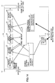
- FIG. 14 is a diagram showing a configuration of the packet transfer apparatus when a plurality of harmful packet removal apparatuses are connected to the packet transfer apparatus in the second embodiment.
- FIG. 4 shows a use example of a packet transfer apparatus 10 in the present embodiment.
- the packet transfer apparatus 10 of the present embodiment is inserted into a location where a packet that goes toward an attack target passes.
- a harmful packet removal apparatus 30 is connected to the packet transfer apparatus 10 of the present embodiment.
- the packet transfer apparatus 10 includes functions for selecting only a packet going toward the attack target from among packets that pass through the packet transfer apparatus 10 to send the selected packet to the harmful packet removal apparatus 30 , and returning a packet that has passed through the harmful packet removal apparatus 30 (that has been determined to be harmless) to a traffic going toward the attack target.
- the above-mentioned functions are realized without changing routing information and also without using a tunnel.
- the network of the service provider is configured by connecting routers in a multistage manner, and the packet transfer apparatus 10 is inserted before a router that accommodates the customer. But, the packet transfer apparatus 10 need not necessarily be connected to the customer accommodating router directly.
- FIG. 5 shows a connection configuration of the packet transfer apparatus 10 .
- the customer accommodating router or a router in a side closer to the customer accommodating router in relation to an inserting point of the packet transfer apparatus 10 is called a downstream router, and a router in a side transmitting, toward the downstream router, packets addressed to the customer is called an upstream router.
- the packet transfer apparatus 10 of the present embodiment is provided with at least three network interfaces ( 0 - 2 ).
- the interface 0 is connected to the upstream router 40
- the interface 1 is connected to the downstream router 50
- the interface 2 is connected to the harmful packet removal apparatus 30 .
- the packet transfer apparatus 10 includes a function for performing pattern matching for an arbitrary length at an arbitrary position in a received packet, a function for determining an output interface based on an input interface that receives the packet and a result of the pattern matching, and a replacement function for replacing an Ethernet address in a header of the packet with an Ethernet address of a sending destination of the packet for obtaining conformity with a conventional network apparatus such as a switch and a router and the like.
- a conventional network apparatus such as a switch and a router and the like.
- the Ethernet is a standard used for exchanging packets between IP network apparatuses such as routers, and the packet includes in its inside Ethernet addresses of a destination and a source.
- the destination/source Ethernet addresses are different from a destination IP address in an IP packet in the packet.
- destination address when “destination address” is simply described, it indicates a destination IP address.
- FIG. 6 shows a detailed functional block diagram of the packet transfer apparatus 10 .
- the packet transfer apparatus 10 includes interfaces ( 11 ), a packet reception unit 12 , a pattern matching execution unit 13 , an output interface determination unit 14 , an Ethernet address replacement unit 15 , a packet sending unit 16 , a pattern setting unit 17 , and a packet buffer 18 .
- the packet transfer apparatus 10 includes a storage apparatus such as a memory, and the storage apparatus stores a search pattern table 19 , an Ethernet address table 20 and the like.
- the packet transfer apparatus 10 includes an interface 21 for inputting setting information.
- the interfaces 11 are function units for connecting to an external apparatus. For the sake of convenience, although the interfaces 11 are located in the left end and the right end in FIG. 6 , they are physically implemented at a same location as a pair for input and output.
- the packet reception unit 12 includes a function for receiving a packet via the interface 11 , and recording the packet body and an input interface used for reception into the packet buffer 18 .
- the pattern setting unit 17 includes a function for setting a list of search patterns and corresponding pairs of input and output interfaces, and a table of Ethernet addresses of apparatuses connected to each interface.
- the search pattern table 19 records information indicating that, when a packet having a destination IP address of 192.168.24.3 is input from the input interface 0 , the packet is output to the output interface 2 , and the like.
- the Ethernet address table 20 records information indicating that an Ethernet address of an apparatus connected to the interface 0 is 0:ab:00:11:11:11, and the like.
- the pattern matching execution unit 13 includes a function for using the search pattern stored by the pattern setting unit 17 to check whether a received packet matches the search pattern, and recording the pattern number if they match.
- the output interface determination unit 14 includes a function for using the check result by the pattern matching execution unit 12 and the input interface used for reception to determine an output interface from the pair of input and output interfaces corresponding to the search pattern in the search pattern table.
- the Ethernet address replacement unit 15 replaces a destination Ethernet address part of the packet with an Ethernet address of the apparatus. That is, if the output interface determination unit 14 determines to send a packet to a destination different from the original destination, there is a case in which some connecting apparatuses do not receive the packet since the destination Ethernet address of the packet does not agree with that of the connection apparatus itself. Thus, the destination Ethernet address of the packet is replaced with the Ethernet address of the apparatus connected to the output interface.
- the packet sending unit 16 includes a function for sending a packet to an output interface determined by the output interface determination unit 14 .
- the packet transfer apparatus 10 shown in FIG. 6 can be implemented by hardware.
- the packet transfer apparatus 10 can be also realized by installing a program for executing processes of each functional unit into a computer having network interfaces.
- the program can be stored in a recording medium such as a memory and a CD-ROM and the like and can be installed into the computer from the recording medium.
- the computer is an apparatus that includes a CPU and a memory and can execute a program, and a router is included in the computer, for example.
- a service manager uses the interface 21 for inputting settings so as to input a search pattern for a packet that should be sent to the harmful packet removal apparatus 30 and a pair of input and output interfaces to be used when the packet matches the search pattern.
- an IP address of a server of an attack target is set to be the search pattern, and pairs of the input and output interfaces are set to be (upstream router, harmful packet removal apparatus), (downstream router, upstream router) and (harmful packet removal apparatus, downstream router). That is, when pattern matching between a destination IP address part of a received packet and a search pattern is performed and when they match, the packet received from the upstream router 40 is sent to the harmful packet removal apparatus 30 , the packet received from the downstream router 50 is sent to the upstream router 40 , and the packet received from the harmful packet removal apparatus 30 is sent to the downstream router 50 .
- the search pattern is not limited to an IP address. For example, any one or a set of more than one of an IP address, a port number and a TCP flag may be used as the search pattern.
- the pattern setting unit 17 receives the information, and stores it as a search pattern to be referred to by the pattern matching execution unit 13 .
- a plurality of sets of search patterns and pairs of input and output can be written. Accordingly, a plurality of attack targets can be handled simultaneously.
- pairs of default input and output interfaces are set as (upstream router, downstream router), (downstream router, upstream router) and (harmful packet removal apparatus, upstream router).
- Ethernet addresses of the upstream router, the downstream router and the harmful packet removal apparatus are input to the Ethernet address table.
- the packet reception unit 12 receives the packet from an input interface connected to the upstream router 40 , and stores the packet with input interface information in the packet buffer 18 .
- the pattern matching execution unit 13 checks whether the packet matches the search pattern, and records the result (does not match in this case).
- the output interface determination unit 14 determines an output interface from the pattern matching result and the input interface information. In this case, since the packet does not match the search pattern, the output interface determination unit 14 determines to output the packet to the downstream router 50 according to a pair (upstream router, downstream router) of the default input and output interfaces.
- the Ethernet address replacement unit 15 replaces a destination Ethernet address in the packet according to an output interface. But, in this case, the upstream router 40 sends the packet to the downstream router 50 , and since it is the same as the output destination of the packet transfer apparatus 10 , the packet does not change. Then, the packet sending unit 16 sends the packet to the output interface to which the downstream router 50 is connected.
- the packet reception unit 12 receives a packet from a network interface connected to the upstream router 40 , and stores the packet into the packet buffer 18 with input interface information. Then, the pattern matching execution unit 13 checks whether the packet matches the search pattern and records the result (matches in this case).
- the output interface determination unit 14 determines an output interface from the pattern matching result and the input interface information. In this case, since the packet matches the search pattern, the output interface determination unit 14 determines to output the packet to the harmful packet removal apparatus 30 . Then, the Ethernet address replacement unit 15 replaces the destination Ethernet address in the packet according to the output interface. In this case, the destination Ethernet address is rewritten with the Ethernet address of the harmful packet removal apparatus 30 . The packet sending unit 16 sends the packet to the output interface connected to the harmful packet removal apparatus 30 .
- the harmful packet removal apparatus 30 receives a packet that matches the search pattern, and sends out only harmless packets in received packets, there is no case in which a packet received from the harmful packet removal apparatus 30 does not match the search pattern in ordinary cases. But, for covering every case, this case is described.
- the packet reception unit 12 receives a packet from an input interface, and stores the packet into the packet buffer 18 with input interface information.
- the pattern matching execution unit 13 checks whether the packet matches the search pattern and records the result (does not match in this case).
- the output interface determination unit 14 determines an output interface from the pattern matching result and the input interface information. In this case, the packet does not match the search pattern and is received from the harmful packet removal apparatus 30 , the output interface determination unit 14 determines to output the packet to the upstream router 40 .
- the Ethernet address replacement unit 15 replaces the destination Ethernet address in the packet with the Ethernet address of the upstream router 40 according to the output interface, and the packet sending unit 16 sends the packet to the output interface connected to the upstream router 40 .
- This packet corresponds to a packet that has been certified not to be an attack packet among packets sent to the harmful packet removal apparatus 30 in (operation 2). That is, there is a case in which content of the packet is the same as the packet handled in (operation 2).
- the packet reception unit 12 receives a packet from an input interface, and stores the packet into the packet buffer 18 with input interface information.
- the pattern matching execution unit 13 checks whether the packet matches the search pattern and records the result (matches in this case).
- the output interface determination unit 14 determines an output interface from the pattern matching result and the input interface information.
- the packet matches the search pattern, and is received from the harmful packet removal apparatus 30 , the output interface determination unit 14 determines to output the packet to the downstream router 50 .
- the Ethernet address replacement unit 15 replaces the destination Ethernet address in the packet according to the output interface.
- the destination Ethernet address is replaced with the Ethernet address of the downstream router 50 .
- the packet sending unit 16 sends the packet to the output interface.
- the packet reception unit 12 receives a packet from an input interface, and stores the packet into the packet buffer 18 with input interface information.
- the pattern matching execution unit 13 checks whether the packet matches the search pattern and records the result (does not match in this case).
- the output interface determination unit 14 determines an output interface from the pattern matching result and the input interface information. In this case, since the packet does not match the search pattern, the output interface determination unit 14 determines to output the packet to the upstream router 40 .
- the Ethernet address replacement unit 15 replaces the Ethernet address in the packet according to the output interface. But, in this case, since the downstream router 50 sends the packet to the upstream router 40 , the packet does not change. Then, the packet sending unit 30 sends the packet to an output interface connected to the upstream router 40 .
- downstream router 50 Since the downstream router 50 knows that there is the attack target under the downstream router 50 , this operation does not occur in ordinary cases. But, for covering every case, this case is described.
- the packet reception unit 12 receives a packet from an input interface, and stores the packet into the packet buffer 18 with input interface information.
- the pattern matching execution unit 13 checks whether the packet matches the search pattern and records the result (matches in this case). Then, the output interface determination unit 14 determines an output interface from the pattern matching result and the input interface information. In this case, although the packet matches the search pattern, since the packet is received from the downstream router 50 , the output interface determination unit 14 determines to output the packet to the upstream router 40 .
- the Ethernet address replacement unit 15 replaces the destination Ethernet address in the packet according to the output interface. In this case, the address is replaced with the Ethernet address of the upstream router 40 .
- the packet sending unit 16 sends the packet to the output interface.
- harmful packet removal apparatuses 30 there is one that performs operation as a relay apparatus of a service in addition to the operation as a simple filter as described in the above-mentioned examples.
- the harmful packet removal apparatus 30 that performs such operation as a relay apparatus is used for addressing an attack in which a client sends a connection request to a server, but the client does not perform processes after that so as to consume resources of the server in a client and server model such as http protocol.
- the packet transfer apparatus 10 of the present embodiment can also properly address the harmful packet removal apparatus 30 performing such operation.
- an attack target that the harmful packet removal apparatus 30 will protect is referred to as “server”
- a source of a packet that tries to access the sever is referred to as “client”
- a service relay function in the harmful packet removal apparatus 30 is referred to as a relay apparatus 35 .
- a connection request is sent from the client to the server (step 1 )
- a connection permission is sent from the server to the client (step 2 ).
- a data request is sent from the client to the server (step 3 ), and data transmission is performed from the server to the client (step 4 ).
- a search pattern is added to the packet transfer apparatus 10 .
- a search condition of a packet is made such that a destination IP address of the packet is required to be an IP address (to be referred to as an address of the relay apparatus hereinafter) used for the relay apparatus 35 set in the harmful packet removal apparatus 30 , and pairs of input and output interfaces used when the search condition is satisfied are set to be (upstream router, downstream router), (downstream router, harmful packet removal apparatus) and (harmful packet removal apparatus, upstream router), so that a search pattern is added.
- a parenthesized number indicates a packet, and it corresponds to a number added at the end of “packet” in the following descriptions.
- connection request packet ( 1 ) sent from the client to the server is described.
- This packet ( 1 ) is received by the packet transfer apparatus 10 from the upstream router 40 . Since this packet ( 1 ) corresponds to the case of the operation 2 in the basic operations, this packet ( 1 ) is sent to the harmful packet removal apparatus 30 .
- the relay apparatus 35 in the harmful packet removal apparatus 30 returns (on behalf of the server) a response packet ( 2 ) to the client.
- the source of the packet is the server and the destination is the client. Since the packet ( 2 ) corresponds to the case of operation 3 in the basic operations, the packet ( 2 ) is sent to the upstream router 40 and reaches the client.
- This packet ( 3 ) is received by the packet transfer apparatus 10 from the upstream router 40 .
- this packet ( 3 ) is sent to the harmful packet removal apparatus 30 .
- the relay apparatus 35 sends a connection request packet ( 4 ) to the server.
- This packet ( 4 ) has an address, as a source, for relay function used in adding of the search pattern, and has an address of the server as a destination.
- the packet transfer apparatus 10 Since this packet ( 4 ) corresponds to the operation 4 of the basic operations, the packet transfer apparatus 10 outputs the packet ( 4 ) to the downstream router 50 , so that the packet ( 4 ) reaches the server. Next, the server outputs a connection permission packet ( 5 ) in response to the connection request ( 4 ).
- the destination of the connection permission packet ( 5 ) is the address of the relay apparatus, and the packet ( 5 ) enters the packet transfer apparatus 10 from the downstream router 50 .
- the packet ( 5 ) corresponds to the added search pattern, the packet ( 5 ) is output to the harmful packet removal apparatus 30 . Since the relay apparatus 35 receives the connection permission ( 5 ), the relay apparatus 35 sends a data request packet ( 6 ) to the server. Since the data request packet ( 6 ) corresponds to the operation 4 of the basic operations, the packet ( 6 ) is output to the downstream router 50 and reaches the server.
- the server outputs a data packet ( 7 ) in response to the data request ( 6 ).
- the destination of the data packet ( 7 ) is an address of the relay apparatus 35 that is a source of the data request.
- This packet ( 7 ) enters the packet transfer apparatus 10 from the downstream router. Since this packet ( 7 ) corresponds to the added search pattern, the packet ( 7 ) is output to the harmful packet removal apparatus 30 .
- the relay apparatus 35 receives the data ( 7 ) and transfers the data to the client.
- the source is the address of the server and the destination is the address of the client. Since this packet ( 8 ) corresponds to the operation 3 of the basic operations, the packet ( 8 ) is output to the upstream router 40 and reaches the client.
- FIG. 11 shows a configuration when two harmful packet removal apparatuses are connected.
- the packet transfer apparatus 10 of the present embodiment for connecting a plurality of harmful packet removal apparatuses, there is no need to specially change the apparatus except that pairs of input and output interfaces are added.
- the size of the Ethernet address is six bytes, and when memory read and write is performed in units of eight bytes in hardware that configures the packet transfer apparatus 10 of the present embodiment, rewriting of the destination Ethernet address of a packet on the packet buffer 18 configured by the memory can be performed according to the following procedure.
- eight bytes (head two bytes are the last two bytes of a source Ethernet address) including the destination Ethernet address of the packet recorded in the packet buffer 18 is read from the packet buffer 18 . Then, the part of the two bytes other than the destination Ethernet address is obtained from the read data, and eight bytes that should be written are loaded on a register, and the data on the register is written into the packet buffer 18 .
- Ethernet addresses of connected apparatuses are known and a source Ethernet address of a packet received from an interface is also recorded.
- speed-up for rewriting the destination Ethernet address can be realized as follows.
- the packet transfer apparatus 10 determines an output interface from a search pattern of the packet and an input interface.
- the output interface is determined only from the search pattern.
- a basic connection form of the packet transfer apparatus 10 in the second embodiment is shows as FIG. 4 similarly to the first embodiment.
- FIG. 12 shows a detailed configuration of the packet transfer apparatus 10 in the second embodiment.
- the basic configuration is similar to the configuration of the packet transfer apparatus of the first embodiment. But, since the output interface is determined only from the search pattern when the packet matches the search pattern in the second embodiment, information recorded in the search pattern table 19 and the Ethernet address table 20 and the like is different. In the following, the configuration of the packet transfer apparatus 10 of the second embodiment is described mainly for points different from the first embodiment.
- the packet reception unit 12 includes a function for receiving a packet via the interface, and storing the packet body and an input interface used for the reception into the packet buffer 18 .
- the pattern setting unit 17 records only search patterns as the search pattern table 19 .
- the Ethernet address table 20 the Ethernet address of the harmful packet removal apparatus 30 is recorded.
- the pattern matching execution unit 13 includes a function for using the search pattern stored by the pattern setting unit 17 to check whether a received packet matches the search pattern, and recording a result whether they match.
- the output interface determination unit 14 includes a function for determining an output interface based on the check result by the pattern matching execution unit 13 .
- the Ethernet address replacement unit 15 includes a function for replacing a destination Ethernet address part of the packet with an Ethernet address of the harmful packet removal apparatus 30 recorded in the Ethernet address table 20 when outputting a packet to the harmful packet removal apparatus 30 .
- a search pattern of a packet is made such that an IP address of a server of an attack target is required to exist in the part of the destination address, and the pattern is stores.
- a packet that matches the search pattern is sent to the harmful packet removal apparatus 30 .
- a plurality of search patterns can be recorded, so that it becomes possible to handle a plurality of attack targets at the same time.
- the Ethernet address of the harmful packet removal apparatus 30 is input into the Ethernet address table 20 .
- comparison of the search pattern is performed for only a packet input from the upstream router 40 or the downstream router 50 , and comparison of the search pattern for a packet from the harmful packet removal apparatus 30 is not performed.
- output interfaces are predetermined to be upstream router ⁇ downstream router, downstream router ⁇ upstream router, harmful packet removal apparatus ⁇ upstream router or downstream router (according to a sending destination specified by the harmful packet removal apparatus). That is, when a packet does not match any search pattern, the packet received from the upstream router 40 is sent to the downstream router 50 , the packet received from the downstream router 50 is sent to the upstream router 40 .
- a packet received from the harmful packet removal apparatus 30 is sent to the upstream router 40 or the downstream router 50 according to a sending destination (destination Ethernet address) specified by the harmful packet removal apparatus. That is, the packet transfer apparatus has information of destination Ethernet addresses of the upstream router 40 and the downstream router 50 , and network interfaces corresponding to them, so that the packet transfer apparatus sends the packet to a sending destination specified by the harmful packet removal apparatus based on the information.
- the packet reception unit 12 receives the packet from an input interface, and stores the packet with input interface information in the packet buffer 18 .
- the pattern matching execution unit 13 performs pattern matching to record a result that the packet does not match any search pattern. Since the packet does not match any search pattern, the output interface determination unit 14 determines to output the packet to the downstream router 50 , and the packet sending unit 16 sends the packet to the output interface to which the downstream router 50 is connected.
- the packet reception unit 12 receives a packet from an input interface, and stores the packet into the packet buffer 18 with input interface information.
- the pattern matching execution unit 13 records a result that the packet match a search pattern. Since the packet match the search pattern, the output interface determination unit 14 determines to output the packet to the harmful packet removal apparatus 30 . Then, the Ethernet address replacement unit 15 replaces the destination Ethernet address of the packet with the Ethernet address of the harmful packet removal apparatus 30 , and the packet sending unit 16 sends the packet to the output interface connected to the harmful packet removal apparatus 30 .
- the packet reception unit 12 receives a packet from an input interface, and stores the packet into the packet buffer 18 with input interface information.
- the pattern matching execution unit 13 checks whether the packet match a search pattern, and records a result that the packet does not match any search pattern. Since the packet does not match any search pattern, the output interface determination unit 14 determines to output the packet to the upstream router 40 , and the packet sending unit 16 sends the packet to the output interface connected to the upstream router 40 .
- the packet reception unit 12 receives a packet from an input interface, and stores the packet into the packet buffer 18 with input interface information.
- the pattern matching execution unit 13 performs pattern matching to record a result that the packet matches a search pattern. Since the packet matches the search pattern, the output interface determination unit 14 determines to output the packet to the harmful packet removal apparatus 30 . Then, the Ethernet address replacement unit 15 replaces the destination Ethernet address of the packet with the Ethernet address of the harmful packet removal apparatus 30 , and the packet sending unit 16 sends the packet to the output interface connected to the harmful packet removal apparatus 30 .
- This packet corresponds to a packet that has been certified not to be an attack packet among packets sent to the harmful packet removal apparatus in operation 2. That is, there is a case in which content of the packet is the same as the packet handled in operation 2.
- the packet reception unit 12 receives a packet from an input interface, and stores the packet into the packet buffer 18 with input interface information.
- the output interface determination unit 14 follows an output destination designation (designated as a destination Ethernet address of the packet) by the harmful packet removal apparatus 30 . Since the downstream router 50 is designated in ordinary cases, it is assumed that the downstream router 50 is designated also in this embodiment.
- the packet sending unit 16 sends the packet to the output interface connected to the downstream router 50 .
- the packet transfer apparatus 10 can be applied to a harmful packet removal apparatus 30 that operates as a relay apparatus 35 .
- an applied service is one shown in FIG. 8 .
- the relay apparatus 35 is provided with a specific routing information table, and is provided with a function for outputting a packet by adding a destination Ethernet address of the downstream router 50 when the packet is for the server, and by adding a destination Ethernet address of the upstream router 50 for other packets.
- a search pattern is added in which a search condition is set such that an IP address (to be referred to as an address of the relay apparatus hereinafter) used for the relay apparatus 35 set in the harmful packet removal apparatus 30 is required to exist in the destination address. That is, in addition to the case described in the basic operations, the packet transfer apparatus 10 sends the packet to the harmful packet removal apparatus 30 also when the packet matches the address of the relay apparatus.
- a parenthesized number indicates a packet, and corresponds to a number added at the end of “packet” in the following descriptions.
- connection request packet ( 1 ) sent from the client to the server is described.
- This packet ( 1 ) is received by the packet transfer apparatus 10 from the upstream router 40 . Since this packet ( 1 ) corresponds to the case of the operation 2 in the basic operations, this packet ( 1 ) is sent to the harmful packet removal apparatus 30 .
- the relay apparatus 35 in the harmful packet removal apparatus 30 returns (on behalf of the server) a response packet ( 2 ) to the client.
- the source of the packet is the server and the destination is the client.
- this packet ( 2 ) corresponds to the case of operation 5 of the basic operations, since the destination Ethernet address of the packet sent from the harmful packet removal apparatus 30 is the Ethernet apparatus of the upstream router 40 , the packet transfer apparatus 10 sends the packet ( 2 ) to the upstream router 40 , so that the packet ( 2 ) reaches the client.
- This packet ( 3 ) is received by the packet transfer apparatus 10 from the upstream router 40 .
- this packet ( 3 ) is sent to the harmful packet removal apparatus 30 .
- the relay apparatus 35 sends a connection request packet ( 4 ) to the server.
- This packet ( 4 ) has an address, as a source, for relay function used in adding of the search pattern, and has an address of the server as a destination.
- This packet ( 4 ) is output to the downstream router 50 according to the operation 5 of the basic operations, and reaches the server.
- the server outputs a connection permission packet ( 5 ) for the connection request ( 4 ).
- the destination of the connection permission packet ( 5 ) is the address of the relay apparatus, and the packet ( 5 ) enters the packet transfer apparatus 10 from the downstream router 50 .
- the packet ( 5 ) corresponds to the added search pattern, the packet ( 5 ) is output to the harmful packet removal apparatus 30 . Since the relay apparatus 35 receives the connection permission ( 5 ), the relay apparatus 35 sends a data request packet ( 6 ) to the server.
- the packet ( 6 ) is output to the downstream router 50 according to the operation 5 of the basic operations and reaches the server. Then, the server outputs a data packet ( 7 ) in response to the data request ( 6 ).
- the destination of the data packet ( 7 ) is an address of the relay apparatus 35 that is a source of the data request. This packet ( 7 ) enters the packet transfer apparatus 10 from the downstream router 50 .
- this packet ( 7 ) corresponds to the added search pattern, the packet ( 7 ) is output to the harmful packet removal apparatus 30 .
- the relay apparatus 35 receives the data ( 7 ) and transfers the data to the client.
- the source is the address of the server and the destination is the address of the client.
- the packet transfer apparatus that received the packet from the harmful packet removal apparatus 30 outputs the packet ( 8 ) to the upstream router 40 according to the operation 5 of the basic operations. Then, the packet ( 8 ) reaches the client.
- FIG. 14 the inside of the packet transfer apparatus 10 is configured as shown in FIG. 14 .
- the configuration shown in FIG. 14 is different from the case in which one harmful packet removal apparatus 30 is connected in the following points.
- an interface to which a packet is output when matching is specified for each search pattern.
- an Ethernet address of the harmful packet removal apparatus is recorded for each harmful packet removal apparatus.
- the output interface determination unit 14 outputs the packet to an output interface specified by the matched search pattern.
- the Ethernet address replacement unit 15 replaces the destination Ethernet address of the packet with an Ethernet address corresponding to a harmful packet removal apparatus connected to an interface specified as the output interface.
- Ethernet address replacement unit 15 It is also possible to perform speed-up of the Ethernet address replacement unit 15 in the same way as the first embodiment. However, it is necessary to set Ethernet addresses of the upstream and downstream routers beforehand.
- the packet transfer apparatus of the embodiments of the present invention is different from routers configuring a conventional network in the following points.
- the packet transfer apparatus determines an output interface without using routing information, but using a specific pattern in the packet.
- the packet transfer apparatus of the first embodiment especially uses input interface information for determining an output interface, it is possible to specify different output interfaces when packets having a same destination address enter from different interfaces. But, the router outputs a packet having a same destination address to a same output interface irrespective of the interface from which the packet is input.
- the packet transfer apparatus can use any information other than the destination address in the packet for determining an output interface.
- the packet transfer apparatus since it is not necessary to change routing information of routes and it is not necessary to introduce the tunnel, it becomes unnecessary to add a tunnel termination apparatus in the customer network side, and a service can be realized without increasing new settings and load in the routers.
- packets to be sent to the harmful packet removal apparatus can be limited when these pieces of information of an attack that is desired to be removed are known. This has an effect to decrease load of the harmful packet removal apparatus.
- the harmful packet removal apparatus is connected to the packet transfer apparatus in the present embodiments, it is not limited to the harmful packet removal apparatus, and any apparatus can be connected to the packet transfer apparatus.
Landscapes
- Engineering & Computer Science (AREA)
- Computer Security & Cryptography (AREA)
- Computer Networks & Wireless Communication (AREA)
- Signal Processing (AREA)
- Computer Hardware Design (AREA)
- Computing Systems (AREA)
- General Engineering & Computer Science (AREA)
- Data Exchanges In Wide-Area Networks (AREA)
Applications Claiming Priority (3)
| Application Number | Priority Date | Filing Date | Title |
|---|---|---|---|
| JP2006081588A JP4776412B2 (ja) | 2006-03-23 | 2006-03-23 | パケット転送装置、パケット転送方法、及びプログラム |
| JP2006-081588 | 2006-03-23 | ||
| PCT/JP2007/055893 WO2007119491A1 (ja) | 2006-03-23 | 2007-03-22 | パケット転送装置、パケット転送方法、及びプログラム |
Publications (2)
| Publication Number | Publication Date |
|---|---|
| US20090126004A1 US20090126004A1 (en) | 2009-05-14 |
| US8091136B2 true US8091136B2 (en) | 2012-01-03 |
Family
ID=38609276
Family Applications (1)
| Application Number | Title | Priority Date | Filing Date |
|---|---|---|---|
| US12/294,095 Active 2028-10-28 US8091136B2 (en) | 2006-03-23 | 2007-03-22 | Packet transfer device, packet transfer method, and program |
Country Status (5)
| Country | Link |
|---|---|
| US (1) | US8091136B2 (de) |
| EP (1) | EP1998520B1 (de) |
| JP (1) | JP4776412B2 (de) |
| CN (1) | CN101406011A (de) |
| WO (1) | WO2007119491A1 (de) |
Families Citing this family (2)
| Publication number | Priority date | Publication date | Assignee | Title |
|---|---|---|---|---|
| RU2558624C2 (ru) * | 2010-09-22 | 2015-08-10 | Нек Корпорейшн | Устройство управления, система связи, способ связи и носитель записи, содержащий записанную на нем программу для связи |
| US10757105B2 (en) | 2017-06-12 | 2020-08-25 | At&T Intellectual Property I, L.P. | On-demand network security system |
Citations (20)
| Publication number | Priority date | Publication date | Assignee | Title |
|---|---|---|---|---|
| US20030202510A1 (en) * | 2002-04-26 | 2003-10-30 | Maxxan Systems, Inc. | System and method for scalable switch fabric for computer network |
| US20030202520A1 (en) * | 2002-04-26 | 2003-10-30 | Maxxan Systems, Inc. | Scalable switch fabric system and apparatus for computer networks |
| US20040030766A1 (en) * | 2002-08-12 | 2004-02-12 | Michael Witkowski | Method and apparatus for switch fabric configuration |
| JP2004320453A (ja) | 2003-04-16 | 2004-11-11 | Nippon Telegr & Teleph Corp <Ntt> | 不正アクセス警告装置とそのプログラム |
| US20050152354A1 (en) * | 2002-03-05 | 2005-07-14 | Francois Abel | Method and systems for ordered dynamic distribution of packet flows over network processing means |
| US20060002386A1 (en) | 2004-06-30 | 2006-01-05 | Zarlink Semiconductor Inc. | Combined pipelined classification and address search method and apparatus for switching environments |
| US20060002292A1 (en) | 2004-06-30 | 2006-01-05 | Zarlink Semiconductor Inc. | Method and apparatus providing rapid end-to-end failover in a packet switched communications network |
| JP2006067078A (ja) | 2004-08-25 | 2006-03-09 | Nippon Telegr & Teleph Corp <Ntt> | ネットワークシステムおよび攻撃防御方法 |
| US7079537B1 (en) * | 2000-04-25 | 2006-07-18 | Advanced Micro Devices, Inc. | Layer 3 switching logic architecture in an integrated network switch |
| US20060159088A1 (en) * | 2005-01-14 | 2006-07-20 | Aghvami Abdol H | Network mobility |
| WO2006117013A1 (en) * | 2005-05-04 | 2006-11-09 | Telecom Italia S.P.A. | Method and system for processing packet flows, and computer program product therefor |
| US20070047583A1 (en) * | 2005-08-29 | 2007-03-01 | Siemens Aktiengesellschaft | Method for using a short address in a packet header |
| US7254639B1 (en) * | 2002-05-20 | 2007-08-07 | Cisco Technology, Inc. | Methods and apparatus for directing packets among a group of processors |
| US20070195777A1 (en) * | 2006-02-21 | 2007-08-23 | Tatar Mohammed I | Pipelined packet switching and queuing architecture |
| US7424744B1 (en) * | 2002-03-05 | 2008-09-09 | Mcafee, Inc. | Signature based network intrusion detection system and method |
| US7493659B1 (en) * | 2002-03-05 | 2009-02-17 | Mcafee, Inc. | Network intrusion detection and analysis system and method |
| US7529242B1 (en) * | 2002-02-15 | 2009-05-05 | Symantec Corporation | Routing network packets for multi-processor network flow analysis |
| US7609629B2 (en) * | 2005-04-06 | 2009-10-27 | Alaxala Networks Corporation | Network controller and control method with flow analysis and control function |
| US7620046B2 (en) * | 2004-09-30 | 2009-11-17 | Intel Corporation | Dynamically assigning packet flows |
| US7808897B1 (en) * | 2005-03-01 | 2010-10-05 | International Business Machines Corporation | Fast network security utilizing intrusion prevention systems |
Family Cites Families (7)
| Publication number | Priority date | Publication date | Assignee | Title |
|---|---|---|---|---|
| US5790554A (en) | 1995-10-04 | 1998-08-04 | Bay Networks, Inc. | Method and apparatus for processing data packets in a network |
| US6570875B1 (en) * | 1998-10-13 | 2003-05-27 | Intel Corporation | Automatic filtering and creation of virtual LANs among a plurality of switch ports |
| US6990101B1 (en) * | 2001-03-23 | 2006-01-24 | Advanced Micro Devices, Inc. | System and method for performing layer 3 switching in a network device |
| US7536715B2 (en) | 2001-05-25 | 2009-05-19 | Secure Computing Corporation | Distributed firewall system and method |
| JP3794491B2 (ja) | 2002-08-20 | 2006-07-05 | 日本電気株式会社 | 攻撃防御システムおよび攻撃防御方法 |
| JP3784799B2 (ja) * | 2003-11-13 | 2006-06-14 | 日本電信電話株式会社 | 攻撃パケット防御システム |
| US7107143B2 (en) * | 2004-07-21 | 2006-09-12 | General Motors Corporation | Estimation of oxygen concentration in the intake manifold of an unthrottled lean burn engine |
-
2006
- 2006-03-23 JP JP2006081588A patent/JP4776412B2/ja active Active
-
2007
- 2007-03-22 EP EP07739336.1A patent/EP1998520B1/de active Active
- 2007-03-22 WO PCT/JP2007/055893 patent/WO2007119491A1/ja not_active Ceased
- 2007-03-22 CN CNA2007800103627A patent/CN101406011A/zh active Pending
- 2007-03-22 US US12/294,095 patent/US8091136B2/en active Active
Patent Citations (25)
| Publication number | Priority date | Publication date | Assignee | Title |
|---|---|---|---|---|
| US7079537B1 (en) * | 2000-04-25 | 2006-07-18 | Advanced Micro Devices, Inc. | Layer 3 switching logic architecture in an integrated network switch |
| US7529242B1 (en) * | 2002-02-15 | 2009-05-05 | Symantec Corporation | Routing network packets for multi-processor network flow analysis |
| US20050152354A1 (en) * | 2002-03-05 | 2005-07-14 | Francois Abel | Method and systems for ordered dynamic distribution of packet flows over network processing means |
| US7493659B1 (en) * | 2002-03-05 | 2009-02-17 | Mcafee, Inc. | Network intrusion detection and analysis system and method |
| US7424744B1 (en) * | 2002-03-05 | 2008-09-09 | Mcafee, Inc. | Signature based network intrusion detection system and method |
| US20030202520A1 (en) * | 2002-04-26 | 2003-10-30 | Maxxan Systems, Inc. | Scalable switch fabric system and apparatus for computer networks |
| US20030202510A1 (en) * | 2002-04-26 | 2003-10-30 | Maxxan Systems, Inc. | System and method for scalable switch fabric for computer network |
| US7254639B1 (en) * | 2002-05-20 | 2007-08-07 | Cisco Technology, Inc. | Methods and apparatus for directing packets among a group of processors |
| US20040030766A1 (en) * | 2002-08-12 | 2004-02-12 | Michael Witkowski | Method and apparatus for switch fabric configuration |
| JP2004320453A (ja) | 2003-04-16 | 2004-11-11 | Nippon Telegr & Teleph Corp <Ntt> | 不正アクセス警告装置とそのプログラム |
| US20060002292A1 (en) | 2004-06-30 | 2006-01-05 | Zarlink Semiconductor Inc. | Method and apparatus providing rapid end-to-end failover in a packet switched communications network |
| JP2006020318A (ja) | 2004-06-30 | 2006-01-19 | Zarlink Semiconductor Inc | パケット交換通信網における迅速な端末間フェイルオーバーを提供する方法及び装置 |
| US20060002386A1 (en) | 2004-06-30 | 2006-01-05 | Zarlink Semiconductor Inc. | Combined pipelined classification and address search method and apparatus for switching environments |
| JP2006067078A (ja) | 2004-08-25 | 2006-03-09 | Nippon Telegr & Teleph Corp <Ntt> | ネットワークシステムおよび攻撃防御方法 |
| US7620046B2 (en) * | 2004-09-30 | 2009-11-17 | Intel Corporation | Dynamically assigning packet flows |
| US20060159088A1 (en) * | 2005-01-14 | 2006-07-20 | Aghvami Abdol H | Network mobility |
| US7808897B1 (en) * | 2005-03-01 | 2010-10-05 | International Business Machines Corporation | Fast network security utilizing intrusion prevention systems |
| US7609629B2 (en) * | 2005-04-06 | 2009-10-27 | Alaxala Networks Corporation | Network controller and control method with flow analysis and control function |
| US20090217369A1 (en) * | 2005-05-04 | 2009-08-27 | Telecom Italia S.P.A. | Method and system for processing packet flows, and computer program product therefor |
| WO2006117013A1 (en) * | 2005-05-04 | 2006-11-09 | Telecom Italia S.P.A. | Method and system for processing packet flows, and computer program product therefor |
| US20070047583A1 (en) * | 2005-08-29 | 2007-03-01 | Siemens Aktiengesellschaft | Method for using a short address in a packet header |
| US20070195777A1 (en) * | 2006-02-21 | 2007-08-23 | Tatar Mohammed I | Pipelined packet switching and queuing architecture |
| US20080117913A1 (en) * | 2006-02-21 | 2008-05-22 | Tatar Mohammed I | Pipelined Packet Switching and Queuing Architecture |
| US20070195778A1 (en) * | 2006-02-21 | 2007-08-23 | Cisco Technology, Inc. | Pipelined packet switching and queuing architecture |
| US20070195773A1 (en) * | 2006-02-21 | 2007-08-23 | Tatar Mohammed I | Pipelined packet switching and queuing architecture |
Also Published As
| Publication number | Publication date |
|---|---|
| EP1998520A1 (de) | 2008-12-03 |
| CN101406011A (zh) | 2009-04-08 |
| EP1998520A4 (de) | 2012-04-04 |
| JP2007259137A (ja) | 2007-10-04 |
| US20090126004A1 (en) | 2009-05-14 |
| WO2007119491A1 (ja) | 2007-10-25 |
| EP1998520B1 (de) | 2017-11-08 |
| JP4776412B2 (ja) | 2011-09-21 |
Similar Documents
| Publication | Publication Date | Title |
|---|---|---|
| US11336574B2 (en) | Segment routing extension headers | |
| US7630368B2 (en) | Virtual network interface card loopback fastpath | |
| US9450780B2 (en) | Packet processing approach to improve performance and energy efficiency for software routers | |
| RU2584449C2 (ru) | Система управления связью, коммутационный узел и способ управления связью | |
| US7450584B2 (en) | Network repeater apparatus, network repeater method and network repeater program | |
| JP5610247B2 (ja) | ネットワークシステム、及びポリシー経路設定方法 | |
| CN103210615B (zh) | 闭合环路形成防止系统和闭合环路形成防止方法 | |
| US9185033B2 (en) | Communication path selection | |
| US20100002714A1 (en) | PCI express network | |
| WO2007133316A2 (en) | Packet firewalls of particular use in packet switching devices | |
| US7174394B1 (en) | Multi processor enqueue packet circuit | |
| US7710959B2 (en) | Private VLAN edge across multiple switch modules | |
| US9413654B2 (en) | System, relay device, method, and medium | |
| US8091136B2 (en) | Packet transfer device, packet transfer method, and program | |
| CN101252475A (zh) | 报文镜像方法及装置 | |
| US8050266B2 (en) | Low impact network debugging | |
| US7593404B1 (en) | Dynamic hardware classification engine updating for a network interface | |
| JP4742013B2 (ja) | データ転送装置およびデータ転送方法 | |
| US20050044261A1 (en) | Method of operating a network switch | |
| US7532644B1 (en) | Method and system for associating multiple payload buffers with multidata message | |
| HK1126058A (en) | Packet transfer device, packet transfer method, and program | |
| JP2015525984A (ja) | 通信システム、制御装置、通信方法及びプログラム | |
| US7733862B2 (en) | Method and apparatus for implementing IPSec engine in IXDP2851 | |
| WO2016188058A1 (zh) | 一种缓存管理方法、本端设备及存储介质 |
Legal Events
| Date | Code | Title | Description |
|---|---|---|---|
| AS | Assignment |
Owner name: NTT COMMUNICATIONS CORPORATION, JAPAN Free format text: ASSIGNMENT OF ASSIGNORS INTEREST;ASSIGNORS:SAKANO, TOSHIKAZU;MIZUGUCHI, TAKANORI;NISHIDA, HARUHIKO;REEL/FRAME:021597/0602 Effective date: 20080918 |
|
| STCF | Information on status: patent grant |
Free format text: PATENTED CASE |
|
| FPAY | Fee payment |
Year of fee payment: 4 |
|
| MAFP | Maintenance fee payment |
Free format text: PAYMENT OF MAINTENANCE FEE, 8TH YEAR, LARGE ENTITY (ORIGINAL EVENT CODE: M1552); ENTITY STATUS OF PATENT OWNER: LARGE ENTITY Year of fee payment: 8 |
|
| MAFP | Maintenance fee payment |
Free format text: PAYMENT OF MAINTENANCE FEE, 12TH YEAR, LARGE ENTITY (ORIGINAL EVENT CODE: M1553); ENTITY STATUS OF PATENT OWNER: LARGE ENTITY Year of fee payment: 12 |
|
| AS | Assignment |
Owner name: NTT DOCOMO BUSINESS, INC., JAPAN Free format text: CHANGE OF NAME;ASSIGNOR:NTT COMMUNICATIONS CORPORATION;REEL/FRAME:072987/0475 Effective date: 20250701 |