US809077A - Gas-controller for flash-lights and the like. - Google Patents
Gas-controller for flash-lights and the like. Download PDFInfo
- Publication number
- US809077A US809077A US1905248622A US809077A US 809077 A US809077 A US 809077A US 1905248622 A US1905248622 A US 1905248622A US 809077 A US809077 A US 809077A
- Authority
- US
- United States
- Prior art keywords
- valve
- lever
- tube
- gas
- operate
- Prior art date
- Legal status (The legal status is an assumption and is not a legal conclusion. Google has not performed a legal analysis and makes no representation as to the accuracy of the status listed.)
- Expired - Lifetime
Links
- 230000001276 controlling effect Effects 0.000 description 24
- 238000010276 construction Methods 0.000 description 9
- 230000000994 depressogenic effect Effects 0.000 description 2
- 230000001105 regulatory effect Effects 0.000 description 2
- 230000000694 effects Effects 0.000 description 1
- 238000012986 modification Methods 0.000 description 1
- 230000004048 modification Effects 0.000 description 1
- 238000012856 packing Methods 0.000 description 1
- 239000007787 solid Substances 0.000 description 1
Images
Classifications
-
- F—MECHANICAL ENGINEERING; LIGHTING; HEATING; WEAPONS; BLASTING
- F16—ENGINEERING ELEMENTS AND UNITS; GENERAL MEASURES FOR PRODUCING AND MAINTAINING EFFECTIVE FUNCTIONING OF MACHINES OR INSTALLATIONS; THERMAL INSULATION IN GENERAL
- F16K—VALVES; TAPS; COCKS; ACTUATING-FLOATS; DEVICES FOR VENTING OR AERATING
- F16K11/00—Multiple-way valves, e.g. mixing valves; Pipe fittings incorporating such valves
- F16K11/02—Multiple-way valves, e.g. mixing valves; Pipe fittings incorporating such valves with all movable sealing faces moving as one unit
- F16K11/06—Multiple-way valves, e.g. mixing valves; Pipe fittings incorporating such valves with all movable sealing faces moving as one unit comprising only sliding valves, i.e. sliding closure elements
- F16K11/072—Multiple-way valves, e.g. mixing valves; Pipe fittings incorporating such valves with all movable sealing faces moving as one unit comprising only sliding valves, i.e. sliding closure elements with pivoted closure members
- F16K11/074—Multiple-way valves, e.g. mixing valves; Pipe fittings incorporating such valves with all movable sealing faces moving as one unit comprising only sliding valves, i.e. sliding closure elements with pivoted closure members with flat sealing faces
-
- Y—GENERAL TAGGING OF NEW TECHNOLOGICAL DEVELOPMENTS; GENERAL TAGGING OF CROSS-SECTIONAL TECHNOLOGIES SPANNING OVER SEVERAL SECTIONS OF THE IPC; TECHNICAL SUBJECTS COVERED BY FORMER USPC CROSS-REFERENCE ART COLLECTIONS [XRACs] AND DIGESTS
- Y10—TECHNICAL SUBJECTS COVERED BY FORMER USPC
- Y10T—TECHNICAL SUBJECTS COVERED BY FORMER US CLASSIFICATION
- Y10T137/00—Fluid handling
- Y10T137/8593—Systems
- Y10T137/86389—Programmer or timer
- Y10T137/86405—Repeating cycle
-
- Y—GENERAL TAGGING OF NEW TECHNOLOGICAL DEVELOPMENTS; GENERAL TAGGING OF CROSS-SECTIONAL TECHNOLOGIES SPANNING OVER SEVERAL SECTIONS OF THE IPC; TECHNICAL SUBJECTS COVERED BY FORMER USPC CROSS-REFERENCE ART COLLECTIONS [XRACs] AND DIGESTS
- Y10—TECHNICAL SUBJECTS COVERED BY FORMER USPC
- Y10T—TECHNICAL SUBJECTS COVERED BY FORMER US CLASSIFICATION
- Y10T137/00—Fluid handling
- Y10T137/8593—Systems
- Y10T137/87096—Valves with separate, correlated, actuators
- Y10T137/87121—Coaxial stems
- Y10T137/87129—Rotary
- Y10T137/87145—Concentric, central valve removable
-
- Y—GENERAL TAGGING OF NEW TECHNOLOGICAL DEVELOPMENTS; GENERAL TAGGING OF CROSS-SECTIONAL TECHNOLOGIES SPANNING OVER SEVERAL SECTIONS OF THE IPC; TECHNICAL SUBJECTS COVERED BY FORMER USPC CROSS-REFERENCE ART COLLECTIONS [XRACs] AND DIGESTS
- Y10—TECHNICAL SUBJECTS COVERED BY FORMER USPC
- Y10T—TECHNICAL SUBJECTS COVERED BY FORMER US CLASSIFICATION
- Y10T137/00—Fluid handling
- Y10T137/8593—Systems
- Y10T137/87265—Dividing into parallel flow paths with recombining
- Y10T137/87539—Having guide or restrictor
Definitions
- My invention relates to means for controlling the supply of gas to a flash-light or the like, wherein the flow of gas is desired to fluctuate to produce an intermittent lighting effect.
- the object of my invention is to produce a device of the kind described durable, convenient, and economical in its construction and operation and one in which there is nodanger of the light becoming totally extinguished during the time when the gas-supply is reduced to dim the light. 7
- Figure 1 is an elevation of my device, the valve and cooperating parts being in section to more clearly show the construction.
- Fig. 2 is a sectional view of a modified form of the main controlling-valve and by-pass.
- Fig. 3 is a slightly-modified form of operating mechanism adapted to be employed with the valve shown in Fig.1 or Fig. 2.
- Fig. 4 is a modified form of valve lever and connection.
- the pipe 1 is provided for attaching my device to a gas-supply pipe in the usual or any preferred manner and may be provided with a stop-cock 2 or equivalent means to prevent the flow of gas into my de-' vice during the day or at other times when the light is not in use.
- the valve-tube 3 is connected to one end of the pipe 1, with one end connected to one or more burners 4: in any convenient manner, and its opposite end closed and provided with a small opening fitted with suitable packing to prevent the escape of gas, through which the stem 5 of the valve 6 projects.
- a valve-seat 7 is arranged in the tube 3 in such a position that when the valve 6 is seated the flow of gas from the pipe 1 to the burner 4 is preferably entirely prevented at the valve 6. When this occurs, the
- a by-pass is formed by providing a small opening 8 longitudinally of the stem 5 and an opening 9 through the tubular wall thus formed, so that gas within the tube 3 may pass at all times through the openings 9 and 8 beyond the valve 6 to the burners.
- threaded regulating valve 10 is provided, which may be operated by the small wheel or handle 11.
- the valve6 is held open, with the stop 12 upon the stem 5 in contact with the interior of the cap at the closed end of the tube 3 by means of a spring 14, positioned between the cap of the tube 3 and the head 15 upon the stem 5.
- the head 15 is also employed to control the movement of the valve 6.
- a lever 16 is pivoted upon the frame 17 at 18, with one end in suitable engagement with the head 15 to close the valve 6 when operated and its opposite end in the path of a plurality of pins, teeth, or equivalent engaging means 19 upon a rotatable wheel 20.
- the wheel 20 is driven from any conven ient source by means of a belt 21 or equivalent means, and the pins 19 are arranged to produce the desired intervals oflight.
- slots 22 may be formed in the rim of the wheel 20 and the pins 19 arranged to be clamped in any desired position in the slots, so that the alternation of light and darkness may be regulated to suit any requirements.
- a single pin is positioned in each slot 22; but it is evident that, if desired, any number of pins may be arranged in each slot,
- the lever 16 may be of any preferred form or construction. As shown in Fig. 4:, a substantially straight bar is provided and pivotally secured to the frame 17 at a fixed point 18. In this form it is evident that the time during which the valve 6 is held entirely closed must of necessity be short, as the pins 19'must slip off the end and release the lever practically as soon as the valve is closed, and there is no convenient means to adjust the mechanism to allow for wear. In the form shown in Fig. 3 these difiiculties are partially overcome by providing the curved extension 23 upon the lever 16 and by providing means for adthe pivotal support 18 consists, preferably, of
- a slide 24 arranged to be vertically movable upon the frame 17 with the support 18 attached to the slide. Any convenient means may be provided to maintain the slide 24 in its adjusted position upon the frame. In this arrangement the position of the slide is very important, as if it is not high enough the valve 6 will not be entirely closed, and if it is too high the machine may be damaged by too forcibly closing the valve.
- a two-part lever 16 is shown pivotally connected upon the pivotal support 18, although it is evident that the pivotal connection between the two parts ofthe lever is not necessarily so positioned.
- a stop 25 is provided upon one part of the lever to limit the relative positions of the parts in one direction, and a spring 26 is provided to resiliently maintain the movable member against the stop.
- the extension 23 and slide 24 are provided the same as in Fig. 3, ex-
- a screw 27 is provided to assist in adjusting the position of the slide.
- the slide 24 is so positioned that the lever 16 is depressed by the pins 19 more than suflicient to close the valve, the spring 26 holding the valve 6 to its seat and permitting the movable part of the lever 16 to leave the stop temporarily during the period the lever is so depressed.
- This con struction permits of considerable latitude in positioning the slide 24 and also allows for inaccuracy and wear in the wheel 20, pins19, and lever 16, and is my preferred construction, the forms shown in Figs. 3 and 4 being merely cheap and inferior substitutes for the form shown in Fig. 1.
- Fig. 2 a modified arrangement of a bypass is shown, in which the pipes 28 and 29 are connected and provided with a valve 30, the pipe28 being connected to the pipe 1 and the pipe 29 to the tube 3 above the valve-seat, in which case the stem 5 of the valve 6 is made solid, as shown, the action in all respects being the same as previously described.
- burner 4 In the drawings a simple and common form of burner 4 is shown; but it is obvious that any number or form of burners may be employed or any form of mantle, chimney, or other device adapted to produce a satisfactory and economical light.
- Adevice of the kind described comprising a tube, a valve controlling the opening in said tube and projecting therefrom, and means for connecting said tube in the supply-pipe to a gas-light, in combination with a rotatable wheel and means operated by said wheel for engaging the projecting portion of said valve to operate the same to control the supply of gas to said light, and means for rotating said wheel.
- a device of the kind described comprising a tube, a valve controlling the opening in said tube and projecting therefrom, and means for connecting said tube in the supply-pipe to a gas-light, in combination with a lever arranged to engage the projecting portion of said valve to operate the same, a rotatable wheel provided with means for periodically engaging said lever, and means for rotating said .wheel.
- a device of the kind described comprising a tube, a valve controlling the opening in said tube, and means for connecting said tube in the supply-pipe to a gas-light, in combination with a lever adapted to operate said valve, a curved extension formed upon one end of said lever, and a rotatable wheel provided with means for periodically engaging said lever near said extension to operate said valve, and means for rotating said wheel.
- a device of the kind described comprising a tube, a valve controlling the opening in said tube, and means for connecting said tube in the supply-pipe to a gas-light, in combination with a lever arranged to operate said valve, a rotatable wheel provided with means for periodically engaging said lever to operate said valve, means forrotating said wheel, and means for adjusting the pivotal support of saidlever to control the operation of said valve.
- a device of the kind described comprising a tube, a valve controlling the opening in said tube, and means for connecting said tube in the supply-pipe to a gas-light, in combination with a two-part lever arranged to operate said valve, the parts of said lever being pivotally connected, a stop to limit the relative movement of the lever parts and a spring tending to normally hold said movable part against said stop, a rotatable wheel provided with means for periodically engaging said lever to operate said valve, and means for rotating said wheel.
- a device of the kind described comprising a tube, a valve controlling the opening in said tube, and means for connecting said tube in the supply-pipe to a gas-light, in combination with a lever adapted to operate said valve, a curved extension formed upon one end of IIO said lever, a rotatable wheel provided with means for periodically engaging said lever pivotally connected, a stop to limit the relative movement of said lever parts in one direction, a spring tending to normally hold said movable part against said stop, and a curved extension formed at one end of said lever, a rotatable wheel provided with means for periodically engaging said lever near said extension to operate said valve, and means for rotating said Wheel.
- a device of the kind described comprising a tube, a valve controlling the opening in said tube, and means for connecting said tube in the supply-pipe to a gas-light, in combination with a two-part lever arranged to operate said valve, the parts of said lever being pivotally connected, a stop to limit the relative movement of said lever parts in one direction, a spring tending to normally hold said movable part against said stop, and a curved extension formed upon one end of said lever a rotatable wheel provided with means for periodically engaging said lever near said extension to operate said valve, means for rotating said wheel, and means for adjusting the pivotal support of said lever to control the operation of said valve.
- a device of the kind described comprising a tube, a valve, resiliently maintained at one limit of its movement,controlling the opening in said tube and means for connecting said tube in the supply-pipe to a gas-light, in combination With'a lever arranged to move said valve to the opposite limit of its movement, a rotatable wheel provided with means for periodically engaging said lever to operate said valve, and means for rotating said wheel.
- a device of the kind described comprising a tube, a valve resiliently maintained at onelimit ofits movement,controlling the opening in said tube, and means for connecting said tube in a supply-pipe to a gas-light, in combination with a lever arranged to move said valve to the opposite limit of its movement, a curved extension formed upon one end of said lever, and a rotatable Wheel provided with means for periodically engaging said lever near said extension to operate said valve, and means for rotating. said Wheel.
- Adevice of the kind described comprising a tube, a valve controlling the opening in said tube, a spring arranged to normally hold said valve open, and means for connecting said bination with a lever arranged to close said valve, a rotatable wheel provided with means for periodically engaging said valve to operate said valve, and means for rotating said Wheel.
- Adevice of the kind described comprising a tube, a valve controlling the opening in said tube and projecting laterally therefrom, and means for connecting said tube in the supply-pipe of a gas-light, in combination With a lever arranged-to engage said projecting part to'operate said valve, a rotatable Wheel provided with laterally-projecting pins in its rim for periodically engaging said lever, to operate said valve, and means for rotating said wheel.
- Adevice of the kind described comprising a tube, a valve controlling the opening in said tube, and means for connecting said tube in the supply-pipe to a gas-light, in combination with a lever arranged to operate said valve, a rotatable wheel having concentric slots formed in its rim, laterally-projecting pins adjustably positioned in said slot for periodically engaging said lever to operate said valve, and means for rotating said wheel.
- Adevice of the kind described comprising a tube, a valve controlling the opening in said tube, and means for connecting said tube in the supply-pipe to a gas-light, in combina- 5 tion with a lever adapted to operate said valve, a curved extension formed upon one end of said lever, a rotatable Wheel having concentric slots formed in its-rim, laterally-projecting pins adjustably positioned in said slots for periodically engaging said lever near said extension to operate said valve, and means for rotating said wheel.
- a device of the kind described comprising a tube, a valve controlling the opening in said tube, and means for connecting said tube in the supply-pipe to a gas-light, in combination with a lever arranged to operate said valve, a rotatable wheel having concentric slots formed in its rim, laterally-projecting pins adjustably positioned in said slots for periodically engaging said lever to operate said valve, and means for rotating said Wheel, and means for adjusting the pivotal support of said lever to control the operation of said valve.
- a device of thekind described comprising a tube, a valve controlling the opening in said tube, and means for connecting said tube in the supply-pipe to a gas-light, in combination
- a two-part lever arranged to operate said valve, the' parts of said lever being pivotally connected, a stop to limit the relative movement of the lever parts, and a spring tending to normally hold said movable parts against said stop, a rotatable wheel having concentric slots in its rim, and laterally-projecting pins adjustably positioned within said slots for periodically engaging said lever to operate said valve, and means for rotating tube in the supply-pipe to a gas-light, in comsaid Wheel.
- a device of thekind described comprising a tube, a .valve projecting longitudinally from said tube and controlling the opening therein, a by-pass arranged to permit the passage of gas by said valve, means to control the passage through said by-pass, and means for connecting said tube in the supply-pipe of a gas-light, in combination with a rotatable wheel and means operated by said wheel for engaging said projecting part to operate said valve to control the supply of said gas to said light.
- Adevice of the kind described comprising a tube, a valve controlling the opening in said tube, a by-pass arranged to permit the passage of gas by said valve, means to control the passage through said by-pass, and means for connecting said tube in the supplypipe to a gas-light, in combination with a lever arranged to operate said valve.
- a rotatable wheel provided with means for periodically engaging said lever to operate said valve, means for rotating said wheel and means for adjusting the pivotal support of said lever to control the operation of said valve.
- a device of the kind described comprising a tube, a valve controlling the opening in said tube, a by-pass arranged to permit the passage of gas by said valve, means to control the passage through said by-pass, and means for connecting said tube in the supplypipe to a gas-light, in combination with a twopart lever arranged to operate said valve, the parts of said lever being pivotally connected, a stop to limit the relative movement of the lever parts and a spring tending to normally hold said movable part in contact with said stop, a rotatable wheel provided with means for periodically engaging said lever to operate said valve, and means 'for rotating said wheel.
- a device of the kind described comprising a tube, a'valve controlling the opening in said tube, a by-pass arranged. to permit the passage of gas by said valve means to control the passage of gas through said by-pass, and means for connecting said tube in the supplypipe to a gas-light, in combination with a lever adapted to operate said valve, a curved extension formed upon one end of said lever, a rotatable wheel provided with means for periodically engaging said lever near said extension to operate said valve, means for rotating said wheel, and means for adjusting the pivotal support of said lever to control the operation of said valve.
- a device of the kind described comprising a tube, avalve controlling the opening in said tube, a by-pass arranged to permit the passage of gas by said valve, means to control the passage through said valve, and means for connecting said tube in the supply-pipe to a gas-light, in combination with a lever adapted to operate said valve, a curved extension formed upon one end of said lever, a rotatable wheel provided with means for periodically engaging said lever near said extension to operate said valve, means for rotating said wheel, and means for adjusting the pivotal support of said lever to control the operation of said valve.
- a device of the kind described comprising a tube, a valve for controlling the opening in said tube, a by-pass arranged to permit the passage of gas by said valve, means to control the passage through said by-pass, and means for connecting said tube in the supplypipe to a gas-light, in combination with a lever arranged to operate said valve, a rotatable wheel having concentric slots formed in its rim, and laterally-projecting pins adjustably positioned in said slots, for periodically engaging said lever to operate said valve, and means for rotating said wheel.
- a device of the kind described comprising a tube, a valve controlling the opening in said tube, a spring arranged to normally hold said valve open, a by-pass arranged to permit the passage of gas by said valve, means to control the passage through said by-pass, and means for connecting said tube in the supplypipe to a gas-light, in combination with a lever arranged to close said valve, a rotatable wheel provided with concentric slots in its rim, and laterally-projecting pins ad justably positioned Within said slots for periodically engaging said lever to operate said valve, means for rotating said wheel and means for adjusting the pivotal support of said lever to control the operation of said valve.
- Adevice of the kind described comprising a tube, a valve controlling the opening in said tube, a spring to normallyhold said valve open, a by-pass arranged to permit the passage of gas by said valve, means to control the passage through said by-pass, and means for connectingsaid tube in the supply-pipe to a gas-light, in combination with a two-part lever arranged to close said valve, the parts of said lever being pivotally connected, a stop to limit the relative movement of said parts in one direction, a spring tending to normally hold said movable part against said stop, and a curved extension formed at one end of said lever, a rotatable wheel provided with concentric slots in its rim, and laterally-projecting pins adjustably positioned in said slots for periodically engaging said lever near said extension to operate said valve, means for rotating said wheel, and means for adjusting the pivotal support of said lever to control the operation of said valve.
Landscapes
- Engineering & Computer Science (AREA)
- General Engineering & Computer Science (AREA)
- Mechanical Engineering (AREA)
- Mechanically-Actuated Valves (AREA)
Description
No. 809,077. PATENTED JAN. 2, 1906.
, r R. 0. ROEHL. GAS CONTROLLER FOR FLASH LIGHTS AND THE LIKE.
APPLICATION TILED MAR.6. 1905.
UNITED STATES PATENT oEEIoE.
ROBERT C. ROEHL, OF CHICAGO, ILLINOIS.
Specification of Letters Patent.
Patented Jan. 2, 1906.
Application filecl March 6, 1905- Serial No. 248,622.
To (Dbl/Z whom it may concern:
Be it known that I, ROBERT C. RoEHL, a citizen of the United States, residing at Chicago, county of Cook, and State of Illinois, have invented certain new and useful Improvements in Gas-Controllers for F lash-Lights and the Like, of which the following is a description.
My invention relates to means for controlling the supply of gas to a flash-light or the like, wherein the flow of gas is desired to fluctuate to produce an intermittent lighting effect.
The object of my invention is to produce a device of the kind described durable, convenient, and economical in its construction and operation and one in which there is nodanger of the light becoming totally extinguished during the time when the gas-supply is reduced to dim the light. 7
To this end my invention consists in the novel construction, arrangement, and combination of parts herein shown and described, and more particularly pointed out in the claims.
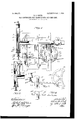
In the accompanying drawings, wherein like or similar reference characters indicate like or corresponding parts, Figure 1 is an elevation of my device, the valve and cooperating parts being in section to more clearly show the construction. Fig. 2 is a sectional view of a modified form of the main controlling-valve and by-pass. Fig. 3 is a slightly-modified form of operating mechanism adapted to be employed with the valve shown in Fig.1 or Fig. 2. Fig. 4 is a modified form of valve lever and connection.
In the preferred form of my device shown in the drawings the pipe 1 is provided for attaching my device to a gas-supply pipe in the usual or any preferred manner and may be provided with a stop-cock 2 or equivalent means to prevent the flow of gas into my de-' vice during the day or at other times when the light is not in use. The valve-tube 3 is connected to one end of the pipe 1, with one end connected to one or more burners 4: in any convenient manner, and its opposite end closed and provided with a small opening fitted with suitable packing to prevent the escape of gas, through which the stem 5 of the valve 6 projects. A valve-seat 7 is arranged in the tube 3 in such a position that when the valve 6 is seated the flow of gas from the pipe 1 to the burner 4 is preferably entirely prevented at the valve 6. When this occurs, the
light is extinguished, and to again relight the same when the valve 6 is opened a by-pass of the usual or any preferred construction is pro vided.
As shown in Fig. l, a by-pass is formed by providing a small opening 8 longitudinally of the stem 5 and an opening 9 through the tubular wall thus formed, so that gas within the tube 3 may pass at all times through the openings 9 and 8 beyond the valve 6 to the burners. To regulate the amount of gas escaping to the 'burners in the manner above described, a
threaded regulating valve 10 is provided, which may be operated by the small wheel or handle 11. Normally the valve6 is held open, with the stop 12 upon the stem 5 in contact with the interior of the cap at the closed end of the tube 3 by means of a spring 14, positioned between the cap of the tube 3 and the head 15 upon the stem 5. The head 15 is also employed to control the movement of the valve 6. As shown, a lever 16 is pivoted upon the frame 17 at 18, with one end in suitable engagement with the head 15 to close the valve 6 when operated and its opposite end in the path of a plurality of pins, teeth, or equivalent engaging means 19 upon a rotatable wheel 20. The wheel 20 is driven from any conven ient source by means of a belt 21 or equivalent means, and the pins 19 are arranged to produce the desired intervals oflight. If preferred, slots 22 may be formed in the rim of the wheel 20 and the pins 19 arranged to be clamped in any desired position in the slots, so that the alternation of light and darkness may be regulated to suit any requirements. Preferably a single pin is positioned in each slot 22; but it is evident that, if desired, any number of pins may be arranged in each slot,
or slots may be left without pins to secureany desired successions of light and darkness.
The lever 16 may be of any preferred form or construction. As shown in Fig. 4:, a substantially straight bar is provided and pivotally secured to the frame 17 at a fixed point 18. In this form it is evident that the time during which the valve 6 is held entirely closed must of necessity be short, as the pins 19'must slip off the end and release the lever practically as soon as the valve is closed, and there is no convenient means to adjust the mechanism to allow for wear. In the form shown in Fig. 3 these difiiculties are partially overcome by providing the curved extension 23 upon the lever 16 and by providing means for adthe pivotal support 18 consists, preferably, of
a slide 24, arranged to be vertically movable upon the frame 17 with the support 18 attached to the slide. Any convenient means may be provided to maintain the slide 24 in its adjusted position upon the frame. In this arrangement the position of the slide is very important, as if it is not high enough the valve 6 will not be entirely closed, and if it is too high the machine may be damaged by too forcibly closing the valve.
In the form shown in Fig. 1 a two-part lever 16 is shown pivotally connected upon the pivotal support 18, although it is evident that the pivotal connection between the two parts ofthe lever is not necessarily so positioned. A stop 25 is provided upon one part of the lever to limit the relative positions of the parts in one direction, and a spring 26 is provided to resiliently maintain the movable member against the stop. The extension 23 and slide 24 are provided the same as in Fig. 3, ex-
cept that a screw 27 is provided to assist in adjusting the position of the slide. In this construction preferably the slide 24 is so positioned that the lever 16 is depressed by the pins 19 more than suflicient to close the valve, the spring 26 holding the valve 6 to its seat and permitting the movable part of the lever 16 to leave the stop temporarily during the period the lever is so depressed. This con struction permits of considerable latitude in positioning the slide 24 and also allows for inaccuracy and wear in the wheel 20, pins19, and lever 16, and is my preferred construction, the forms shown in Figs. 3 and 4 being merely cheap and inferior substitutes for the form shown in Fig. 1.
In Fig. 2 a modified arrangement of a bypass is shown, in which the pipes 28 and 29 are connected and provided with a valve 30, the pipe28 being connected to the pipe 1 and the pipe 29 to the tube 3 above the valve-seat, in which case the stem 5 of the valve 6 is made solid, as shown, the action in all respects being the same as previously described.
In the drawings a simple and common form of burner 4 is shown; but it is obvious that any number or form of burners may be employed or any form of mantle, chimney, or other device adapted to produce a satisfactory and economical light.
Having thus described my in'i 'n'ovement, it is obvious that various immaterial modifications may be made in my device without departingfrom the spirit of my invention. Hence I do not wish to be understood as limiting myself to the exact form and construction shown.
What I claim as new, and desire to secure by Letters Patent, is-
1. Adevice of the kind described, comprising a tube, a valve controlling the opening in said tube and projecting therefrom, and means for connecting said tube in the supply-pipe to a gas-light, in combination with a rotatable wheel and means operated by said wheel for engaging the projecting portion of said valve to operate the same to control the supply of gas to said light, and means for rotating said wheel.
2. A device of the kind described, comprising a tube, a valve controlling the opening in said tube and projecting therefrom, and means for connecting said tube in the supply-pipe to a gas-light, in combination with a lever arranged to engage the projecting portion of said valve to operate the same, a rotatable wheel provided with means for periodically engaging said lever, and means for rotating said .wheel.
3. A device of the kind described, comprising a tube, a valve controlling the opening in said tube, and means for connecting said tube in the supply-pipe to a gas-light, in combination with a lever adapted to operate said valve, a curved extension formed upon one end of said lever, and a rotatable wheel provided with means for periodically engaging said lever near said extension to operate said valve, and means for rotating said wheel.
4. A device of the kind described, comprising a tube, a valve controlling the opening in said tube, and means for connecting said tube in the supply-pipe to a gas-light, in combination with a lever arranged to operate said valve, a rotatable wheel provided with means for periodically engaging said lever to operate said valve, means forrotating said wheel, and means for adjusting the pivotal support of saidlever to control the operation of said valve.
5. A device of the kind described, comprising a tube, a valve controlling the opening in said tube, and means for connecting said tube in the supply-pipe to a gas-light, in combination with a two-part lever arranged to operate said valve, the parts of said lever being pivotally connected, a stop to limit the relative movement of the lever parts and a spring tending to normally hold said movable part against said stop, a rotatable wheel provided with means for periodically engaging said lever to operate said valve, and means for rotating said wheel.
6. A device of the kind described, comprising a tube, a valve controlling the opening in said tube, and means for connecting said tube in the supply-pipe to a gas-light, in combination witha lever adapted to operate said valve, a curved extension formed upon one end of IIO said lever, a rotatable wheel provided with means for periodically engaging said lever pivotally connected, a stop to limit the relative movement of said lever parts in one direction, a spring tending to normally hold said movable part against said stop, and a curved extension formed at one end of said lever, a rotatable wheel provided with means for periodically engaging said lever near said extension to operate said valve, and means for rotating said Wheel.
8. A device of the kind described, comprising a tube, a valve controlling the opening in said tube, and means for connecting said tube in the supply-pipe to a gas-light, in combination with a two-part lever arranged to operate said valve, the parts of said lever being pivotally connected, a stop to limit the relative movement of said lever parts in one direction, a spring tending to normally hold said movable part against said stop, and a curved extension formed upon one end of said lever a rotatable wheel provided with means for periodically engaging said lever near said extension to operate said valve, means for rotating said wheel, and means for adjusting the pivotal support of said lever to control the operation of said valve.
9. A device of the kind described, comprising a tube, a valve, resiliently maintained at one limit of its movement,controlling the opening in said tube and means for connecting said tube in the supply-pipe to a gas-light, in combination With'a lever arranged to move said valve to the opposite limit of its movement, a rotatable wheel provided with means for periodically engaging said lever to operate said valve, and means for rotating said wheel.
10. A device of the kind described, comprising a tube, a valve resiliently maintained at onelimit ofits movement,controlling the opening in said tube, and means for connecting said tube in a supply-pipe to a gas-light, in combination with a lever arranged to move said valve to the opposite limit of its movement, a curved extension formed upon one end of said lever, and a rotatable Wheel provided with means for periodically engaging said lever near said extension to operate said valve, and means for rotating. said Wheel.
11. Adevice of the kind described, comprising a tube, a valve controlling the opening in said tube, a spring arranged to normally hold said valve open, and means for connecting said bination with a lever arranged to close said valve, a rotatable wheel provided with means for periodically engaging said valve to operate said valve, and means for rotating said Wheel.
12. Adevice of the kind described, comprising a tube, a valve controlling the opening in said tube and projecting laterally therefrom, and means for connecting said tube in the supply-pipe of a gas-light, in combination With a lever arranged-to engage said projecting part to'operate said valve, a rotatable Wheel provided with laterally-projecting pins in its rim for periodically engaging said lever, to operate said valve, and means for rotating said wheel.
13. Adevice of the kind described, comprising a tube, a valve controlling the opening in said tube, and means for connecting said tube in the supply-pipe to a gas-light, in combination with a lever arranged to operate said valve, a rotatable wheel having concentric slots formed in its rim, laterally-projecting pins adjustably positioned in said slot for periodically engaging said lever to operate said valve, and means for rotating said wheel.
14. Adevice of the kind described, comprising a tube, a valve controlling the opening in said tube, and means for connecting said tube in the supply-pipe to a gas-light, in combina- 5 tion with a lever adapted to operate said valve, a curved extension formed upon one end of said lever, a rotatable Wheel having concentric slots formed in its-rim, laterally-projecting pins adjustably positioned in said slots for periodically engaging said lever near said extension to operate said valve, and means for rotating said wheel.
15. A device of the kind described, comprising a tube, a valve controlling the opening in said tube, and means for connecting said tube in the supply-pipe to a gas-light, in combination with a lever arranged to operate said valve, a rotatable wheel having concentric slots formed in its rim, laterally-projecting pins adjustably positioned in said slots for periodically engaging said lever to operate said valve, and means for rotating said Wheel, and means for adjusting the pivotal support of said lever to control the operation of said valve.
16. A device of thekind described, comprising a tube, a valve controlling the opening in said tube, and means for connecting said tube in the supply-pipe to a gas-light, in combination With a two-part lever arranged to operate said valve, the' parts of said lever being pivotally connected, a stop to limit the relative movement of the lever parts, and a spring tending to normally hold said movable parts against said stop, a rotatable wheel having concentric slots in its rim, and laterally-projecting pins adjustably positioned within said slots for periodically engaging said lever to operate said valve, and means for rotating tube in the supply-pipe to a gas-light, in comsaid Wheel.
17. A device of thekind described, comprising a tube, a .valve projecting longitudinally from said tube and controlling the opening therein, a by-pass arranged to permit the passage of gas by said valve, means to control the passage through said by-pass, and means for connecting said tube in the supply-pipe of a gas-light, in combination with a rotatable wheel and means operated by said wheel for engaging said projecting part to operate said valve to control the supply of said gas to said light.
18. Adevice of the kind described, comprising a tube, a valve controlling the opening in said tube, a by-pass arranged to permit the passage of gas by said valve, means to control the passage through said by-pass, and means for connecting said tube in the supplypipe to a gas-light, in combination with a lever arranged to operate said valve. a rotatable wheel provided with means for periodically engaging said lever to operate said valve, means for rotating said wheel and means for adjusting the pivotal support of said lever to control the operation of said valve.
19. A device of the kind described, comprising a tube, a valve controlling the opening in said tube, a by-pass arranged to permit the passage of gas by said valve, means to control the passage through said by-pass, and means for connecting said tube in the supplypipe to a gas-light, in combination with a twopart lever arranged to operate said valve, the parts of said lever being pivotally connected, a stop to limit the relative movement of the lever parts and a spring tending to normally hold said movable part in contact with said stop, a rotatable wheel provided with means for periodically engaging said lever to operate said valve, and means 'for rotating said wheel.
20. A device of the kind described, comprising a tube, a'valve controlling the opening in said tube, a by-pass arranged. to permit the passage of gas by said valve means to control the passage of gas through said by-pass, and means for connecting said tube in the supplypipe to a gas-light, in combination with a lever adapted to operate said valve, a curved extension formed upon one end of said lever, a rotatable wheel provided with means for periodically engaging said lever near said extension to operate said valve, means for rotating said wheel, and means for adjusting the pivotal support of said lever to control the operation of said valve.
21. A device of the kind described, comprising a tube, avalve controlling the opening in said tube, a by-pass arranged to permit the passage of gas by said valve, means to control the passage through said valve, and means for connecting said tube in the supply-pipe to a gas-light, in combination with a lever adapted to operate said valve, a curved extension formed upon one end of said lever, a rotatable wheel provided with means for periodically engaging said lever near said extension to operate said valve, means for rotating said wheel, and means for adjusting the pivotal support of said lever to control the operation of said valve.
22. A device of the kind described, comprising a tube, a valve for controlling the opening in said tube, a by-pass arranged to permit the passage of gas by said valve, means to control the passage through said by-pass, and means for connecting said tube in the supplypipe to a gas-light, in combination with a lever arranged to operate said valve, a rotatable wheel having concentric slots formed in its rim, and laterally-projecting pins adjustably positioned in said slots, for periodically engaging said lever to operate said valve, and means for rotating said wheel.
23. A device of the kind described, comprising a tube, a valve controlling the opening in said tube, a spring arranged to normally hold said valve open, a by-pass arranged to permit the passage of gas by said valve, means to control the passage through said by-pass, and means for connecting said tube in the supplypipe to a gas-light, in combination with a lever arranged to close said valve, a rotatable wheel provided with concentric slots in its rim, and laterally-projecting pins ad justably positioned Within said slots for periodically engaging said lever to operate said valve, means for rotating said wheel and means for adjusting the pivotal support of said lever to control the operation of said valve.
24:. Adevice of the kind described, comprising a tube, a valve controlling the opening in said tube, a spring to normallyhold said valve open, a by-pass arranged to permit the passage of gas by said valve, means to control the passage through said by-pass, and means for connectingsaid tube in the supply-pipe to a gas-light, in combination with a two-part lever arranged to close said valve, the parts of said lever being pivotally connected, a stop to limit the relative movement of said parts in one direction, a spring tending to normally hold said movable part against said stop, and a curved extension formed at one end of said lever, a rotatable wheel provided with concentric slots in its rim, and laterally-projecting pins adjustably positioned in said slots for periodically engaging said lever near said extension to operate said valve, means for rotating said wheel, and means for adjusting the pivotal support of said lever to control the operation of said valve.
1n testimony whereof I have hereunto signed my name in the presence of two (2) subscribing witnesses.
ROBERT o. ROEHL.
\Vitnesses:
ROY WV. HILL, CHARLES l. COBB.
Priority Applications (1)
| Application Number | Priority Date | Filing Date | Title |
|---|---|---|---|
| US1905248622 US809077A (en) | 1905-03-06 | 1905-03-06 | Gas-controller for flash-lights and the like. |
Applications Claiming Priority (1)
| Application Number | Priority Date | Filing Date | Title |
|---|---|---|---|
| US1905248622 US809077A (en) | 1905-03-06 | 1905-03-06 | Gas-controller for flash-lights and the like. |
Publications (1)
| Publication Number | Publication Date |
|---|---|
| US809077A true US809077A (en) | 1906-01-02 |
Family
ID=2877558
Family Applications (1)
| Application Number | Title | Priority Date | Filing Date |
|---|---|---|---|
| US1905248622 Expired - Lifetime US809077A (en) | 1905-03-06 | 1905-03-06 | Gas-controller for flash-lights and the like. |
Country Status (1)
| Country | Link |
|---|---|
| US (1) | US809077A (en) |
Cited By (2)
| Publication number | Priority date | Publication date | Assignee | Title |
|---|---|---|---|---|
| US2685891A (en) * | 1948-06-07 | 1954-08-10 | August L Segelhorst | Automatic fluid control means |
| US2819799A (en) * | 1955-03-30 | 1958-01-14 | Wilkerson Corp | Low pressure drain valve |
-
1905
- 1905-03-06 US US1905248622 patent/US809077A/en not_active Expired - Lifetime
Cited By (2)
| Publication number | Priority date | Publication date | Assignee | Title |
|---|---|---|---|---|
| US2685891A (en) * | 1948-06-07 | 1954-08-10 | August L Segelhorst | Automatic fluid control means |
| US2819799A (en) * | 1955-03-30 | 1958-01-14 | Wilkerson Corp | Low pressure drain valve |
Similar Documents
| Publication | Publication Date | Title |
|---|---|---|
| US809077A (en) | Gas-controller for flash-lights and the like. | |
| US431387A (en) | Half to the smith | |
| US1272263A (en) | Atmospheric gas-burner. | |
| US1141503A (en) | Controller-cam device. | |
| US1072998A (en) | Automatic gas lighting and extinguishing mechanism. | |
| US672990A (en) | Automatic gas cut-off. | |
| US1003001A (en) | Valve for gas-lamps. | |
| US815179A (en) | Regulating-valve for gas-burners. | |
| US634856A (en) | Time gas lighting or extinguishing mechanism. | |
| US107105A (en) | Improvement in apparatus for lighting gas by electricity | |
| US1152214A (en) | Blow-torch. | |
| US522601A (en) | Gas cut-off device | |
| US333215A (en) | Paul h | |
| US722306A (en) | Gas-lamp. | |
| US922666A (en) | Attachment for gas stoves, lamps, &c. | |
| US717482A (en) | Gas incandescent lamp. | |
| US645168A (en) | Automatic cut-off pilot-burner. | |
| US873880A (en) | Gas-burner. | |
| US861182A (en) | Gas-lamp. | |
| US1092686A (en) | Controlling device for gas-burners. | |
| US343282A (en) | James f | |
| US1059873A (en) | Automatic cut-off for gas-burners. | |
| US515759A (en) | Lighting device for gas-burners | |
| US1031013A (en) | Incandescent gas-lamp. | |
| US1286937A (en) | Gas supply and regulating valve for inverted gas-burners. |