US809069A - Doweling-machine. - Google Patents
Doweling-machine. Download PDFInfo
- Publication number
- US809069A US809069A US25965705A US1905259657A US809069A US 809069 A US809069 A US 809069A US 25965705 A US25965705 A US 25965705A US 1905259657 A US1905259657 A US 1905259657A US 809069 A US809069 A US 809069A
- Authority
- US
- United States
- Prior art keywords
- block
- drill
- machine
- plate
- gage
- Prior art date
- Legal status (The legal status is an assumption and is not a legal conclusion. Google has not performed a legal analysis and makes no representation as to the accuracy of the status listed.)
- Expired - Lifetime
Links
- 239000000463 material Substances 0.000 description 20
- 238000010276 construction Methods 0.000 description 3
- 238000005259 measurement Methods 0.000 description 1
- 238000012986 modification Methods 0.000 description 1
- 230000004048 modification Effects 0.000 description 1
- 230000000630 rising effect Effects 0.000 description 1
- 239000002023 wood Substances 0.000 description 1
Images
Classifications
-
- B—PERFORMING OPERATIONS; TRANSPORTING
- B23—MACHINE TOOLS; METAL-WORKING NOT OTHERWISE PROVIDED FOR
- B23B—TURNING; BORING
- B23B47/00—Constructional features of components specially designed for boring or drilling machines; Accessories therefor
- B23B47/28—Drill jigs for workpieces
-
- Y—GENERAL TAGGING OF NEW TECHNOLOGICAL DEVELOPMENTS; GENERAL TAGGING OF CROSS-SECTIONAL TECHNOLOGIES SPANNING OVER SEVERAL SECTIONS OF THE IPC; TECHNICAL SUBJECTS COVERED BY FORMER USPC CROSS-REFERENCE ART COLLECTIONS [XRACs] AND DIGESTS
- Y10—TECHNICAL SUBJECTS COVERED BY FORMER USPC
- Y10T—TECHNICAL SUBJECTS COVERED BY FORMER US CLASSIFICATION
- Y10T408/00—Cutting by use of rotating axially moving tool
- Y10T408/55—Cutting by use of rotating axially moving tool with work-engaging structure other than Tool or tool-support
- Y10T408/563—Work-gripping clamp
- Y10T408/5633—Adapted to coaxially grip round work
Definitions
- Myinvention relates to a new and useful improvement in doweling-machines, and has for its object to provide a machine which will act as a gage or adjustable gig, so that the holes in the two pieces of wood to be joined together can be bored accurately, so that a perfect joint will be made when the dowelpins enter said holes and the two pieces are joined together.
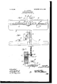
- Figure 1 is a plan view of my improved machine; Fig. 2, a rear elevation of the machine; Fig. 3, a cross-section through the center of the machine.
- A represents the base-plate, and upon this base-plate is arranged a strip B, having graduations thereon the same as a rule.
- O is the slot formed through the base-plate and extending parallel with the rule or longitudinally of the plate. This slot 0 is for the guides of the gage-block D, which gageblock is secured in place by the thumbscrew D. The material to be bored is adapted to abut against this gage-block.
- E is an ear extending outward from the top of the back E at the center and extends over the plate A.
- F is a screw threaded through the ear, and this screw has swiveled on the lower end a disk F, so that when the screw. is forced downward with the disk against the material operated upon it will form a clamp to hold the material in place, with one side of the material against the back E and the end against the gage-block D.
- G is a drill or auger guide which is in the form of an elongated block having different size circular openings G formed therethrough. This block is arranged in the center of the machine and adapted to slide between the guides E, arranged at the back of the device, the forward edge of the guide G coming flush with the front side of the back E.
- the H is a strip secured to the outside of one the lugs or guides E, and the side of the drill-guide G is curved, and in this groove fits one edge of the strip H, so as'to prevent the drill moving either forward or backward.
- the strip H is marked with graduations, as shown in Fig. 2, and straight lines can be drawn from the center of each of the holes G to the edge, so that the drill-guide can be set with any hole in any particular position.
- the thumb-screw I threaded through one of the lugs E and bearing against the drillguide block G, serves to hold the drill-guide in any position set.
- the block G is secured in place, and by placing the drill or or auger through the hole said drill or auger 9 is guided so that the hole formed will be perfectly straight and true, and the companion piece to be bored can then be placed in the machine and clamped in exactly the same place as the former piece, and whenthe hole is bored and the dowel-pins inserted in place a perfect joint is made, the edges of the material coming together accurately. It will thus be seen that the holes can be bored for dowel-pins without any complicated measurement and can be done very quickly, and besides when the holes are bored they are perfectly straight and true, so thatthe pieces will be in perfect alinement when joined together.
- a table upon which the material to be bored is adapted to lie, a vertical back formed with the table against which one edge of the material is adapted to be placed, a movable gage-block adapted to abut against the end of the material, means for clamping the material downward upon the table, a vertical sliding drill-block arranged in the back of the device, said drill-block provided with different size openings formed therethrough, said openings to form a guide for the drill, and means for securing said block in any position placed, as and for the purpose specified.
- a plate upon which the material is adapted to rest a plate forming a back extending at right angles from the rearward edge of the first-named plate against which one edge of the material is adapted to lie, the bed-plate being provided with a longitudinal guideway, a gage-block adapted to slide in said longitudinal guideway and abut against the end of the material, means for securing said gage-b1ock in any position placed, means for clamping the material downward upon the bed-plate, two vertical lu 's extending rearward from the back, a drilI-block adapted to slide vertically between said lugs, said drill- 4o block provided with lateral openings of different size formed therethrough from the front to the rear, said openings adapted to form guides for the drill, and means for securing said drill-block in any position placed, as and for the purpose specified.
- a bed plate having graduations marked thereon, said bed-plate provided with a longitudinal slot, a gage-block adapted to slide in said slot, means for securing said gageblock in place, a back rising at right angles to the bed-plate against which one edge of the material is adapted to rest, an ear extending forward from the upper end of the back, a clamp-screw threaded through said ear and adapted-to be forced downward upon the material, a drill-guide block adapted to slide vertically in the back, the forward edge of the drill-block being flush with the front face of the back, said drill-block being provided with different size holes bored therethrough from the front to the back, said holes being arranged one above the other, graduations arranged alongside of the drillblock to enable the block to be moved so that any one hole can be brought to a certain point, and means for securing the block in png position set, as and for the purpose speci- 1e
Landscapes
- Engineering & Computer Science (AREA)
- Mechanical Engineering (AREA)
- Earth Drilling (AREA)
Description
PATENTED JAN. 2, 1906.
3. L. LOVETT. v DOWELING MACHINE.
AYPLIOATION FILED MAY 10, 1905- UNITE D STATES PATENT OFFIOE.
DOWELlNG-IVIACHINE.
Specification of Letters Patent.
Patented Jan. 2, 19b 6.
Application filed May 10, 1905 Serial No. 259,657.
To (all whom, it 1 1 147 concern:
Be it known that I, JAMES L. LovETT, a citizen of the United States, residing at New London, county of Chester, and State of Pennsylvania, have invented a certain new and useful Improvement in Doweling-Machines, of which the following is a specification.
Myinvention relates to a new and useful improvement in doweling-machines, and has for its object to provide a machine which will act as a gage or adjustable gig, so that the holes in the two pieces of wood to be joined together can be bored accurately, so that a perfect joint will be made when the dowelpins enter said holes and the two pieces are joined together.
With these ends in view this invention consists in the details of construction and combination of elements hereinafter set forth and then specifically designated by the claims.
In order that those skilled in the art to which this invention appertains may understand how to make and use the same, the construction and operation will now be described in detail, referring to the accompanying drawings, forming a part of this specification, in which Figure 1 is a plan view of my improved machine; Fig. 2, a rear elevation of the machine; Fig. 3, a cross-section through the center of the machine.
A represents the base-plate, and upon this base-plate is arranged a strip B, having graduations thereon the same as a rule.
O is the slot formed through the base-plate and extending parallel with the rule or longitudinally of the plate. This slot 0 is for the guides of the gage-block D, which gageblock is secured in place by the thumbscrew D. The material to be bored is adapted to abut against this gage-block.
E is the back of the machine, which rises at right angles to the plate A and forms a straight edge, against which the material is adapted to be placed.
E is an ear extending outward from the top of the back E at the center and extends over the plate A.
F is a screw threaded through the ear, and this screw has swiveled on the lower end a disk F, so that when the screw. is forced downward with the disk against the material operated upon it will form a clamp to hold the material in place, with one side of the material against the back E and the end against the gage-block D.
G is a drill or auger guide which is in the form of an elongated block having different size circular openings G formed therethrough. This block is arranged in the center of the machine and adapted to slide between the guides E, arranged at the back of the device, the forward edge of the guide G coming flush with the front side of the back E.
H is a strip secured to the outside of one the lugs or guides E, and the side of the drill-guide G is curved, and in this groove fits one edge of the strip H, so as'to prevent the drill moving either forward or backward. The strip H is marked with graduations, as shown in Fig. 2, and straight lines can be drawn from the center of each of the holes G to the edge, so that the drill-guide can be set with any hole in any particular position. The thumb-screw I, threaded through one of the lugs E and bearing against the drillguide block G, serves to hold the drill-guide in any position set.
In operation when it is desired to bore the holes for dowel-pins in two pieces to be joined together it is first determined where the dowel-pins shall be placed. Then one piece of the material is secured in the machine, the gage-block D being moved until the point where the dowel-pin is to be inserted is directly behind the center of the block G. Then by screwing down the clamp F the material is held in this position. Then the block is moved vertically in its guideway until the proper size hole is brought to the proper place upon the material. Then the block G is secured in place, and by placing the drill or or auger through the hole said drill or auger 9 is guided so that the hole formed will be perfectly straight and true, and the companion piece to be bored can then be placed in the machine and clamped in exactly the same place as the former piece, and whenthe hole is bored and the dowel-pins inserted in place a perfect joint is made, the edges of the material coming together accurately. It will thus be seen that the holes can be bored for dowel-pins without any complicated measurement and can be done very quickly, and besides when the holes are bored they are perfectly straight and true, so thatthe pieces will be in perfect alinement when joined together.
Of course any suitable means could be used for clamping the material in place, or any suitable means could be'used for guiding the drill-block G and securing the same in place orfor securing the gage-block Din place. Therefore I do not wish to be limited to the exact construction here shown, as slight modifications could be made without departing from the spirit of the invention.
Having thus fully described my invention, what I claim as new and useful is 1. In a machine of the character described, a table upon which the material to be bored is adapted to lie, a vertical back formed with the table against which one edge of the material is adapted to be placed, a movable gage-block adapted to abut against the end of the material, means for clamping the material downward upon the table, a vertical sliding drill-block arranged in the back of the device, said drill-block provided with different size openings formed therethrough, said openings to form a guide for the drill, and means for securing said block in any position placed, as and for the purpose specified.
2. In a device of the character described, a plate upon which the material is adapted to rest, a plate forming a back extending at right angles from the rearward edge of the first-named plate against which one edge of the material is adapted to lie, the bed-plate being provided with a longitudinal guideway, a gage-block adapted to slide in said longitudinal guideway and abut against the end of the material, means for securing said gage-b1ock in any position placed, means for clamping the material downward upon the bed-plate, two vertical lu 's extending rearward from the back, a drilI-block adapted to slide vertically between said lugs, said drill- 4o block provided with lateral openings of different size formed therethrough from the front to the rear, said openings adapted to form guides for the drill, and means for securing said drill-block in any position placed, as and for the purpose specified.
3. In a device of the character described, a bed plate having graduations marked thereon, said bed-plate provided with a longitudinal slot, a gage-block adapted to slide in said slot, means for securing said gageblock in place, a back rising at right angles to the bed-plate against which one edge of the material is adapted to rest, an ear extending forward from the upper end of the back, a clamp-screw threaded through said ear and adapted-to be forced downward upon the material, a drill-guide block adapted to slide vertically in the back, the forward edge of the drill-block being flush with the front face of the back, said drill-block being provided with different size holes bored therethrough from the front to the back, said holes being arranged one above the other, graduations arranged alongside of the drillblock to enable the block to be moved so that any one hole can be brought to a certain point, and means for securing the block in png position set, as and for the purpose speci- 1e In testimony whereof I have hereunto affixed my signature in the presence of two subscribing witnesses.
JAMES L. LOVETT.
Witnesses J AMES M. SnoPE, WM. JONES.
Priority Applications (1)
| Application Number | Priority Date | Filing Date | Title |
|---|---|---|---|
| US25965705A US809069A (en) | 1905-05-10 | 1905-05-10 | Doweling-machine. |
Applications Claiming Priority (1)
| Application Number | Priority Date | Filing Date | Title |
|---|---|---|---|
| US25965705A US809069A (en) | 1905-05-10 | 1905-05-10 | Doweling-machine. |
Publications (1)
| Publication Number | Publication Date |
|---|---|
| US809069A true US809069A (en) | 1906-01-02 |
Family
ID=2877550
Family Applications (1)
| Application Number | Title | Priority Date | Filing Date |
|---|---|---|---|
| US25965705A Expired - Lifetime US809069A (en) | 1905-05-10 | 1905-05-10 | Doweling-machine. |
Country Status (1)
| Country | Link |
|---|---|
| US (1) | US809069A (en) |
Cited By (11)
| Publication number | Priority date | Publication date | Assignee | Title |
|---|---|---|---|---|
| US2428730A (en) * | 1944-04-13 | 1947-10-07 | Stanley Robert Pearce | Gauging device for use in positioning, marking, and holding timber and for guiding the bit whilst dowel holes are bored |
| US2439008A (en) * | 1945-06-05 | 1948-04-06 | Thomas E Meade | Drill stand and gauge |
| US2497733A (en) * | 1948-04-17 | 1950-02-14 | Joseph N Kebour | Precision layout gauge for drill guides |
| US2522400A (en) * | 1949-11-15 | 1950-09-12 | Gen Hardware Mfg Co Inc | Doweling jig |
| US2556131A (en) * | 1948-09-22 | 1951-06-05 | Wolfson Joel | Drill vise and jig |
| US2583283A (en) * | 1947-02-11 | 1952-01-22 | Stanley Works | Doweling jig |
| US2602238A (en) * | 1949-04-27 | 1952-07-08 | Clifton E Wellman | Boring jig or drill guide |
| US2740308A (en) * | 1953-03-27 | 1956-04-03 | Charles M Blanchard | Dowelling device |
| US2796778A (en) * | 1955-09-22 | 1957-06-25 | Julian W Hernandez | Doweling jig |
| US2928441A (en) * | 1957-04-18 | 1960-03-15 | Benjamin J Farrow | Dowel-pin hole-boring jig |
| US2930263A (en) * | 1957-03-21 | 1960-03-29 | Jones Eurgain | Dowel jigs |
-
1905
- 1905-05-10 US US25965705A patent/US809069A/en not_active Expired - Lifetime
Cited By (11)
| Publication number | Priority date | Publication date | Assignee | Title |
|---|---|---|---|---|
| US2428730A (en) * | 1944-04-13 | 1947-10-07 | Stanley Robert Pearce | Gauging device for use in positioning, marking, and holding timber and for guiding the bit whilst dowel holes are bored |
| US2439008A (en) * | 1945-06-05 | 1948-04-06 | Thomas E Meade | Drill stand and gauge |
| US2583283A (en) * | 1947-02-11 | 1952-01-22 | Stanley Works | Doweling jig |
| US2497733A (en) * | 1948-04-17 | 1950-02-14 | Joseph N Kebour | Precision layout gauge for drill guides |
| US2556131A (en) * | 1948-09-22 | 1951-06-05 | Wolfson Joel | Drill vise and jig |
| US2602238A (en) * | 1949-04-27 | 1952-07-08 | Clifton E Wellman | Boring jig or drill guide |
| US2522400A (en) * | 1949-11-15 | 1950-09-12 | Gen Hardware Mfg Co Inc | Doweling jig |
| US2740308A (en) * | 1953-03-27 | 1956-04-03 | Charles M Blanchard | Dowelling device |
| US2796778A (en) * | 1955-09-22 | 1957-06-25 | Julian W Hernandez | Doweling jig |
| US2930263A (en) * | 1957-03-21 | 1960-03-29 | Jones Eurgain | Dowel jigs |
| US2928441A (en) * | 1957-04-18 | 1960-03-15 | Benjamin J Farrow | Dowel-pin hole-boring jig |
Similar Documents
| Publication | Publication Date | Title |
|---|---|---|
| US809069A (en) | Doweling-machine. | |
| US550767A (en) | Scher | |
| US1894010A (en) | Work-holding means for gauges | |
| US750449A (en) | Depth-scale | |
| US1205687A (en) | Measuring instrument. | |
| US1161479A (en) | Boring-tool-guiding apparatus. | |
| US917488A (en) | Jig for braces and bits. | |
| US1016594A (en) | Clamp and gage. | |
| US706392A (en) | Hand doweling-gage. | |
| US1153841A (en) | Doweling device. | |
| US581811A (en) | James coyle | |
| US1097153A (en) | Doweling device. | |
| US816424A (en) | Adjustable fence for saws. | |
| US1370683A (en) | Clamping device | |
| US668695A (en) | Drill-vise and attachment for same. | |
| US1438562A (en) | Doweling machine | |
| US2928441A (en) | Dowel-pin hole-boring jig | |
| US2167082A (en) | Tenon cutter | |
| US727986A (en) | Clamp. | |
| US20150075674A1 (en) | Apparatus for Forming Dovetail and Box Joints | |
| US1147063A (en) | Saw-guide. | |
| US503045A (en) | Marker for window-frames | |
| US666631A (en) | Clamp for routing-machines. | |
| US1028584A (en) | Clamp for use in the production of screen and window frames, doors, &c. | |
| US699664A (en) | Flooring-gage. |