US809041A - Centrifugal pulp-screen. - Google Patents
Centrifugal pulp-screen. Download PDFInfo
- Publication number
- US809041A US809041A US27634505A US1905276345A US809041A US 809041 A US809041 A US 809041A US 27634505 A US27634505 A US 27634505A US 1905276345 A US1905276345 A US 1905276345A US 809041 A US809041 A US 809041A
- Authority
- US
- United States
- Prior art keywords
- screen
- blades
- stock
- opening
- plates
- Prior art date
- Legal status (The legal status is an assumption and is not a legal conclusion. Google has not performed a legal analysis and makes no representation as to the accuracy of the status listed.)
- Expired - Lifetime
Links
- 239000002184 metal Substances 0.000 description 13
- 238000001816 cooling Methods 0.000 description 10
- XLYOFNOQVPJJNP-UHFFFAOYSA-N water Substances O XLYOFNOQVPJJNP-UHFFFAOYSA-N 0.000 description 9
- 230000001105 regulatory effect Effects 0.000 description 5
- 239000000463 material Substances 0.000 description 3
- 241000183290 Scleropages leichardti Species 0.000 description 2
- 238000002474 experimental method Methods 0.000 description 2
- 101100400378 Mus musculus Marveld2 gene Proteins 0.000 description 1
- 229940000425 combination drug Drugs 0.000 description 1
- 238000010276 construction Methods 0.000 description 1
- 238000011109 contamination Methods 0.000 description 1
- 239000007788 liquid Substances 0.000 description 1
- 239000002245 particle Substances 0.000 description 1
- 229920000136 polysorbate Polymers 0.000 description 1
- 230000000630 rising effect Effects 0.000 description 1
- 239000000126 substance Substances 0.000 description 1
- 238000005406 washing Methods 0.000 description 1
- 239000002699 waste material Substances 0.000 description 1
Images

Classifications
-
- D—TEXTILES; PAPER
- D21—PAPER-MAKING; PRODUCTION OF CELLULOSE
- D21D—TREATMENT OF THE MATERIALS BEFORE PASSING TO THE PAPER-MAKING MACHINE
- D21D5/00—Purification of the pulp suspension by mechanical means; Apparatus therefor
- D21D5/02—Straining or screening the pulp
- D21D5/023—Stationary screen-drums
- D21D5/026—Stationary screen-drums with rotating cleaning foils
Definitions
- the water-pipe 6 is provided with a valve 7 and terminates in a discharge-nozzle 8.
- This discharge-nozzle 8 is narrow in one di-. rection and of a maximum width in the other direction. (See Fig. 6.)
Landscapes
- Engineering & Computer Science (AREA)
- Mechanical Engineering (AREA)
- Paper (AREA)
Description
No. 309,041. PATENTED JAN. 2, 1906. J. H. BAKER, G. F. SHEVLIN & F. H. BAKER.
UENTRIFUGAL PULP SCREEN,
APPLICATION FILED .AUG.30,1905.
2 SHEETS-SHEET 1.
No. 809,041. PATENTBD JAN. 2, 1906. J. H. BAKER, G. F. SHEVLIN &: F. H. BAKER.
OENTRIFUGAL PULP SCREEN.
APPLICATION FILED AUG. 30, 1905.
2 SHEETS-SHEET 2.
.1101; .lloll UNITED STATES PATENT OFFICE.
JAMES H. BAKER, GEORGE F. SHEVLIN, AND FREDERICK H. BAKER, OF
SARATOGA SPRINGS, NEW YORK, ASSIGNORS TO BAKER AND SHEV- LIN COMPANY, OF SARATOGA SPRINGS, NEW YORK, A CORPORATION OF NEW YORK.
CENTRIFUGAL PULP-SCREEN.
devices we have found that stock would gather behind the blades of the beater-wheels and tend to throw the wheels out of balance. We have also found that the exitslots for the stock from the central receivingwell to the delivery portions of the beaterwheels would not answer for all grades of stock. It is sometimes necessary to obtain access to the interior of the machine for examination of the screen-plates, &c., and heretofore it has been necessary to partly dismantle the machine, certainly to remove one or more of the panels of the outer casing, We have also found it necessary to provide for the discharge of an increased volume of air from between the screen-plates and easing on the side of delivery of the good stock otherwise the pent-up pressure will seriously interfere with the full working of the screenplates. We have also found it necessary to provide improved means for delivering the stock to the centrifugal machine, mixing it with a regulatable quantity of water, and preventing the suction of air therewith to any appreciable extent because of the action of the beater-wheels.
In the machine of our present improvement we provide fillets which we place behind the blades of the beater-wheels and within the central receiving-well, so as to prevent the stock gathering behind the blades of the beater-wheels, and in this way we overcome any tendency to throw the wheels out of balance, and we provide adjacent to the exit of the central receiving-well adjustable blades which may be moved to increase or diminish the atmospheric pressure at the slot, so that the opening is suitable for the grade of stock passing through the centrifugal machine. In order that access may be obtained Specification of Letters Patent.
Application filed August 30, 1905. Serial No. 276,345.
Patented Jan. 2, 1906.
within the casing of the machine for the purpose of examining the screens, &c., we provide openings in the external casing with shutters or slide-plates that may be simply raised to obtain access within the casing. This obviates the necessity of dismantling the machine in any respect.
In Letters Patent granted to us, No. 686,962, November 19, 1901, we illustrated and described a device for relieving the pentup air-pressure between the casing and the screen-plates; but we have found by experience that this operates only to a certain extent, but not sufficient for the full operation of the machine, and we have therefore pro vided adjacent to the top trough for the good stock an opening for the discharge of air from the lower part of the annular chamber.
In our improved machine we provide devices for more perfectly and effectually delivering the stock to the centrifugal'pulpscreen, mixing it with a regulatable quantity of water, and passing the same from a receiving-vat into the machine, so as to avoid as far as possible the entrance of air into the machine to an appreciable extent.
The means for oiling and cooling the vertical shaft of our improved centrifugal pulpscreen were specifically shown and described in Letters Patent No. 738,513, of September 8, 1903. In the device of this patent a flange was shown extending around the oilreceptacle'to prevent foreign substances getting in and mixing with the oil to its detriment; but we have found by experiment that this shaft throws oiland it is likely to get out and be lost as well as to cause a spat-- tering that has to be cleaned up. In our present improved machine we have provided a flange that extends down within the oil vessel, so as to receive any oil thrown off from the oil-shaft and cause the same to return to the oil vessel.
All of these parts will hereinafter be more particularly described and claimed.
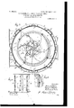
In the drawings, Figure 1 is a vertical section and partial elevation representing our complete improved pulp-screen. Fig. 2 is a vertical section and partial elevation, in larger size, of the oiling and cooling devices employed by us at the lower end of the revoluble shaft. Fig. 3 is a sectional plan about trifugal screen-plates, a pipe d being connectshaft Z) and receive the good stock and slivers.
tric to the other.
parts, so as to provide a firm structure, and
on the dotted line at a; of Fig. 1 and in larger I size. Fig. 4 is an elevation of a portion of the said receivingwell, showing the exit-slots and the means for adjusting the proportions of the same. Fi 5 is a vertical section about on the dotted fine y 'y, Fig. 3, and on a scale agreeing with Fig. 3; and Fig. 6 is an elevation, partially in section, of the water-discharge nozzle.
A platform or supporting structure a may be employed for thbed-support a of the machine, or the bed-support a may rest upon any suitable foundation. The vertical revoluble shaft 7) passes up centrally through the machine, with its lower end in the oiling and cooling step-bearing devices 1), preferably the same as that described and illustrated in our Letters Patent No. 738,513, and b is a pulley at the upper end of the vertical shaft 1). A number of standards 61?, secured to and risingfrom the bed-support (1., carry the major parts of the machine, among the first of which are the annular concentric cast-metal troughs c, d, which surround the vertical The outer metal trough c at one side is provided with a horizontal air-exit opening 0, and adjacent to this opening the bottom of the trough is removed and a lower dischargetrough c secured to the flanged edges of the trough c, and a tank 0 is secured to the sides of the troughs c and c, the air-opening 0 providing for the entrance of air to the annular chamber between the casing and the segmental screen-plates, while the good stock from the said annular chamber delivered into the trough c discharges into the trough cand from there into the tank 0 On the other side of the machine a portion of the bottom of the annular concentric cast-metal trough cl is removed and a trough d, fitting below the opening, serves as a discharge for the slivers which gather in the trough d within the cened to the trough d to carry the slivers away either as a waste product or to be again treated in other machines, if desired. We also connect the discharge water-pipe 26 from the water-chamber of the step to the sliver-trough of the screen to wash out the slivers as fast as they drop into the trough.
The upper outer edges of the annular concentric cast-metal troughs c d are flanged, and we provide ring-flanges e e, secured to these flanges and coming outside of and in turn secured to the segmental casing f, formed of panels, and the circular segmental screen-plates g, the one of which is concen- We .provide a cover-plate h, open in the center and in turn provided with ring-frames 2 3, secured thereto and coming outside of the upper ends of the segmental casingf and screen-plates g and in turn secured to said in the cover h are openings and perforated plates h to the annular chamber between the casingf and plates g for the relief of the pent-up air in said annular chamber and for washing the screen-plates, as described in Letters Patent heretofore granted to us, Nos. 693,215 and 735,444.
As shown in Fig. 3, we usually employ four panels or plates to the casing], between which are located hollow air-vent columns 9, as shown and described in our prior patent, No. 727,878, and to the sides of whichthe plates or panels forming the segmental casing f are secured. To obtain accessto the interior of this casing for any purpose whatsoever, we provide openings, preferably one in each panel, and around each opening place a frame f, the frames being so constructed with side slideways as to receive the verti- Cally-removable shutter f at the lower end of which is a loop-handle. As the said shutter slides and fits in recessed edges, none of the materials can escape from the annular chamber, said parts being liquid and pulp ti it.
g represents the circular segmental screenplates of the usual form and construction heretofore employed by us and described in our patents, said screen-plates rising from the flange which divides the troughs c d.
A cylinder 11, having an inletpipe 4, is secured to the cover 71., the same preferably having a flange passing down into the central opening of the cover and constructed with a cleaning-out opening 5 and hollow cover-inclosure i, having a deflector 4 as shown and described in our former patent,-. No. 727,878.
The water-pipe 6 is provided with a valve 7 and terminates in a discharge-nozzle 8. This discharge-nozzle 8 is narrow in one di-. rection and of a maximum width in the other direction. (See Fig. 6.)
9 represents a pipe for conveying along the paper-stock, in which is a valve 10.
Both the pipes 6 and 9 turn with bends from a horizontal to a vertical direction and enter the vat 11. This vat is provided with an opening 12 and sliding gate 14, and a pipe 13 connects the vat at the opening 12 with the pipe 4. It will be noticed that the lower end of the pipe 9 is Well down in the vat 11, and as the stock is delivered said end is probably immersed. Furthermore, this lower end of the pipe comes below the limits of the opening 12, while the discharge-nozzle 8 for the water is above this opening, so that the stock does not come into contact with the nozzle 8. In this vat the stock is received and as it enters is diluted by the water from the pipe 6 and nozzle 8, and the valves 7 and 10 provide for regulating the quantities of stock and water, so as to obtain the desired consistency of the material before it enters the pulp-screen; The height of the gate 14 may be regulated as desired; but it is preferable make the same below the level of the pulp in the vat, so as to prevent the suction of the machine drawing air into the same as far as possible.
The beater-wheels employed byus are similar to those in our copending application of November 5, 1904, Serial No. 231,503, and they comprise the hub k, having inclined flanges k 70 formed therewith. With these parts are also formed radial curved partitionwalls and flanges 16, 17, and 18, the flanges 16 and 17 being curved and theflanges 18 being vertical and radial. The diameter of the inclined flange k is slightly greater than the diameter of the inclined flange 7c.
We provide a top plate Z and flanges 19, and betwween the same and the inclined flanges are located the cylinder m and flanges m. The curved radial blades n are both within and without the cylinder m, and in the structure of the beater-wheels these blades are riveted to the flanges 16, 17, 18, and 19, as well as to the flanges m of the cylinder, so as to form a substantially integral structure, there being in the cylinder m adjacent to the convex-surfaces of the blades, slots 20. In connection with these slots 20, and as especially shown in Figs. 3 and 4, we provide adjacent blades 0. These overlie the outer surface of the cylinder m and are provided with slots through which pass screws into the cylinder, and by these blades 0 the size of the slots 20 can be readily regulated in proportion to the kinds of stock to be treated or its consistency. This adjustment can be effected by removing one panel of the outside casing and one section of screen-plates, this leaving the beater-wheels exposed and by turning all the adjustable blades 0 can be adjusted.
' The hub' la is shorter than the depth of the blades n. Consequently the portions of the blades within the cylinder m are curved over downward to meet the top of the hub, the cavity within the cylinder m and above the hub 16 being clear except for the shaft 1).
To prevent the stock gathering behind the blades of the beater-wheels, we provide fillets 1". These are shown in elevation in Fig. 1, in plan and section in one direction in Fig. 3, and in vertical section in Fig. 5. They are blades of peculiar form, the respective ends of which are bent at an inclination to the main portion, so that while the main portion extends at an angle across between the inner portion of the cylinder m and the inner surface of the blades the ends bend in to fill the angle and close up the cavity between said parts and thestraight parts of said fillets, so as to prevent the stock getting into the angles formed by the said cylinder and blades. These fillets are es pecially located at the upper part of the central well and reach down behind the blades to just above the hub 76, at which place occurs the lower inclined part of the fillet, and thus leaving the cylinder below this point and the top of the hub of full size for the more perfect performance of its functions, experiment having proved that the fillets are not required in the lower part of the well, where the most of the work is done in the centrifugal machine.
In Fig. 2 we have shown the oiling and cooling device for the steppedlower end of the vertical revoluble shaft 6. This substantially agrees with the structure shown and described in our Patent No. 738,513, of September 8, 1903, and we provide in connection with this device the cover it, having an outer annular flange t and an inner annular flange t Between these flanges the flange at the upper end of the oiling and cooling device, which forms a receptacle for the oil, is received. The outer flange t prevents the entrance into the oil of foreign matter or paper-stock, and the inner flange prevents the oil spattered by the revoluble shaft during its high speed from getting out of the oil vessel and returns it to the oil-receptacle, thus preventing a litter being made by the flying oil outside of the oil vessel, as well as preventing the contamination of the oil by foreign mate rials mixing with the same to its detriment.
We claim as our invention 1. In a centrifugal pulp-screen, the combination with the beater-wheels, of devices secured behind the blades of the beater-wheels and within the cylindrical portion and near the upper ends of the blades to prevent the stock gathering behind the blades.
2. In a centrifugal pulp-screen, the combination with the blades and cylindrical portions of the beater-wheels, of devices placed behind the blades and within the cylindrical part and near the upper part of the blades and extending across and filling the spaces behind the blades and means for attaching the same in place so as to ment of stock behind the blades.
3. In a centrifugal pulp-screen, the combination with the series of curved blades and the cylindrical portion bisecting the same and forming the beaterwheels, of fillets comprising plates of metal with bent ends extending across behind the blades and in the angle formed by said blades and cylinder with the end fitting in against the backs of the blades and surface of the cylinder, so as to prevent the stock gathering behind the blades.
4. Ina centrifugal pulp-screen, the combination with the blades and cylindrical portion forming the beater-wheels and in which cylindrical portion are exit-slots for the stock at the edges of and parallel with the said blades, of means for lessening the size of said slots as desired.
5. In a centrifugal pulp-screen, the combination with the blades and cylindrical portion forming'the beater-wheels and in which prevent the lodg gift cylindrical portion are exit-slots for the stock at the edges of and parallel with said blades, of blades slotted transversely and screws for attaching the same to the surface of the cylinder providing for an adjustable relation of the blades to the cylinder for varying the size of the slots.
6. In a centrifugal pulp-screen the combination with the circular segmental screenplates and the annular concentric cast-metal troughs, of the segmental casing of panels surrounding the screen-plates and provided with an opening of appreciable area, a frame surrounding said opening and forming a slideway and a shutter-plate within said frame and against the surface of said casing to close off the opening in the panel of the casing for providing access thereto by raising the shutterplate.
7. In a centrifugal pulp-screen, the combi nation with the circular segmental screenplates and the annular concentric cast-metal troughs, of the segmental casing of panels surrounding the screen-plates and provided with an opening of appreciable area, of a device having a slidable relation with said panels and adapted to cover the opening therein and a support therefor.
.8. In a centrifugal pulp-screen, the combination with the segmental casing and concentric circular segmental screen-plates within the same, of the annular concentric castmetal troughs, the one coming between the aforesaid parts at the base thereof and the other within the screen-plates, a dischargetrough connected with the inner of said concentric troughs and located below the same on one side of the machine, a discharge-trough opening into the outer of said cast-metal troughs and located beneath the same, and an exit-opening formed in the latter trough parallel to the exit-opening of the latter discharge-trough as an exit-opening for air from between the casing and the screenplates.
9. In a centrifugal pulp-screen, the combination with the segmental casing of panels and the circular segmental screenplates connected therewith and within the same and the annular concentric cast-metal troughs, the one between and the other within the said parts, of means located at the upper portion of the casing and screen-plates, between the panels of the segmental casing and also at one side of the outer cast-metal trough as exists for the confined air between said casing and screen-plates in the operation of the machine.
10. In a centrifugal pulp-screen, the combination with the segmental casin g f and circular screen-plates g, of the annular concentric cast-metal troughs e (Z, to which the aforesaid parts are connected, a curved. dischargetrough 0 below and opening into the trough c at one side of the machine and having an exit-opening therefrom and of the length of the said trough c and a parallel opening 0 at the side of the trough c as an exit for the air from between the casing and the screenplates.
1. 1. In a centrifugal pulp-screen, the combination with the segmental casingf and circular screen-plates g, of the annular concentric cast-metal troughs c d, to which the aforesaid parts are connected, a curved dischargetrough 0 below and opening into the trough c at one sideof the machine and having an exit-opening therefrom and of the length of the said trough c and a parallel opening 0 at the side of the trough c as an exit for the air from between the casing and the screen-plates, and a tank 0 fitted up against the dischargetrough c and the air-exit opening 0 of the trough c to receive the good stock in the operation of the machine.
12. In a centrifugal pulp-screen, the combil nation with a vertical revoluble shaft and a step-bearing for the lower end of the shaft and means for oiling and cooling the shaft at its bearing, of a cover to the oiling and cooling device provided with a downwardly-extending outer flange t and a second downwardly-extending inner flange i 13. In a centrifugal pulp-screen, the combination with a vertical revoluble shaft and a step-bearing for the lower end of the shaft and means for oiling and cooling the shaft at its bearing, of a device surrounding the shaft and extending over the oiling and cooling device and having 'parts associated therewith and acting at the same time to prevent foreign particles getting into the oiling and cooling device or oil spattered by the revolving shaft from getting out.
14. In a centrifugal pulp-screen, the combination with a vertical revoluble shaft and the beater-wheel, of an inlet-pipe for the stock to the beaterwheel, a vat and pipe connecting the same to said inlet-pipe, a pipe for introducing the stock into the vat, a pipe for water and a nozzle for admitting the water into the vat to mix with the stock and reduce its consistency, and a gate in the opening between said vat and pipe for regulating the extent of flow of the thinned stock to the machine.
15. In a centrifugal pulp-screen, the combination with a vertical revoluble shaft and the beater-wheel, of an inlet-pipe for the stock to the beater-wheel, a vat and pipe connecting the same to said inlet-pipe, a pipe for introducing the stock into the vat, a pipe for water and a nozzle for admitting the water into the vat to mix with the stock and reduce its consistency and a gate in the opening between said vat and pipe for regulating the extent of the flow of the thinned stock to the machine, the said nozzle being narrow in one direction and of at least the diameter of the pipe in the opposite direction and located above the lower end of the gate and the discharge-opening formed thereby and the lower end of the inlet-pipe for the stock below the normal position of the lower end of the gate and inn nation with the segmental oasingf and cirou- I 5 lar screen-plates g of the annular cast-metal trough 0 coming below and between the Vertioal planes thereof, and an air-exit opening 0 at one side of the trough c and in the same horizontal plane for the pent-up air from be- 20 tween the casing and screen-plates.
Signed by us this 2d day of August, 1905.
JAlWES H. BAKER. GEORGE F. SHEVLIN. FREDERICK H. BAKER. Witnesses:
CHARLES M. DAVISON, WM. OBRIER.
Priority Applications (1)
| Application Number | Priority Date | Filing Date | Title |
|---|---|---|---|
| US27634505A US809041A (en) | 1905-08-30 | 1905-08-30 | Centrifugal pulp-screen. |
Applications Claiming Priority (1)
| Application Number | Priority Date | Filing Date | Title |
|---|---|---|---|
| US27634505A US809041A (en) | 1905-08-30 | 1905-08-30 | Centrifugal pulp-screen. |
Publications (1)
| Publication Number | Publication Date |
|---|---|
| US809041A true US809041A (en) | 1906-01-02 |
Family
ID=2877522
Family Applications (1)
| Application Number | Title | Priority Date | Filing Date |
|---|---|---|---|
| US27634505A Expired - Lifetime US809041A (en) | 1905-08-30 | 1905-08-30 | Centrifugal pulp-screen. |
Country Status (1)
| Country | Link |
|---|---|
| US (1) | US809041A (en) |
-
1905
- 1905-08-30 US US27634505A patent/US809041A/en not_active Expired - Lifetime
Similar Documents
| Publication | Publication Date | Title |
|---|---|---|
| US3713536A (en) | Pressure pulp screen | |
| SU1192632A3 (en) | Revolving device for sorting mass with vertical pressure | |
| US2371837A (en) | Apparatus for pulping and screening papermaking materials | |
| US2324018A (en) | Flotation cell | |
| CA1316386C (en) | High-consistency pulp tower and method of discharging pulp from the tower | |
| US809041A (en) | Centrifugal pulp-screen. | |
| US2599202A (en) | Apparatus for washing and conditioning air | |
| US2312545A (en) | Centrifugal screening machine for paper stock and similar material | |
| US811930A (en) | Paper-pulp-assorting apparatus. | |
| US2908346A (en) | Apparatus for homogenizing and degasifying flowable materials | |
| US4902410A (en) | Interceptor for the continuous removal of solid matter from a mixture of solids and liquid | |
| US4642189A (en) | Rotary screen of the vertical pressure type having pulp stock feed at different axial positions on the screen | |
| US591645A (en) | Pulp-screen | |
| US483030A (en) | volstorf | |
| US1696354A (en) | Pulp-screening machine | |
| US1926402A (en) | Extractor | |
| US1179658A (en) | Agitating and settling tank. | |
| US1859827A (en) | Foam reducing apparatus | |
| US5271672A (en) | Apparatus having rotating arms and fluid outlet for treating and discharging a medium | |
| US931280A (en) | Centrifugal screen. | |
| US703682A (en) | Paper-pulp strainer. | |
| US1422251A (en) | Method of and apparatus for disintegrating paper stock | |
| US155152A (en) | Improvement in disintegrating apparatus for paper-pulp | |
| US1843791A (en) | Rotary pulp screen | |
| US721186A (en) | Centrifugal cream-separator. |