US8090308B2 - Continuous paper feed device, image forming apparatus, continuous paper feeding method and computer readable media storing program - Google Patents
Continuous paper feed device, image forming apparatus, continuous paper feeding method and computer readable media storing program Download PDFInfo
- Publication number
- US8090308B2 US8090308B2 US12/245,965 US24596508A US8090308B2 US 8090308 B2 US8090308 B2 US 8090308B2 US 24596508 A US24596508 A US 24596508A US 8090308 B2 US8090308 B2 US 8090308B2
- Authority
- US
- United States
- Prior art keywords
- paper
- slack
- continuous paper
- unit
- remaining amount
- Prior art date
- Legal status (The legal status is an assumption and is not a legal conclusion. Google has not performed a legal analysis and makes no representation as to the accuracy of the status listed.)
- Expired - Fee Related, expires
Links
Images


Classifications
-
- B—PERFORMING OPERATIONS; TRANSPORTING
- B65—CONVEYING; PACKING; STORING; HANDLING THIN OR FILAMENTARY MATERIAL
- B65H—HANDLING THIN OR FILAMENTARY MATERIAL, e.g. SHEETS, WEBS, CABLES
- B65H35/00—Delivering articles from cutting or line-perforating machines; Article or web delivery apparatus incorporating cutting or line-perforating devices, e.g. adhesive tape dispensers
- B65H35/04—Delivering articles from cutting or line-perforating machines; Article or web delivery apparatus incorporating cutting or line-perforating devices, e.g. adhesive tape dispensers from or with transverse cutters or perforators
-
- B—PERFORMING OPERATIONS; TRANSPORTING
- B65—CONVEYING; PACKING; STORING; HANDLING THIN OR FILAMENTARY MATERIAL
- B65H—HANDLING THIN OR FILAMENTARY MATERIAL, e.g. SHEETS, WEBS, CABLES
- B65H20/00—Advancing webs
- B65H20/30—Arrangements for accumulating surplus web
- B65H20/32—Arrangements for accumulating surplus web by making loops
-
- B—PERFORMING OPERATIONS; TRANSPORTING
- B65—CONVEYING; PACKING; STORING; HANDLING THIN OR FILAMENTARY MATERIAL
- B65H—HANDLING THIN OR FILAMENTARY MATERIAL, e.g. SHEETS, WEBS, CABLES
- B65H26/00—Warning or safety devices, e.g. automatic fault detectors, stop-motions, for web-advancing mechanisms
- B65H26/06—Warning or safety devices, e.g. automatic fault detectors, stop-motions, for web-advancing mechanisms responsive to predetermined lengths of webs
-
- B—PERFORMING OPERATIONS; TRANSPORTING
- B65—CONVEYING; PACKING; STORING; HANDLING THIN OR FILAMENTARY MATERIAL
- B65H—HANDLING THIN OR FILAMENTARY MATERIAL, e.g. SHEETS, WEBS, CABLES
- B65H2511/00—Dimensions; Position; Numbers; Identification; Occurrences
- B65H2511/10—Size; Dimensions
- B65H2511/11—Length
- B65H2511/112—Length of a loop, e.g. a free loop or a loop of dancer rollers
-
- B—PERFORMING OPERATIONS; TRANSPORTING
- B65—CONVEYING; PACKING; STORING; HANDLING THIN OR FILAMENTARY MATERIAL
- B65H—HANDLING THIN OR FILAMENTARY MATERIAL, e.g. SHEETS, WEBS, CABLES
- B65H2511/00—Dimensions; Position; Numbers; Identification; Occurrences
- B65H2511/30—Numbers, e.g. of windings or rotations
-
- B—PERFORMING OPERATIONS; TRANSPORTING
- B65—CONVEYING; PACKING; STORING; HANDLING THIN OR FILAMENTARY MATERIAL
- B65H—HANDLING THIN OR FILAMENTARY MATERIAL, e.g. SHEETS, WEBS, CABLES
- B65H2511/00—Dimensions; Position; Numbers; Identification; Occurrences
- B65H2511/40—Identification
- B65H2511/414—Identification of mode of operation
-
- B—PERFORMING OPERATIONS; TRANSPORTING
- B65—CONVEYING; PACKING; STORING; HANDLING THIN OR FILAMENTARY MATERIAL
- B65H—HANDLING THIN OR FILAMENTARY MATERIAL, e.g. SHEETS, WEBS, CABLES
- B65H2801/00—Application field
- B65H2801/03—Image reproduction devices
- B65H2801/06—Office-type machines, e.g. photocopiers
Definitions
- the present invention relates to a continuous paper feed device, an image forming apparatus, a continuous paper feeding method and a computer readable media storing program.
- a continuous paper feed device including a paper feed unit that feeds continuous paper to an image output part; a slack forming unit that forms a slack of continuous paper on a paper transport path through which the continuous paper is fed by the paper feed unit; a detecting unit that detects a remaining amount of continuous paper; a cutting unit that cuts the continuous paper; and a cutting controller that controls the cutting unit to cut the continuous paper during a time taken to tighten the slack formed by the slack forming unit, when paper more than a predefined value which has been set beforehand is transported, and if the remaining amount of paper detected by the detecting unit is equal to or more than a threshold value, the cutting controller performing one mode of control operation including reducing a length of a slack formed by the slack forming unit and transporting the continuous paper, followed by forming a slack again by the slack forming unit and cutting the continuous paper during a time taken to tighten the
- FIG. 1 is a diagram depicting a structure of an image forming apparatus 10 of an exemplary embodiment of the present invention
- FIG. 2 is a diagram showing a hardware structure of the image forming apparatus 10 of an exemplary embodiment of the present invention
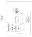
- FIG. 3 is a block diagram showing an arrangement of functions for paper feeding of the image forming apparatus 10 of an exemplary embodiment of the present invention
- FIG. 4 illustrates a concrete example of a remaining amount of paper detector in the image forming apparatus 10 of an exemplary embodiment of the present invention
- FIG. 5 illustrates an output signal of a photo sensor 43 .
- FIG. 6 is a flowchart illustrating the operation of the image forming apparatus 10 of an exemplary embodiment of the present invention.
- Some types of image forming apparatus such as copiers and printers adapted for producing large-size prints such as drawings are provided with a paper feed device for feeding continuous paper like roll paper and is configured to form an image on roll paper fed by the paper feed device.
- the paper feed device is provided with a cutter that cuts roll paper to a certain length and an image is formed on the thus cut paper.
- the image forming apparatus of this type in order to avoid an adverse effect when paper is cut, the following method is used: slacken paper (forming a loop of paper) on a transport path, stop the driving of the paper feed device when cutting paper, and cut paper during time taken to tighten the slack (make the loop disappear). In this way, a loop is used as a buffer for cutting paper.
- FIG. 1 is a cross sectional diagram depicting a configuration of an image forming apparatus 10 of an exemplary embodiment of the present invention.
- the image forming apparatus 10 includes an image forming unit (image output part) 63 , which is composed of a fixing device 11 , a photoreceptor drum 12 , a development device 13 , a loop forming part 14 , and other components, and roll paper feed devices (continuous paper feed devices) 61 , 62 that feed roll paper (continuous paper) to the image forming unit 63 .
- Each of the roll paper feed device 61 , 62 includes a cutter (cutting unit) 15 , a feed roller 16 , and a roll paper 17 .
- two vertically disposed roll paper feed devices 61 , 62 which can accommodate two roll papers are installed. Because the roll paper feed devices 61 , 62 have the same structure, only the roll paper feed device 61 will be discussed in the following description.
- the feed roller 16 is positioned upstream of transport rollers 22 and functions as a paper feeding part that feeds the roll paper 17 to the image forming unit 63 .
- the loop forming part 14 forms a loop (slack) of the roll paper 17 on a paper transport path (from the transport rollers 22 up to upper transport rollers 21 ) through which the roll paper 17 is fed by the feed roll 16 to the image forming unit 63 .
- the photoreceptor drum 12 is irradiated with light from an exposure device and an electrostatic latent image is formed thereon.
- the electrostatic latent image formed on the photoreceptor drum 12 is developed by the development device 13 and a toner image on the photoreceptor drum 12 developed by the development device 13 is transferred onto the roll paper being transported.
- the toner image transferred onto the roll paper is fixated to the roll paper by the fixing device 11 .
- FIG. 2 a hardware structure of the image forming apparatus 10 in the image forming system of the present exemplary embodiment is shown in FIG. 2 .
- the image forming apparatus 10 includes a CPU 31 , a memory 32 , a storage device 33 such as a hard disk drive (HDD), a communication interface (IF) 34 for transmitting and receiving data to/from an external device via a network, user interface (UI) equipment 35 including a touch panel or a liquid crystal display and a keyboard, and a print engine 36 . These components are interconnected via a control bus 37 .
- a control bus 37 .
- the CPU 31 performs predetermined processing based on a control program stored in the memory 32 or storage device 33 and controls the operation of the image forming apparatus 10 .
- the CPU 31 reads the control program from the memory 32 or storage device 33 and executes the program.
- the program may be stored in a storage medium such as CD-ROM and provided to the CPU 31 .
- FIG. 3 is a block diagram showing an arrangement of functions for paper feeding of the image forming apparatus 10 , wherein these functions are implemented by executing the above control program.
- the image forming apparatus 10 of the present exemplary embodiment includes a paper remaining amount detecting part 51 , a controller 52 , a cutter 15 , a motor 53 for rotating the feed roller 16 , a motor driver 54 for control of rotation of the motor 53 and transport rollers 21 , 22 .
- the paper remaining amount detecting part 51 has a function that detects the remaining amount of the roll paper 17 and conveys it to the controller 52 .
- the controller 52 controls the operations of the feed roller 16 , cutter 15 , transport rollers 21 , 22 , etc. based on the remaining amount of the roll paper 17 detected by the paper remaining amount detecting part 51 . That is, the controller 52 functions as a transport controller that controls transport of the roll paper 17 and a cutting controller that controls the cutter 15 to cut the roll paper 17 .
- the controller 52 controls the operation to reduce the loop length (slack length) of a loop formed by the loop forming part 14 and apply tension to the roll paper 17 .
- the controller 52 controls the loop forming part 14 to increase the loop to be formed so that the loop is formed when the roll paper 17 is cut.
- the paper length more than the predefined value is the paper length for which it is required to reduce the initially formed loop and apply tension to the roll paper 17 .
- the controller 52 does not perform the control for reducing the loop length even if the paper length specified for the accepted print job is more than A0 size that is the predefined value which has been set beforehand.
- the controller 52 reduces the length of a loop formed by the loop forming part 14 .
- the controller 52 controls the loop forming part 14 to increase the loop to be formed by the loop forming part 14 .
- the controller 52 controls the loop forming part 14 so that the roll paper 17 with a loop formed thereon by the loop forming part 14 is transported.
- the controller 52 controls the loop forming part 14 so that the roll paper 17 with a loop formed thereon by the loop forming part 14 is transported.
- the controller 52 controls the cutter 15 to cut the continuous paper during a time taken to stretch the loop formed by the loop forming part 14 , when the roll paper 17 has run out.
- the present invention is not limited to such a case.
- the present invention is equally applicable to a case where, for example, a copy instruction or the like is accepted and an image is formed on continuous paper according to the accepted copy instruction or the like.
- this detection may be performed when a print job or copy instruction has been accepted, when paper reading has been completed, or before an initially produced loop is reduced.
- the cutter 15 is a cutting unit that cuts the roll paper 17 during a time taken to stretch the loop formed by the loop forming part 14 .
- the controller 52 controls the cutter 15 to cut continuous paper 17 when the length of the roll paper 17 fed to the image forming unit 63 has reached the paper length specified by a print job or at the time of roll end, when the roll paper 17 has run out.
- the image forming apparatus 10 is configured to include a function of counting a paper length to feed. For this purpose, it suffices to obtain information about rotation of the feed roller 16 .
- the apparatus is configured such that a pulse signal for control of the motor 53 for driving the feed roller 16 is fed back from the motor driver 54 to the controller 52 .
- the paper remaining amount detecting part 51 is constructed with a disk 42 and a photo sensor 43 .
- the feed roller 16 is driven by the motor 53 shown in FIG. 3 and reels out the roll paper 17 in the arrow direction.
- the roll paper 17 and the paper shaft (core) 41 rotate and, by a suitable mechanism, this rotation is conveyed to the disk 42 via a gear.
- the disk 42 has a large number of slits which are radially arranged.
- the photo sensor 43 is located to interpose the disk 42 between its parts.
- the photo sensor 43 is configured such that light emitted from a light emitting part and passing through a slit is detected by a light receiving part.
- the output signal of the photo sensor 43 is a pulse signal.
- One cycle of the output signal changes depending on the speed of rotation of the paper shaft 41 .
- the number of rotations of the paper shaft 41 for a given period of time that is, on/off periods (cycles) detected by the photo sensor 43 change, as the outside diameter of the roll paper 17 changes.
- the number of pulses detected for a given period of time changes.
- pulse signal output is no longer provided after time t 1 , when no pulse will be detected for a given period of time. This indicates that the rotation of the roll paper 17 is stopped, that is, it can be determined that it is the time of roll paper end.
- FIG. 6 is a flowchart illustrating the operation of the image forming apparatus 10 of the present exemplary embodiment.
- step S 101 When the image forming apparatus 10 accepts a print job, and when the roll paper 17 is reeled out by the feed roller 16 and paper feeding to the image forming unit 63 starts, counting a paper length fed to the image forming unit 63 is started (step S 101 ).
- the roll paper 17 fed by the feed roller 16 passes the cutter 15 and is temporarily stopped at the transport rollers 21 , and a loop is formed (step S 102 ).
- the rotation of the transport rollers 21 is restarted and the roll paper 17 is transported to the image forming unit 63 .
- step S 103 it is determined whether the paper length specified by the print job is more than a predefined value, e.g., A0 size which has been set beforehand (step S 103 ). If the paper length specified by the print job is shorter than the predefined value which has been set beforehand, as determined at step S 103 , control for reducing the loop is not performed and paper length counting is continued until the fed paper length has reached the paper length specified by the print job (step S 108 ).
- step S 109 only the driving of the roll paper feed device 61 is stopped and the paper is cut by the cutter 15 during a time taken to stretch the loop formed in the loop forming part 14 (step S 109 ). That is, the paper is cut by the cutter 15 , while the image forming operation is continued.
- L T ⁇ V (1)
- step S 104 if the paper length specified by the print job is more than the predefined value which has been set beforehand, a comparison is made between the remaining amount of paper detected by the paper remaining amount detecting part 51 and the remaining (blank) paper length to be used for the print job (step S 104 ).
- step S 104 if the remaining amount of paper detected by the paper remaining amount detecting part 51 is longer than the paper length to be used for the print job, that is, an image formation specified by the print job can be completed without paper run-out, control is performed to reduce the length of the loop formed to stabilize paper feed performance and to increase the tension on the paper (step S 105 ).
- a specific value to determine whether paper length is exceptionally long is set and, when the result of paper length counting has reached the specific value, the feed roller 16 is stopped.
- the driving of the roll paper feed device 61 is temporarily stopped to reduce the loop. If the loop is completely stretched, an impact on the paper gives rise to an adverse effect on an image produced on the paper. Hence, with a slight slack remaining, the driving of the roll paper feed device 61 is restarted. At this time, the paper feed speed of the roll paper feed device 61 is set slightly slower than the paper speed in the image forming unit 63 . Thereby, it is possible to increase the tension on the paper without having an adverse effect on an image produced on the paper.
- a loop having the loop length L is formed again by increasing the paper feed speed of the roll paper feed device 61 (step S 107 ).
- the driving of the roll paper feed device 61 is stopped and the paper is cut by the cutter (step S 109 ).
- step S 104 if the remaining amount of paper detected by the paper remaining amount detecting part 51 is shorter than the paper length to be used for the print job, that is, the paper will run out before completion of the image formation specified by the print job, control for reducing the loop is not performed and paper feeding is continued toward the specified paper length (step S 108 ). However, in this case, the specified paper length is not reached, because the roll paper runs out during the image formation.
- the paper Upon detecting the roll paper end, the paper is cut by the cutter 15 and ejected outside of the apparatus. In this case, since the control for reducing the loop is not performed, paper with a loop formed thereon is cut even if the roll paper end occurs during image output.
- control scheme is illustrated in which the controller 52 does not perform the control for reducing the loop length, if the blank paper length to be used for the accepted print job is longer than the remaining amount of the roll paper 17 detected by the paper remaining amount detecting part 51 , as in step S 104 , even if the paper length specified for the accepted print job is more than A0 size that is the predefined value which has been set beforehand.
- the present invention is not limited to this scheme.
- the control scheme may be modified such that the controller 52 does not perform the control for reducing the loop length, if the remaining amount of the roll paper 17 detected by the paper remaining amount detecting part 51 has become less than a threshold value which has been set beforehand, even if the paper length specified for the accepted print job is more than A0 size that is the predefined value which has been set beforehand.
- This variation of the control scheme can be implemented by using a threshold value which has been set instead of the paper length to be used for the accepted print job in the above-described exemplary embodiment.
Landscapes
- Handling Of Sheets (AREA)
- Paper Feeding For Electrophotography (AREA)
- Controlling Sheets Or Webs (AREA)
- Controlling Rewinding, Feeding, Winding, Or Abnormalities Of Webs (AREA)
Abstract
Description
L=T×V (1)
Claims (13)
Applications Claiming Priority (2)
| Application Number | Priority Date | Filing Date | Title |
|---|---|---|---|
| JP2008-075074 | 2008-03-24 | ||
| JP2008075074A JP4529189B2 (en) | 2008-03-24 | 2008-03-24 | Continuous paper feeder, image forming apparatus, and program |
Publications (2)
| Publication Number | Publication Date |
|---|---|
| US20090236385A1 US20090236385A1 (en) | 2009-09-24 |
| US8090308B2 true US8090308B2 (en) | 2012-01-03 |
Family
ID=41087878
Family Applications (1)
| Application Number | Title | Priority Date | Filing Date |
|---|---|---|---|
| US12/245,965 Expired - Fee Related US8090308B2 (en) | 2008-03-24 | 2008-10-06 | Continuous paper feed device, image forming apparatus, continuous paper feeding method and computer readable media storing program |
Country Status (2)
| Country | Link |
|---|---|
| US (1) | US8090308B2 (en) |
| JP (1) | JP4529189B2 (en) |
Cited By (2)
| Publication number | Priority date | Publication date | Assignee | Title |
|---|---|---|---|---|
| US20140119804A1 (en) * | 2012-10-31 | 2014-05-01 | Takashi Hatano | Recording medium conveyance apparatus, image forming apparatus, recording medium conveyance method and recording medium storing program of recording medium conveyance method |
| US11173731B2 (en) * | 2017-12-08 | 2021-11-16 | Toshiba Tec Kabushiki Kaisha | Printer and method |
Families Citing this family (7)
| Publication number | Priority date | Publication date | Assignee | Title |
|---|---|---|---|---|
| EP2408623A4 (en) * | 2009-03-19 | 2018-01-10 | Hewlett-Packard Development Company, L.P. | Media roll management |
| JP5822333B2 (en) * | 2010-06-21 | 2015-11-24 | 株式会社セイコーアイ・インフォテック | Image forming apparatus |
| JP5672122B2 (en) * | 2011-04-08 | 2015-02-18 | 株式会社リコー | Image forming apparatus and program |
| JP5804826B2 (en) * | 2011-07-29 | 2015-11-04 | キヤノン株式会社 | Image forming apparatus |
| JP5917084B2 (en) | 2011-10-21 | 2016-05-11 | キヤノン株式会社 | Recording apparatus, control method, and program |
| JP6187440B2 (en) * | 2014-12-09 | 2017-08-30 | コニカミノルタ株式会社 | Image forming apparatus |
| CN115407627B (en) * | 2022-10-11 | 2025-08-29 | 珠海奔图电子有限公司 | Paper quantity detection method, paper supply control method, device and storage medium |
Citations (8)
| Publication number | Priority date | Publication date | Assignee | Title |
|---|---|---|---|---|
| JPH01231745A (en) | 1988-03-08 | 1989-09-18 | Matsushita Graphic Commun Syst Inc | Recorder |
| JPH06278938A (en) | 1993-03-26 | 1994-10-04 | Ootonikusu:Kk | Roll paper feeding device |
| JPH0891651A (en) | 1994-09-20 | 1996-04-09 | Fuji Xerox Co Ltd | Rolled paper supplying device |
| JPH09249341A (en) | 1996-01-12 | 1997-09-22 | Ricoh Co Ltd | Image forming device |
| US6091928A (en) * | 1997-01-13 | 2000-07-18 | Copyer Co., Ltd. | Rolled paper supply device for image forming apparatuses |
| JP2002284439A (en) | 2001-03-26 | 2002-10-03 | Seiko Instruments Inc | Residual paper quantity control device, and printing device |
| US20030035671A1 (en) * | 2000-02-03 | 2003-02-20 | Estabrooks David Allen | On demand media web electrophotographic printing apparatus |
| JP2004136514A (en) | 2002-10-16 | 2004-05-13 | Ricoh Co Ltd | Roll paper feeder |
-
2008
- 2008-03-24 JP JP2008075074A patent/JP4529189B2/en not_active Expired - Fee Related
- 2008-10-06 US US12/245,965 patent/US8090308B2/en not_active Expired - Fee Related
Patent Citations (8)
| Publication number | Priority date | Publication date | Assignee | Title |
|---|---|---|---|---|
| JPH01231745A (en) | 1988-03-08 | 1989-09-18 | Matsushita Graphic Commun Syst Inc | Recorder |
| JPH06278938A (en) | 1993-03-26 | 1994-10-04 | Ootonikusu:Kk | Roll paper feeding device |
| JPH0891651A (en) | 1994-09-20 | 1996-04-09 | Fuji Xerox Co Ltd | Rolled paper supplying device |
| JPH09249341A (en) | 1996-01-12 | 1997-09-22 | Ricoh Co Ltd | Image forming device |
| US6091928A (en) * | 1997-01-13 | 2000-07-18 | Copyer Co., Ltd. | Rolled paper supply device for image forming apparatuses |
| US20030035671A1 (en) * | 2000-02-03 | 2003-02-20 | Estabrooks David Allen | On demand media web electrophotographic printing apparatus |
| JP2002284439A (en) | 2001-03-26 | 2002-10-03 | Seiko Instruments Inc | Residual paper quantity control device, and printing device |
| JP2004136514A (en) | 2002-10-16 | 2004-05-13 | Ricoh Co Ltd | Roll paper feeder |
Non-Patent Citations (1)
| Title |
|---|
| Mar. 5, 2010 Office Action issued in Japanese Patent Application No. 2008-075074 (with translation). |
Cited By (3)
| Publication number | Priority date | Publication date | Assignee | Title |
|---|---|---|---|---|
| US20140119804A1 (en) * | 2012-10-31 | 2014-05-01 | Takashi Hatano | Recording medium conveyance apparatus, image forming apparatus, recording medium conveyance method and recording medium storing program of recording medium conveyance method |
| US9248987B2 (en) * | 2012-10-31 | 2016-02-02 | Ricoh Company, Ltd. | Recording medium conveyance apparatus, image forming apparatus, recording medium conveyance method and recording medium storing program of recording medium conveyance method |
| US11173731B2 (en) * | 2017-12-08 | 2021-11-16 | Toshiba Tec Kabushiki Kaisha | Printer and method |
Also Published As
| Publication number | Publication date |
|---|---|
| US20090236385A1 (en) | 2009-09-24 |
| JP2009227408A (en) | 2009-10-08 |
| JP4529189B2 (en) | 2010-08-25 |
Similar Documents
| Publication | Publication Date | Title |
|---|---|---|
| US8090308B2 (en) | Continuous paper feed device, image forming apparatus, continuous paper feeding method and computer readable media storing program | |
| US6786483B2 (en) | Sheet processing apparatus and image forming system having the same | |
| JP7226022B2 (en) | printer | |
| JP2004331357A (en) | Paper transport device and image forming apparatus including the paper transport device | |
| US20150338810A1 (en) | Image forming device, image forming system, image-formation commanding device, and image forming method | |
| JP5007824B2 (en) | Continuous paper feeder, image forming apparatus, and program | |
| US8152164B2 (en) | Image forming apparatus | |
| US9181053B2 (en) | Paper-feeding device and image forming apparatus | |
| US10444687B2 (en) | Image forming apparatus | |
| JP2018072436A (en) | Image forming apparatus | |
| US10520873B2 (en) | Image forming apparatus and image forming method | |
| US7325989B2 (en) | Paper supply apparatus and image formation device | |
| JP2004315177A (en) | Paper transport device and image forming device | |
| JP2006248733A (en) | Image forming device | |
| JP2004136514A (en) | Roll paper feeder | |
| JP2018108644A (en) | Image formation apparatus and image formation method | |
| JP4814066B2 (en) | Sheet-like medium conveying apparatus, image forming apparatus, and sheet-like medium conveying method | |
| US9248987B2 (en) | Recording medium conveyance apparatus, image forming apparatus, recording medium conveyance method and recording medium storing program of recording medium conveyance method | |
| JP5648471B2 (en) | Image forming apparatus | |
| JP2013245065A (en) | Sheet ejection device and image forming apparatus | |
| JP7346074B2 (en) | Image forming device | |
| JP6929512B2 (en) | Transfer device and image forming device | |
| JP6720025B2 (en) | Image forming device | |
| JPH0748050A (en) | Image forming device | |
| JP2019029951A (en) | Image formation device, control method and program |
Legal Events
| Date | Code | Title | Description |
|---|---|---|---|
| AS | Assignment |
Owner name: FUJI XEROX CO., LTD., JAPAN Free format text: ASSIGNMENT OF ASSIGNORS INTEREST;ASSIGNOR:ITOH, KEIJI;REEL/FRAME:021643/0256 Effective date: 20081001 |
|
| ZAAA | Notice of allowance and fees due |
Free format text: ORIGINAL CODE: NOA |
|
| ZAAB | Notice of allowance mailed |
Free format text: ORIGINAL CODE: MN/=. |
|
| FEPP | Fee payment procedure |
Free format text: PAYOR NUMBER ASSIGNED (ORIGINAL EVENT CODE: ASPN); ENTITY STATUS OF PATENT OWNER: LARGE ENTITY |
|
| STCF | Information on status: patent grant |
Free format text: PATENTED CASE |
|
| FPAY | Fee payment |
Year of fee payment: 4 |
|
| MAFP | Maintenance fee payment |
Free format text: PAYMENT OF MAINTENANCE FEE, 8TH YEAR, LARGE ENTITY (ORIGINAL EVENT CODE: M1552); ENTITY STATUS OF PATENT OWNER: LARGE ENTITY Year of fee payment: 8 |
|
| AS | Assignment |
Owner name: FUJIFILM BUSINESS INNOVATION CORP., JAPAN Free format text: CHANGE OF NAME;ASSIGNOR:FUJI XEROX CO., LTD.;REEL/FRAME:058287/0056 Effective date: 20210401 |
|
| FEPP | Fee payment procedure |
Free format text: MAINTENANCE FEE REMINDER MAILED (ORIGINAL EVENT CODE: REM.); ENTITY STATUS OF PATENT OWNER: LARGE ENTITY |
|
| LAPS | Lapse for failure to pay maintenance fees |
Free format text: PATENT EXPIRED FOR FAILURE TO PAY MAINTENANCE FEES (ORIGINAL EVENT CODE: EXP.); ENTITY STATUS OF PATENT OWNER: LARGE ENTITY |
|
| STCH | Information on status: patent discontinuation |
Free format text: PATENT EXPIRED DUE TO NONPAYMENT OF MAINTENANCE FEES UNDER 37 CFR 1.362 |
|
| FP | Lapsed due to failure to pay maintenance fee |
Effective date: 20240103 |