US80903A - Improvement in sawing-machines - Google Patents
Improvement in sawing-machines Download PDFInfo
- Publication number
- US80903A US80903A US80903DA US80903A US 80903 A US80903 A US 80903A US 80903D A US80903D A US 80903DA US 80903 A US80903 A US 80903A
- Authority
- US
- United States
- Prior art keywords
- shaft
- wheel
- sawing
- machines
- improvement
- Prior art date
- Legal status (The legal status is an assumption and is not a legal conclusion. Google has not performed a legal analysis and makes no representation as to the accuracy of the status listed.)
- Expired - Lifetime
Links
- 230000036633 rest Effects 0.000 description 8
- 230000000284 resting Effects 0.000 description 4
- 239000002965 rope Substances 0.000 description 4
- 230000001154 acute Effects 0.000 description 2
- 238000010276 construction Methods 0.000 description 2
- 230000000875 corresponding Effects 0.000 description 2
- 230000002452 interceptive Effects 0.000 description 2
- 230000000414 obstructive Effects 0.000 description 2
- 230000000630 rising Effects 0.000 description 2
Images
Classifications
-
- B—PERFORMING OPERATIONS; TRANSPORTING
- B26—HAND CUTTING TOOLS; CUTTING; SEVERING
- B26D—CUTTING; DETAILS COMMON TO MACHINES FOR PERFORATING, PUNCHING, CUTTING-OUT, STAMPING-OUT OR SEVERING
- B26D7/00—Details of apparatus for cutting, cutting-out, stamping-out, punching, perforating, or severing by means other than cutting
- B26D7/01—Means for holding or positioning work
- B26D7/015—Means for holding or positioning work for sheet material or piles of sheets
- B26D7/016—Back gauges
-
- Y—GENERAL TAGGING OF NEW TECHNOLOGICAL DEVELOPMENTS; GENERAL TAGGING OF CROSS-SECTIONAL TECHNOLOGIES SPANNING OVER SEVERAL SECTIONS OF THE IPC; TECHNICAL SUBJECTS COVERED BY FORMER USPC CROSS-REFERENCE ART COLLECTIONS [XRACs] AND DIGESTS
- Y10—TECHNICAL SUBJECTS COVERED BY FORMER USPC
- Y10T—TECHNICAL SUBJECTS COVERED BY FORMER US CLASSIFICATION
- Y10T83/00—Cutting
- Y10T83/647—With means to convey work relative to tool station
- Y10T83/6569—With means to stop work conveyor
-
- Y—GENERAL TAGGING OF NEW TECHNOLOGICAL DEVELOPMENTS; GENERAL TAGGING OF CROSS-SECTIONAL TECHNOLOGIES SPANNING OVER SEVERAL SECTIONS OF THE IPC; TECHNICAL SUBJECTS COVERED BY FORMER USPC CROSS-REFERENCE ART COLLECTIONS [XRACs] AND DIGESTS
- Y10—TECHNICAL SUBJECTS COVERED BY FORMER USPC
- Y10T—TECHNICAL SUBJECTS COVERED BY FORMER US CLASSIFICATION
- Y10T83/00—Cutting
- Y10T83/647—With means to convey work relative to tool station
- Y10T83/6668—Interrelated work-feeding means and tool-moving means
Definitions
- This invention relates to certain improvements in sawing-machines; and it consists in a novel arrangement for adjusting the log forward or backward at will, as will be fully described hereinafter.
- Figure l represents a plan view of my sawing-machine; Fig. 2, a side elevation, and Figs. 3 and 4 views of parts detached.
- a AA2 represent the bedpieces, which may be constructed in any proper manner. In this case they consist of two parallel beams, A A', and the beam A2, which latter forms an acute angle with the former, the whole being joined by the crosspieces a a.
- ' B represents the main shaft, by means of which power is communicated to the machine, which shaft rests in suitable bearings in the beams A A2.
- C C represent standards which rise from beams A A2 and form bearings for shaft D, upon which latter is placed the pitman-wheel d, as shown.
- vd. represents a pinion which is operated by geanwheel b of shaft B.
- b represents a sleeve-clutch upon shaft B, which revolves with the shaft, being secured thereto by means of a-spline or other similar arrangement, but which has consequently free movement to either side.
- This sliding sleeve is constructedwith a groove in its center, in which rests the free end of the spring E, the iixed end of which latter is secured in the cross-piece c3.
- F represents a lever pivoted to the crossbar f, the short arm of which extends down ward and rests upon spring E, the end being notched, as shown, for the purpose of grasping it.
- the long arm extends upward to a convenient point to be reached by the operator.
- b2 b2 represent bevel gear-wheels, which are loose upon shaft B, and which are provided with projections upon the inner sides corresponding with the depression in the clutchsleeve b.
- G represents a shaft resting in bearings in crosspieces cc, to one end of which isattached the bevel gear-wheel g, and to the other the pinion g'.
- H represents a shaft resting in bearings in cross-pieces a a', to one end of which is attached the gear-wheel h, operated by pinion g', and to the other the roller h', as shown.
- This roller may be constructed of any desired form and arranged in any suitable manner.
- I represents the pitnian, which is attached in the usual manner to the pitman-wheel d.
- J J represent ways which are pivoted upon each side just forward of the center of the pitman Wheel, which ways are slotted, as shown, to form bearings for the slidet' of the pitman.
- J J represent curved stays, which rigidly connect the ways together without interfering in any way with the free movement of the pitman.
- K represents a standard rising from beams A A,in which is hung the shaft It with ratchetwheel la and crank k2, as shown.
- K represents a'strap, rope, or chain, one end of which is attached to one of the stays J and the other to the shaft k.
- the log is adjusted forward or backward, as may be desired, by moving the lever F in the proper direction, for by moving the lever to eitherside the sleeve-clutch b is forced into contact with one of the gear-wheels b2, which is by this means rigidly connected for the time hobos to the main B, and is forced to revolve with it.
- the wheels b2 engage with the gear-wheel g, motion is thus communicated to the latterin ⁇ one direction or the other, the direction depending upon the wheel communicating the motion.
- the shaft G by its pinion g', engages with gear-wheelh of shaft H,
Description
UNITED STATES l PATENT OrEIcEo JAMES BRIGGS, OF LYONS, OHIO.'`
Specication forming part of Letters Patent No. 80,903. dated August 11, 1868.
To all whom, it may concern: A
Be it known that I, JAMES BRIGGs, -of
Lyons, in the county of Fulton and State of l description of the same, reference being had to the accompanying drawings, and tothe letters of reference marked thereon.
This invention relates to certain improvements in sawing-machines; and it consists in a novel arrangement for adjusting the log forward or backward at will, as will be fully described hereinafter.
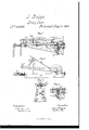
Figure l represents a plan view of my sawing-machine; Fig. 2, a side elevation, and Figs. 3 and 4 views of parts detached.
In the drawings, A AA2 represent the bedpieces, which may be constructed in any proper manner. In this case they consist of two parallel beams, A A', and the beam A2, which latter forms an acute angle with the former, the whole being joined by the crosspieces a a.
' B represents the main shaft, by means of which power is communicated to the machine, which shaft rests in suitable bearings in the beams A A2.
C C represent standards which rise from beams A A2 and form bearings for shaft D, upon which latter is placed the pitman-wheel d, as shown.
vd. represents a pinion which is operated by geanwheel b of shaft B.
b represents a sleeve-clutch upon shaft B, which revolves with the shaft, being secured thereto by means of a-spline or other similar arrangement, but which has consequently free movement to either side. This sliding sleeve is constructedwith a groove in its center, in which rests the free end of the spring E, the iixed end of which latter is secured in the cross-piece c3.
F represents a lever pivoted to the crossbar f, the short arm of which extends down ward and rests upon spring E, the end being notched, as shown, for the purpose of grasping it. The long arm extends upward to a convenient point to be reached by the operator.
b2 b2 represent bevel gear-wheels, which are loose upon shaft B, and which are provided with projections upon the inner sides corresponding with the depression in the clutchsleeve b. j
G represents a shaft resting in bearings in crosspieces cc, to one end of which isattached the bevel gear-wheel g, and to the other the pinion g'.
H represents a shaft resting in bearings in cross-pieces a a', to one end of which is attached the gear-wheel h, operated by pinion g', and to the other the roller h', as shown. This roller may be constructed of any desired form and arranged in any suitable manner.
I represents the pitnian, which is attached in the usual manner to the pitman-wheel d.
J J represent ways which are pivoted upon each side just forward of the center of the pitman Wheel, which ways are slotted, as shown, to form bearings for the slidet' of the pitman.
J J represent curved stays, which rigidly connect the ways together without interfering in any way with the free movement of the pitman.
K represents a standard rising from beams A A,in which is hung the shaft It with ratchetwheel la and crank k2, as shown. f
K represents a'strap, rope, or chain, one end of which is attached to one of the stays J and the other to the shaft k.
From this description the nature and operation of my invention will be readily` understood.
The machine having been put in motion, the log is adjusted forward or backward, as may be desired, by moving the lever F in the proper direction, for by moving the lever to eitherside the sleeve-clutch b is forced into contact with one of the gear-wheels b2, which is by this means rigidly connected for the time heilig to the main B, and is forced to revolve with it. As the wheels b2 engage with the gear-wheel g, motion is thus communicated to the latterin `one direction or the other, the direction depending upon the wheel communicating the motion. The shaft G, by its pinion g', engages with gear-wheelh of shaft H,
which latter operates the roller upon which the log rests. The sawis adj usted up or down,
so as to rest properly upon the log, by turning the crank k2 of shaft k, by which means the rope or chain is wound up or unwound, and the Ways consequently elevated or de pressed. The ratchet-wheel and pawl k2 sustain the ways in any desired position.
By the'construction and arrangement herein described a valuable and efficient sawingmachine is produced. The log is easily handled and the saw readily adjusted in such manner as to be always at right angles to the 10g,whereas when arranged in the usual manner the saw is often placed upon the log at an incline, in which case the power is very disadvantageousl y applied. The elevated bearings of the pitman-wheel also place it and the pitmau up out of the way clear from obstructions.
JAM ES BRIGGS.
Witnesses:
CHARLES RYND, ALBERT N. DREW.
Publications (1)
| Publication Number | Publication Date |
|---|---|
| US80903A true US80903A (en) | 1868-08-11 |
Family
ID=2150398
Family Applications (1)
| Application Number | Title | Priority Date | Filing Date |
|---|---|---|---|
| US80903D Expired - Lifetime US80903A (en) | Improvement in sawing-machines |
Country Status (1)
| Country | Link |
|---|---|
| US (1) | US80903A (en) |
-
0
- US US80903D patent/US80903A/en not_active Expired - Lifetime
Similar Documents
| Publication | Publication Date | Title |
|---|---|---|
| US80903A (en) | Improvement in sawing-machines | |
| US229908A (en) | Edwaed nunatf | |
| US103709A (en) | Improvement in sawing-machines | |
| US97958A (en) | Improvement in sa wing-machine | |
| US139578A (en) | Improvement in machines for moving logs | |
| US77223A (en) | Improved car-brake and starter | |
| US81418A (en) | Pius lee shepler | |
| US91461A (en) | Improvement in sawinq-machine | |
| US18446A (en) | Improvement in steam-plows | |
| US75441A (en) | maxey | |
| US65517A (en) | sweetl-and | |
| US81356A (en) | Improvement in sawing-machines | |
| US82047A (en) | Improvement in saw-filing machine | |
| US104079A (en) | Improvement in sawing-machine | |
| US240450A (en) | Halp to geobge m | |
| US177619A (en) | Improvement in drag-sawing machines | |
| USRE8289E (en) | Improvement in head-blocks for saw-mills | |
| US53804A (en) | edmonds | |
| US20800A (en) | Improvement sn rotating shafts without using a crank | |
| US122117A (en) | Improvement in shingle-machines | |
| US91589A (en) | Samuel anderson | |
| US92124A (en) | Improvement in sawing-machines | |
| US91121A (en) | Improvement in sawing-machines | |
| US91544A (en) | Improvement in wood-sawing- machines | |
| US82789A (en) | District |