US809010A - Leather-working machine. - Google Patents
Leather-working machine. Download PDFInfo
- Publication number
- US809010A US809010A US19277704A US1904192777A US809010A US 809010 A US809010 A US 809010A US 19277704 A US19277704 A US 19277704A US 1904192777 A US1904192777 A US 1904192777A US 809010 A US809010 A US 809010A
- Authority
- US
- United States
- Prior art keywords
- hide
- skin
- carrier
- support
- work
- Prior art date
- Legal status (The legal status is an assumption and is not a legal conclusion. Google has not performed a legal analysis and makes no representation as to the accuracy of the status listed.)
- Expired - Lifetime
Links
- 238000010276 construction Methods 0.000 description 4
- 239000010985 leather Substances 0.000 description 3
- 230000006378 damage Effects 0.000 description 2
- 239000000463 material Substances 0.000 description 2
- 208000027418 Wounds and injury Diseases 0.000 description 1
- 239000000969 carrier Substances 0.000 description 1
- 238000000151 deposition Methods 0.000 description 1
- 230000000994 depressogenic effect Effects 0.000 description 1
- 230000000694 effects Effects 0.000 description 1
- 208000014674 injury Diseases 0.000 description 1
- 239000011435 rock Substances 0.000 description 1
- 239000002023 wood Substances 0.000 description 1
Images
Classifications
-
- C—CHEMISTRY; METALLURGY
- C14—SKINS; HIDES; PELTS; LEATHER
- C14B—MECHANICAL TREATMENT OR PROCESSING OF SKINS, HIDES OR LEATHER IN GENERAL; PELT-SHEARING MACHINES; INTESTINE-SPLITTING MACHINES
- C14B1/00—Manufacture of leather; Machines or devices therefor
- C14B1/02—Fleshing, unhairing, samming, stretching-out, setting-out, shaving, splitting, or skiving skins, hides, or leather
- C14B1/04—Fleshing, unhairing, samming, stretching-out, setting-out, shaving, splitting, or skiving skins, hides, or leather using slicking, scraping, or smoothing-out cylinders or blades fixed on supports, e.g. cylinders, in a plane substantially at right angles to the working surface
- C14B1/12—Fleshing, unhairing, samming, stretching-out, setting-out, shaving, splitting, or skiving skins, hides, or leather using slicking, scraping, or smoothing-out cylinders or blades fixed on supports, e.g. cylinders, in a plane substantially at right angles to the working surface in machines with plane supporting bed-plates
Definitions
- the invention relates to a machine for treating hides, skins, and leather, and is an improvement upon the machine shown and described in patent granted to me December 8, 1903, No. 746,144, to which reference may be had for a more complete statement of the purposes'and uses, as well as of the general construction and operation, of the machine.
- the present invention has for its object an improvement in those parts of the machine of my said Patent No. 746,144, which are more especially concerned in what may be termed the preliminary operation of presenting a portion of the hide or skin to the action of one of the operating tools or rolls in order that one portion of the hide or skin intermediate its ends may be worked or treated prior to the working or treating of the remaining portions of the hide or skin.
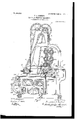
- Figure 1 is a vertical section of a putting-out machine embodying my invention.
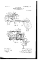
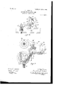
- Fig. 2 is a detail in side elevation of the carrier and its operating mechanism.
- Fig. 3 is a section on line 3 3, Fig. 2, showing in elevation a portion of the carrier, as also a portion of the table, clearing device, and the holder hereinafter referred to.
- Fig. 4 is a detail showing, partly in side elevation and partly in section, the holder hereinafter described.
- Fig. 5 is adetail designed to show more clearly theoperation of the clearer, as also of the pivoted portion or leaf of the table.
- My invention is shown as embodied in an upright serial table -,machine having three work-supports or tables a, which are pivotally secured to an endless carrier 7), passing around suitable sprocket-wheels c d e, mountconstruction suitable for the particular work to be performed by the machine.
- the working tools consist of two rolls or cylinders m n on one side of the path of movement of the table and three rolls or cylinders o p q on the opposite side of the path of movement of the table.
- My present invention like that of my invention set forth in the patent hereinabove referred to, has for its primary object to effeet a proper working of the entire surface of the hide or skin by the operating rolls or tools of the machine.
- My present invention more particularly relates to the various means employed for subjecting the hide or skin to this preliminary operation and for then properly ilocating it on the upward-moving table or support, uponwhich the treatment of the hide is continued or completed. These means will now be described.
- a work-support is shown at 1, said sup- 7 port being secured in any suitable manner to the side frames j.
- the said Work-support eXtendsfrom the front of themachine (shown at the right, Fig. 1) rearwardly and horizontally to apoint near to the vertical plane of movement of the tables a. At the rearward of this horizontal portion a trough is formed,
- the front side or wall of the said trough which adjoins the rear end of the horizontal portion 1 of the work-support, is formed by a pivoted or hinged piece 4. (See Fig. 1,)
- the said piece 4 is hinged or pivoted to the bottom portion 2 of the trough at 60, and the upper edge of the said piece 4 rests against the rear edge of the horizontal portion 1 of the worksupport.
- This trough-shaped portion of the I work-support serves as a receptacle for one side or portion of the hide or skin while the said hide or skin is undergoing the preliminary operation.
- the side4 of the said trough or receptacle is hinged, so that it may swing rearwardly to permit the upward movement of the tables a.
- its upper edge also serves to hold the hide or skin .back and clear of the table, and thus is of value in effecting proper contact of the upper edge of the table with that portion of the hide or skin which has received the preliminary treatment.
- the preliminary operationI provide a horizontally-moving carrier, which is mounted upon sliding supports 5, there being one of such supports at each end of the machine.
- the supports or side pieces 5 slide upon suitable ways or tracks6, secured to the side frames of the machine and extending horizontally from the front to the rear thereof.
- the forward ends of the supports 5 are provided with an upward projection 7, at the top of which is journaled a rock-shaft 8. (See Fig. 3.)
- a sleeve or boss 9 having an upwardly-extending curved arm 10, the upper end of which is shaped as shown at 11, Figs. 2 and 3.
- the inner or rearward face of the bar or beam. 12 is curved or concaved, as shown at 13, Fig. 2, to correspond substantially with the periphery of the operating-roll 0 and is covered with a yielding covering of leather or similar material in the same manner as are the sides of the work-supports a to form a yielding support for the skin while it is being operated upon by the roll.
- the shaft 8 is provided with a downwardly and forwardly projecting arm 14, (see Fig.
- the sliding frame-pieces 5, which support the carrier comprising the parts above described, are reciprocated by means of camoperated pivoted levers 22, (see Fig. 2,) one at each end of the machine;
- the levers 22 are pivoted at 23 to a stud on the frame, and the upper ends thereof are provided with pins 24, which-engage slots 25 in the downwardlyprojecting portion 26 of the side piece 5.
- the lower ends of the levers 22 are provided with cam-rolls 27, which cooperate with the cam path 28 in the face of the cam-wheel 29.
- the cams 29 are fast on a shaft 30, journaled in the frame of the machine, the said shaft being driven by means of gears in the usual manner, the precise construction and operation of which it will be unnecessary to describe.
- the side pieces 5 are caused to slide rearwardly to carry the skin which is on the beam 12 of the carrier into contact with the operating-roll 0, maintain it in that position a given length of time, and then slide forwardly, holding the skin in position to be taken upwardly upon one of the tables a and also to receive another skin after the one which has just been treated has been carried upward out of the way on the said table a.
- the forward position of the carrier is shown by dotted lines in Fig. 2. is in this position, the operator throws the hide or skin over the beam 12, preferably placing it so that the central section substan tially of the hide will be on the curved face of the beam.
- the work-support 1 is provided with parallel strips 31, (see Figs. 1, 3, and 5,) which extend from front to rear of the work-support and are secured on top thereof.
- a series of clearers or fingers 32 one for each of the spaces 33, which are left between the strips 31, is provided, the lower end of each finger projecting into a corresponding space, as will be clear from Figs. 3 and 5.
- the fingers 32 occupy a substantially vertical position, as shown by dotted lines, Fig. 5, and are secured to a bar 34, extending across the machine, and secured at each end in the downwardly-projecting portion 35 of a lever which is pivoted at 36 near the upper end of the carrier-lever 10.
- the lever 35 is provided with an upwardly and rearwardly extending tripping-arm 37 ,which is curved at its free end at 38 for engagement with a wheel 39, mounted on the shaft of the operating-roll 0.
- the fingers 32 carry the skirts and rear portion of the hide, which is behind the carrier, along with them, and just before the carrier has reached the limit of its rearward movement the trippingarms 37 make contact with the periphery of the wheels 39 on the shaft of the roll 0 and impart to the fingers 32 a sudden rearward movement, causing them to assume the position shown in full lines in Fig. 5. This sudden rearward movement or fiick.
- the dwell of the carrier-operating cam 29 is such, as heretofore described, as to insure the hide being held in contact with the operating-roll 0 a sufficient length of time to complete the operation performed thereon by the said roll.
- the carrier then moves forwardly.
- the trippingarm 37 is clear of the roll 39, the fingers 32 drop back to their vertical position ready for the next forward movement.
- the car rier is in its rearward position, holding the hide.
- a holder or checking-blade which is shown more fully in Fig. 4.
- This device comprises a bar 40, which extends from side to side of the machine above the operating-roll 0 and which is secured at each end in a holder comprising an upwardly-projecting arm 41 and a rearwardly-projecting arm 42, shaped as shown, Fig. 4.
- These arms 41 and 42 join and have formed therein a half boss or journal at 43,
- the said blade having a narrow or dull edge, which, when the carrier is in its extreme rearward position and the hide is in contact with the opcrating-roll 0, makes contact with the hide directly above the point at which the blades of the operating-roll touch it, as will be clear from Fig. 1, and checks or holds the hide against the carrier, thereby preventing the hide from slipping or moving on the carrier while it is being subjected to the operation of the roll 0. Since the holding device is yieldingly mounted, as is also the carrier, the blade 51 is not brought into contact with the hide or held in contact with it so forcibly as to cause the hide any injury.
- What I claim is 1.
- a table or support for the hide or skin means to move it, operatingtools located on opposite sides of the path of movement of the said table or support, a carrier for the hide or skin cooperating with one of said tools to efl'ect working of a portion of I said hide or skin prior to the engagement of the hide, or skin with said table or support, and a clamp to engage the hide or skin while on the carrier and prevent its movement under the influence of the tool cooperating with said carrier, substantially as described.
- a substantially flat table or support for a hide or skin means to move it, operating-tools located on opposite sides of the path of movement of said table or support, a second support for the hide or skin movable substantially at right angles to the path of movement of the said table and cooperating with one of said operating-tools to effect working of a portion of the hide or skin while on said second support, and means 00- operating with said second support to secure the hide or skin thereon against movement under the influence of the operating-tool which cooperates with said second support, substantially as described.
- a table or work-support means to move said table in a substantially vertical path, operating-tools located on op posite sides of the path of movement of said table or work-support, a yielding support over which a hide or skin is adapted to be placed, movable toward and from the path of movement of said table, means for treating the hide or skin while on said yielding support, and a clamping-bar cooperating with the upper end of said yielding support, substantially as described.
- a table or worksupport means to move it, a carrier for a hide or skin movable toward the path in which said table is moved to place the hide or skin into position to be removed from said carrier by said table, means to move said carrier, means for treating the hide or skin while on said carrier, means for treating the hide or skin while on said table, and a clamp cooperating with said carrier to resist movement of. the hide or skin while undergoing treatment on said carrier, said clamp being automatically actuated by said carrier to engage the hide or skin thereon, substantially as described.
- a leather-Working machine in combination a movable table or support, means to move the said table, operating-tools for working a hide or skin on said table, a carrier and an operating-tool for working a portion of a hide or skin on said carrier prior to the engagement of the hide or skin with the movable table, and a clearer to engage that portion of the hide or skin rearward of the carrier and position said portion for proper engagement of the hide or skin with the said movable table or support.
- a leather-working machine in combination a movable table or support, means to move said table, operating-tools for working a hide or skin on said table, a horizontally-movable carrier and means for moving it, and an operating-tool for working a portion of a hide or skin on said carrier prior to the engagement of the hide or skin with the movable table, and a clearer to engage that portion of the hide or skin rearward of the carrier and position said portion for proper engagement of the hide or skin with the said movable table or support.
- a leather-working machine in combination a movable table or support for a hide or skin, means to move it, operatingtools located on opposite sides of the path of movement of the said table, and means on opposite sides of the path of movement of said table to, support the free ends of the hide or skin away from the sides of said table, said means comprising a pivoted portion of the work-support on one side of the table, and the carrier on the other side of the table, substantially as described.
- a leather-working machine in combination a movable table and means for moving it, operating-tools cooperating with said table to work a hide or skin thereon, a horizontal work-support, a horizontallymoving carrier, a cooperating tool for working a portion of a hide or skin on said carrier and a moving clearer for clearing the edge of said hide or skin from said work-support as the carrier moves toward the operating-roll which cooperates therewith.
- a leather-working machine in combination a movable table and means for moving it, operating-tools cooperating with said table to work a hide or skin thereon, a horizontal work-support having strips thereon separated by intermediate spaces a hori- Zontally-moving carrier, a cooperating tool for working a portion of a hide or skin on said carrier, and a moving clearer comprising a series of'lingers projecting into the spaces between the strips on said work-support for clearing the edge of said hide or skin from said work-support as the carrier moves toward the operating-roll which cooperates therewith.
- a movable tab e and means for moving it tools cooperating with said table to work a hide or skin thereon, a horizontal work-support having a trough or depression at the rear side thereof, a horizontally-moving carrier, a cooperating tool for working a portion of a hide or skin on said carrier, and a movin clearer for clearing the edge of said hide or s 'n from said support as the carrier moves toward the operating-roll which operates therewith, and means for accelerating the motion of the clearer at the end of its movement to throw the edge of the hide or skin into the trough or depressed portion of the work-support, substantially as described.
- a leather-working machine in combination a movable table, means for moving it, tools cooperating with said table to work a hide or skin thereon, a horizontal work-support, a moving carrier, a cooperating tool for working a portion of a hide or skin on said carrier, and a holder cooperating with said carrier to securelyhold the hide or skin thereon while it is being operated upon by the cooperating tool, substantially as described.
- a movable table means for moving it, tools cooperating with said table to work a hide or skin thereon, a horizontal work-support, a moving carrier, a cooperating tool for working a portion of a hideor skin on said carrier, and a yielding holder cooperating with said carrier to securely hold the hide or skin thereon while it is being operated upon by the cooperating tool, substantially as described.
- a movable table means for moving it, tools cooperating with said table to work a hide or skin thereon, a horizontal work-support, a moving carrier, a cooperating tool for working a portion of a hide or skin on said carrier, a holder cooperating with said carrier to securely hold the hide or skin thereon while it is being operated upon by the cooperating tool, and a moving clearer for clearing the edge of said hide or skin from said work-support as the carrier moves toward the operating-tool which cooperates therewith.
- a leather-working machine in combination a movable table and means for movin it, tools cooperating with said table to wor: a hide or skin thereon, a horizontal Work-support having a depression or trough rearwardly thereof and hinged leaf or portion intermediate the said horizontal portion of the work-support and the said trough and forming an inclined side of the latter, a horizontally-moving carrier, a cooperating tool for working a portion of a hide or skin on said carrier, and means for moving the edge or rear portion of the hide or skin in advance of the carrier and depositing it in the trough of the work-support, substantially as described.
Landscapes
- Engineering & Computer Science (AREA)
- Manufacturing & Machinery (AREA)
- Mechanical Engineering (AREA)
- Chemical & Material Sciences (AREA)
- Organic Chemistry (AREA)
- Treatment Of Fiber Materials (AREA)
Description
No. 809,010. PATENTED JAN. 2', 1906.
- I. J. PERKINS.
LEATHER WORKING MACHINE APPLICATION FILED FEB. 9. 1904.
s Shams-SHEET 1.
c I Z a I? o (D 0 n a 0 Z 0 Q o 6 m J 0 c 0 we r 0 7 d 0 0 1 C) 5/ A :1: o o- I o I a a 7 /4 0 o O A I a o o o o o o 0 o o n o o c 0 4 I I K. O A w" m .4 20
-- i r .4 at? \X/iT 555.55;
I f \/EI TU @M. Ma 1.;
No. 809,010. PATENTED- JAN. 2, 1906.
1-". J. PERKINS, LEATHER WORKING MACHINE.
APPLIOATION FILED 1'33. 9. 1904.
B'SHEETS-SHEET 2.
@M 57% I wmom lvww N0- 809,010. PATENTED JAN. 2, 1906.
P. J. PERKINS. LEATHER WORKING MACHINE.
APPLICATION FILED FEB-9.1904.
SHEETSSHBET a.
UNITED STATES PATENT OFFICE.
FRANKLIN J. PERKINS, OF WOBURN, MASSACHUSETTS, ASSIGNOR, BY
MESNE ASSIGNMENTS, TO TURNER TANNING MACHINERY COM- PANY, OF BOSTON, MASSACHUSETTS, A CORPORATION.
Specification of Letters Patent.
Patented Jan. 2, 1906.
Application filed February 9, 1904. Serial No. 192.777.
To all whom it may concern.-
Be it known that I, FRANKLIN J. PERKINS, a citizen of the United States, residing atWoburn, in the county of Essex, State of Massachusetts, have inventeda certain new and useful Improvement in Leather-Working Machines, of which the following is a specification, reference being had therein to the accompanying drawings.
The invention relates to a machine for treating hides, skins, and leather, and is an improvement upon the machine shown and described in patent granted to me December 8, 1903, No. 746,144, to which reference may be had for a more complete statement of the purposes'and uses, as well as of the general construction and operation, of the machine.
The present invention has for its object an improvement in those parts of the machine of my said Patent No. 746,144, which are more especially concerned in what may be termed the preliminary operation of presenting a portion of the hide or skin to the action of one of the operating tools or rolls in order that one portion of the hide or skin intermediate its ends may be worked or treated prior to the working or treating of the remaining portions of the hide or skin.
The improvements referred to are fully set forth in the following description, and the novel features thereof are pointed out and clearly defined in the claims at the close of this specification.
Referring to the drawings, Figure 1 is a vertical section of a putting-out machine embodying my invention. Fig. 2 is a detail in side elevation of the carrier and its operating mechanism. Fig. 3 is a section on line 3 3, Fig. 2, showing in elevation a portion of the carrier, as also a portion of the table, clearing device, and the holder hereinafter referred to. Fig. 4 is a detail showing, partly in side elevation and partly in section, the holder hereinafter described. Fig. 5 is adetail designed to show more clearly theoperation of the clearer, as also of the pivoted portion or leaf of the table.
My invention is shown as embodied in an upright serial table -,machine having three work-supports or tables a, which are pivotally secured to an endless carrier 7), passing around suitable sprocket-wheels c d e, mountconstruction suitable for the particular work to be performed by the machine. In the embodiment of my invention herein shown the working tools consist of two rolls or cylinders m n on one side of the path of movement of the table and three rolls or cylinders o p q on the opposite side of the path of movement of the table.
My present invention, like that of my invention set forth in the patent hereinabove referred to, has for its primary object to effeet a proper working of the entire surface of the hide or skin by the operating rolls or tools of the machine. To this end provision is made for first working a strip or section of ,the hide or skin intermediate its ends (usually fsaid strip or section will be located substan- ?tially centrally of the hide or skin) by one of the tools or rolls at one side of the path of 'movement of the vertically-moving table or 1work-support and subsequently working the remaining portion of the hide or skin while it is on the table or work-support and is being ;moved past the Working tools or rolls, which are located on opposite sides of the moving table or support. My present invention more particularly relates to the various means employed for subjecting the hide or skin to this preliminary operation and for then properly ilocating it on the upward-moving table or support, uponwhich the treatment of the hide is continued or completed. These means will now be described.
A work-support is shown at 1, said sup- 7 port being secured in any suitable manner to the side frames j. The said Work-support eXtendsfrom the front of themachine (shown at the right, Fig. 1) rearwardly and horizontally to apoint near to the vertical plane of movement of the tables a. At the rearward of this horizontal portion a trough is formed,
the bottom 2 of which is below the horizontal portion of the table and the rear side of which is formed by the fixed portion 3. The front side or wall of the said trough, which adjoins the rear end of the horizontal portion 1 of the work-support, is formed by a pivoted or hinged piece 4. (See Fig. 1,) The said piece 4 is hinged or pivoted to the bottom portion 2 of the trough at 60, and the upper edge of the said piece 4 rests against the rear edge of the horizontal portion 1 of the worksupport. This trough-shaped portion of the I work-support serves as a receptacle for one side or portion of the hide or skin while the said hide or skin is undergoing the preliminary operation. The side4 of the said trough or receptacle is hinged, so that it may swing rearwardly to permit the upward movement of the tables a. As the side 4 is swung rearwardly on its hinges by contact with one of the said upwardly-moving tables its upper edge also serves to hold the hide or skin .back and clear of the table, and thus is of value in effecting proper contact of the upper edge of the table with that portion of the hide or skin which has received the preliminary treatment.
As a support for the hide or skin while it is being subjected to what I have termed the preliminary operationI provide a horizontally-moving carrier, which is mounted upon sliding supports 5, there being one of such supports at each end of the machine. The supports or side pieces 5 slide upon suitable ways or tracks6, secured to the side frames of the machine and extending horizontally from the front to the rear thereof. The forward ends of the supports 5 are provided with an upward projection 7, at the top of which is journaled a rock-shaft 8. (See Fig. 3.) Near each end of the shaft 8 is set a sleeve or boss 9, having an upwardly-extending curved arm 10, the upper end of which is shaped as shown at 11, Figs. 2 and 3. A supporting bar or beam 12, made from wood or other suitable material, is secured at each end at opposite sides of the machine to the part 11 on the upper end of the curved arm 10. The inner or rearward face of the bar or beam. 12 is curved or concaved, as shown at 13, Fig. 2, to correspond substantially with the periphery of the operating-roll 0 and is covered with a yielding covering of leather or similar material in the same manner as are the sides of the work-supports a to form a yielding support for the skin while it is being operated upon by the roll. To further permit the carrier just described to yield when it is moved rearwardly to bring the skin which is upon it into contact with the blades of the roll, the shaft 8 is provided with a downwardly and forwardly projecting arm 14, (see Fig. 3,) which is provided at its lower end with an offset 15, through which a bolt 16 passes. The lower end of the bolt 16 is pivotally secured at 17 in a shoulder 18 on the side piece or frame 5. Between the shoulder 18 and the rear end of the arm 14 and surrounding the bolt 16 is a spiral spring 19, one end of the said spring bearing on the shoulder '18 and the other on the arm 14. A hand-nut 20 is threaded onto the upper end of the bolt 16 and is secured in place where it is set by a check-nut 21. By this means a slight play may be allowed thearm 14, and consequently the carrier, and the spring 19 prevents the carrierthat is, the beam or cross-bar 12from being held against the operating-roll 0 with such force as to damage the skin which is being treated.
As will be clear, the construction just described is duplicated at each end of the machine.
The sliding frame-pieces 5, which support the carrier comprising the parts above described, are reciprocated by means of camoperated pivoted levers 22, (see Fig. 2,) one at each end of the machine; The levers 22 are pivoted at 23 to a stud on the frame, and the upper ends thereof are provided with pins 24, which-engage slots 25 in the downwardlyprojecting portion 26 of the side piece 5. The lower ends of the levers 22 are provided with cam-rolls 27, which cooperate with the cam path 28 in the face of the cam-wheel 29. The cams 29 are fast on a shaft 30, journaled in the frame of the machine, the said shaft being driven by means of gears in the usual manner, the precise construction and operation of which it will be unnecessary to describe. As will be clear, at each revolution of the cams 29 the side pieces 5 are caused to slide rearwardly to carry the skin which is on the beam 12 of the carrier into contact with the operating-roll 0, maintain it in that position a given length of time, and then slide forwardly, holding the skin in position to be taken upwardly upon one of the tables a and also to receive another skin after the one which has just been treated has been carried upward out of the way on the said table a. The forward position of the carrier is shown by dotted lines in Fig. 2. is in this position, the operator throws the hide or skin over the beam 12, preferably placing it so that the central section substan tially of the hide will be on the curved face of the beam. With the carrier in this position the rear portion or half of the hide, which is rearwardly of the carrier, lies on the rear portion of the horizontal part 1 of the work-support. As the carrier moves rearwardly this portion of the hide which rests on the worksupport must be carried rearwardly with the carrier, and when the carrier has reached the operating-r0110 this portion of the hide, which, as above stated, is rearward of the carrier, must be thrown into the trough formed by the parts 2 and 3 and the hinged part or leaf 4. To thus carry the rear portion of the hide ICC When the carrier 7 backwardly as the carrier moves backwardly and deposit it in the trough, I provide the following clearer mechanism:
The work-support 1 is provided with parallel strips 31, (see Figs. 1, 3, and 5,) which extend from front to rear of the work-support and are secured on top thereof. A series of clearers or fingers 32, one for each of the spaces 33, which are left between the strips 31, is provided, the lower end of each finger projecting into a corresponding space, as will be clear from Figs. 3 and 5. The fingers 32 occupy a substantially vertical position, as shown by dotted lines, Fig. 5, and are secured to a bar 34, extending across the machine, and secured at each end in the downwardly-projecting portion 35 of a lever which is pivoted at 36 near the upper end of the carrier-lever 10. The lever 35 is provided with an upwardly and rearwardly extending tripping-arm 37 ,which is curved at its free end at 38 for engagement with a wheel 39, mounted on the shaft of the operating-roll 0. As the carrier moves rearwardly the fingers 32 carry the skirts and rear portion of the hide, which is behind the carrier, along with them, and just before the carrier has reached the limit of its rearward movement the trippingarms 37 make contact with the periphery of the wheels 39 on the shaft of the roll 0 and impart to the fingers 32 a sudden rearward movement, causing them to assume the position shown in full lines in Fig. 5. This sudden rearward movement or fiick. of the fingers throws the skirts and rearward portion of the hide into the trough heretofore re ferred to and which is directly beneath the roll 0 shown, Fig. 1. The dwell of the carrier-operating cam 29 is such, as heretofore described, as to insure the hide being held in contact with the operating-roll 0 a sufficient length of time to complete the operation performed thereon by the said roll. The carrier then moves forwardly. When the trippingarm 37 is clear of the roll 39, the fingers 32 drop back to their vertical position ready for the next forward movement. When the car rier is in its rearward position, holding the hide. in contact with the operating-roll 0, there is danger that the hide will be caused by the operation of the roll to slip on the carrier, thus preventing that portion of the hide which is intended to be treated in the prelimi nary operation from being properly treated. To prevent this, I have provided a holder or checking-blade, which is shown more fully in Fig. 4. This device comprises a bar 40, which extends from side to side of the machine above the operating-roll 0 and which is secured at each end in a holder comprising an upwardly-projecting arm 41 and a rearwardly-projecting arm 42, shaped as shown, Fig. 4. These arms 41 and 42 join and have formed therein a half boss or journal at 43,
the other half of which is formed by the cap 44, which is securely bolted in place by bolts 45. This construction enables the arms 41 and 42 to roll or rock slightly on the said shaft 46, which is the shaft of the operating-roll 0. The free end of the arm 42is offset and engages at the offset portion a spiral spring 47, (see Figs. 3 and 4,) the lower end of which rests in a shallow cup 48, mounted on a screw-bolt 49, which projects upwardly through the horizontal portion 50 of a bracket mounted on the frame of the machine. As will be clear, this spring 47 permits a slight yielding motion in the holder. The bar 40 of the holder is provided with a blade-51, (see Fig. 4,) secured to the bar by screws 52, the said blade having a narrow or dull edge, which, when the carrier is in its extreme rearward position and the hide is in contact with the opcrating-roll 0, makes contact with the hide directly above the point at which the blades of the operating-roll touch it, as will be clear from Fig. 1, and checks or holds the hide against the carrier, thereby preventing the hide from slipping or moving on the carrier while it is being subjected to the operation of the roll 0. Since the holding device is yieldingly mounted, as is also the carrier, the blade 51 is not brought into contact with the hide or held in contact with it so forcibly as to cause the hide any injury. When the carrier moves forwardly again after the hide has been properly treated by the operating-roll 0, the hide is hanging upon the beam of the carrier, one half or portion of it being in front toward the operator and the other half or portion extending from the top of the carrier downwardly into the trough in the work-support below the roll 0. When this point has been reached, one of the series of tables a is in substantially the position of the lowermost table shown, Fig. 1-that is, it is just ready to begin its upward movement. At the beginning of its upward movement it first comes in contact with the folding or hinged leaf 4 of the work-support, swinging this leaf backwardly on its hinges, as indicated in Fig.
5, against that portion of the hide which extends down into the trough. This moves that portion of the hide rearwardly, giving a clearance for the upwardly-moving table. The table moves upwardly until the upper edge thereof makes contact with that portion of the hide which has been subjected to the preliminary treatment by the roll 0. The skin is then carried upwardly with the table, its untreated portions hanging against the opposite sides of the table, and during the further upward movement of the latter the portions of the hide on opposite sides of the table are treated by the rolls m n and p q, respectively. By this means treatment of the entire surface of the hide is effected.
By the employment of my invention, the various features whereof are hereinabove described, the speed of the machine is increased, greater accuracy and certainty obtained, with a resulting superiority in the product produced.
What I claim is 1. In a machine of the character described, in combination, a table or support for the hide or skin, means to move it, operatingtools located on opposite sides of the path of movement of the said table or support, a carrier for the hide or skin cooperating with one of said tools to efl'ect working of a portion of I said hide or skin prior to the engagement of the hide, or skin with said table or support, and a clamp to engage the hide or skin while on the carrier and prevent its movement under the influence of the tool cooperating with said carrier, substantially as described.
2. In a machine of the character described, in combination, a substantially flat table or support for a hide or skin, means to move it, operating-tools located on opposite sides of the path of movement of said table or support, a second support for the hide or skin movable substantially at right angles to the path of movement of the said table and cooperating with one of said operating-tools to effect working of a portion of the hide or skin while on said second support, and means 00- operating with said second support to secure the hide or skin thereon against movement under the influence of the operating-tool which cooperates with said second support, substantially as described.
3. In a machine of the character described, in combination, a table or work-support, means to move said table in a substantially vertical path, operating-tools located on op posite sides of the path of movement of said table or work-support, a yielding support over which a hide or skin is adapted to be placed, movable toward and from the path of movement of said table, means for treating the hide or skin while on said yielding support, and a clamping-bar cooperating with the upper end of said yielding support, substantially as described.
I 4. In a machine of the character described, in combination, a table or worksupport, means to move it, a carrier for a hide or skin movable toward the path in which said table is moved to place the hide or skin into position to be removed from said carrier by said table, means to move said carrier, means for treating the hide or skin while on said carrier, means for treating the hide or skin while on said table, and a clamp cooperating with said carrier to resist movement of. the hide or skin while undergoing treatment on said carrier, said clamp being automatically actuated by said carrier to engage the hide or skin thereon, substantially as described.
5. In a leather-Working machine, in combination a movable table or support, means to move the said table, operating-tools for working a hide or skin on said table, a carrier and an operating-tool for working a portion of a hide or skin on said carrier prior to the engagement of the hide or skin with the movable table, and a clearer to engage that portion of the hide or skin rearward of the carrier and position said portion for proper engagement of the hide or skin with the said movable table or support.
6. In a leather-working machine, in combination a movable table or support, means to move said table, operating-tools for working a hide or skin on said table, a horizontally-movable carrier and means for moving it, and an operating-tool for working a portion of a hide or skin on said carrier prior to the engagement of the hide or skin with the movable table, and a clearer to engage that portion of the hide or skin rearward of the carrier and position said portion for proper engagement of the hide or skin with the said movable table or support.
7. In a leather-working machine, in combination a movable table or support for a hide or skin, means to move it, operatingtools located on opposite sides of the path of movement of the said table, and means on opposite sides of the path of movement of said table to, support the free ends of the hide or skin away from the sides of said table, said means comprising a pivoted portion of the work-support on one side of the table, and the carrier on the other side of the table, substantially as described.
8. In a leather-working machine, in combination a movable table and means for moving it, operating-tools cooperating with said table to work a hide or skin thereon, a horizontal work-support, a horizontallymoving carrier, a cooperating tool for working a portion of a hide or skin on said carrier and a moving clearer for clearing the edge of said hide or skin from said work-support as the carrier moves toward the operating-roll which cooperates therewith.
9. In a leather-working machine, in combination a movable table and means for moving it, operating-tools cooperating with said table to work a hide or skin thereon, a horizontal work-support having strips thereon separated by intermediate spaces a hori- Zontally-moving carrier, a cooperating tool for working a portion of a hide or skin on said carrier, and a moving clearer comprising a series of'lingers projecting into the spaces between the strips on said work-support for clearing the edge of said hide or skin from said work-support as the carrier moves toward the operating-roll which cooperates therewith.
10. In a leather-workin machine, in combination, a movable tab e and means for moving it, tools cooperating with said table to work a hide or skin thereon, a horizontal work-support having a trough or depression at the rear side thereof, a horizontally-moving carrier, a cooperating tool for working a portion of a hide or skin on said carrier, and a movin clearer for clearing the edge of said hide or s 'n from said support as the carrier moves toward the operating-roll which operates therewith, and means for accelerating the motion of the clearer at the end of its movement to throw the edge of the hide or skin into the trough or depressed portion of the work-support, substantially as described.
1 1. In a leather-working machine, in combination a movable table, means for moving it, tools cooperating with said table to work a hide or skin thereon, a horizontal work-support, a moving carrier, a cooperating tool for working a portion of a hide or skin on said carrier, and a holder cooperating with said carrier to securelyhold the hide or skin thereon while it is being operated upon by the cooperating tool, substantially as described.
12. In a leather-working machine, in combination a movable table, means for moving it, tools cooperating with said table to work a hide or skin thereon, a horizontal work-support, a moving carrier, a cooperating tool for working a portion of a hideor skin on said carrier, and a yielding holder cooperating with said carrier to securely hold the hide or skin thereon while it is being operated upon by the cooperating tool, substantially as described.
13. In a leather-Working machine, in combination a movable table, means for moving it, tools cooperating with said table to work a hide or skin thereon, a horizontal work-support, a moving carrier, a cooperating tool for working a portion of a hide or skin on said carrier, a holder cooperating with said carrier to securely hold the hide or skin thereon while it is being operated upon by the cooperating tool, and a moving clearer for clearing the edge of said hide or skin from said work-support as the carrier moves toward the operating-tool which cooperates therewith.
14. In a leather-working machine, in combination a movable table and means for movin it, tools cooperating with said table to wor: a hide or skin thereon, a horizontal Work-support having a depression or trough rearwardly thereof and hinged leaf or portion intermediate the said horizontal portion of the work-support and the said trough and forming an inclined side of the latter, a horizontally-moving carrier, a cooperating tool for working a portion of a hide or skin on said carrier, and means for moving the edge or rear portion of the hide or skin in advance of the carrier and depositing it in the trough of the work-support, substantially as described.
In testimony whereof I aflix my signature in presence of two witnesses.
FRANKLIN J. PERKINS. Witnesses WM. A. MAOLEOD,
ALICE H. MORRISON.
Priority Applications (1)
| Application Number | Priority Date | Filing Date | Title |
|---|---|---|---|
| US19277704A US809010A (en) | 1904-02-09 | 1904-02-09 | Leather-working machine. |
Applications Claiming Priority (1)
| Application Number | Priority Date | Filing Date | Title |
|---|---|---|---|
| US19277704A US809010A (en) | 1904-02-09 | 1904-02-09 | Leather-working machine. |
Publications (1)
| Publication Number | Publication Date |
|---|---|
| US809010A true US809010A (en) | 1906-01-02 |
Family
ID=2877491
Family Applications (1)
| Application Number | Title | Priority Date | Filing Date |
|---|---|---|---|
| US19277704A Expired - Lifetime US809010A (en) | 1904-02-09 | 1904-02-09 | Leather-working machine. |
Country Status (1)
| Country | Link |
|---|---|
| US (1) | US809010A (en) |
-
1904
- 1904-02-09 US US19277704A patent/US809010A/en not_active Expired - Lifetime
Similar Documents
| Publication | Publication Date | Title |
|---|---|---|
| US809010A (en) | Leather-working machine. | |
| US463592A (en) | Leather-shaving machine | |
| US748476A (en) | Machine for shaping and trimming pieces of fabrics. | |
| US1956556A (en) | Machine for performing finishing operations | |
| US746144A (en) | Machine for treating hides or skins. | |
| US2284001A (en) | Staking machine | |
| US715907A (en) | Machine for skiving heel-rands. | |
| US577814A (en) | And jacob m | |
| US992049A (en) | Leather-working machine. | |
| US1524166A (en) | Machine for inserting fastenings | |
| US761485A (en) | Machine for shaping heels. | |
| US675950A (en) | Machine for cutting and forming leather-board shoe-shanks. | |
| US1093008A (en) | Machine for use in the manufacture of boots and shoes. | |
| US458027A (en) | Machine for cutting and molding shan k-stiffen ers | |
| US2147735A (en) | Folding machine | |
| US932638A (en) | Scouring-machine. | |
| US877036A (en) | Inseam-trimming machine. | |
| US795990A (en) | Leather-working machine. | |
| US820975A (en) | Machine for scarfing leather. | |
| US577569A (en) | Shoe-channeling machine | |
| US1047981A (en) | Belt-knife fleshing-machine. | |
| US2009475A (en) | Means for operating upon hides, skins, and leather | |
| US977132A (en) | Machine for preparing hides and skins of every description. | |
| US1744756A (en) | Leather stretching and tacking machine | |
| US244196A (en) | Leather |