US8089336B2 - Position detection - Google Patents
Position detection Download PDFInfo
- Publication number
- US8089336B2 US8089336B2 US12/114,179 US11417908A US8089336B2 US 8089336 B2 US8089336 B2 US 8089336B2 US 11417908 A US11417908 A US 11417908A US 8089336 B2 US8089336 B2 US 8089336B2
- Authority
- US
- United States
- Prior art keywords
- fabric
- layer
- conducting
- fibres
- electronic device
- Prior art date
- Legal status (The legal status is an assumption and is not a legal conclusion. Google has not performed a legal analysis and makes no representation as to the accuracy of the status listed.)
- Expired - Fee Related, expires
Links
Images


Classifications
-
- G—PHYSICS
- G06—COMPUTING; CALCULATING OR COUNTING
- G06F—ELECTRIC DIGITAL DATA PROCESSING
- G06F3/00—Input arrangements for transferring data to be processed into a form capable of being handled by the computer; Output arrangements for transferring data from processing unit to output unit, e.g. interface arrangements
- G06F3/01—Input arrangements or combined input and output arrangements for interaction between user and computer
- G06F3/02—Input arrangements using manually operated switches, e.g. using keyboards or dials
- G06F3/0202—Constructional details or processes of manufacture of the input device
- G06F3/0221—Arrangements for reducing keyboard size for transport or storage, e.g. foldable keyboards, keyboards with collapsible keys
-
- G—PHYSICS
- G06—COMPUTING; CALCULATING OR COUNTING
- G06F—ELECTRIC DIGITAL DATA PROCESSING
- G06F3/00—Input arrangements for transferring data to be processed into a form capable of being handled by the computer; Output arrangements for transferring data from processing unit to output unit, e.g. interface arrangements
- G06F3/01—Input arrangements or combined input and output arrangements for interaction between user and computer
- G06F3/03—Arrangements for converting the position or the displacement of a member into a coded form
- G06F3/041—Digitisers, e.g. for touch screens or touch pads, characterised by the transducing means
- G06F3/045—Digitisers, e.g. for touch screens or touch pads, characterised by the transducing means using resistive elements, e.g. a single continuous surface or two parallel surfaces put in contact
-
- H—ELECTRICITY
- H01—ELECTRIC ELEMENTS
- H01H—ELECTRIC SWITCHES; RELAYS; SELECTORS; EMERGENCY PROTECTIVE DEVICES
- H01H1/00—Contacts
- H01H1/12—Contacts characterised by the manner in which co-operating contacts engage
- H01H1/14—Contacts characterised by the manner in which co-operating contacts engage by abutting
-
- H—ELECTRICITY
- H01—ELECTRIC ELEMENTS
- H01H—ELECTRIC SWITCHES; RELAYS; SELECTORS; EMERGENCY PROTECTIVE DEVICES
- H01H13/00—Switches having rectilinearly-movable operating part or parts adapted for pushing or pulling in one direction only, e.g. push-button switch
- H01H13/70—Switches having rectilinearly-movable operating part or parts adapted for pushing or pulling in one direction only, e.g. push-button switch having a plurality of operating members associated with different sets of contacts, e.g. keyboard
- H01H13/78—Switches having rectilinearly-movable operating part or parts adapted for pushing or pulling in one direction only, e.g. push-button switch having a plurality of operating members associated with different sets of contacts, e.g. keyboard characterised by the contacts or the contact sites
- H01H13/785—Switches having rectilinearly-movable operating part or parts adapted for pushing or pulling in one direction only, e.g. push-button switch having a plurality of operating members associated with different sets of contacts, e.g. keyboard characterised by the contacts or the contact sites characterised by the material of the contacts, e.g. conductive polymers
-
- H—ELECTRICITY
- H01—ELECTRIC ELEMENTS
- H01H—ELECTRIC SWITCHES; RELAYS; SELECTORS; EMERGENCY PROTECTIVE DEVICES
- H01H13/00—Switches having rectilinearly-movable operating part or parts adapted for pushing or pulling in one direction only, e.g. push-button switch
- H01H13/70—Switches having rectilinearly-movable operating part or parts adapted for pushing or pulling in one direction only, e.g. push-button switch having a plurality of operating members associated with different sets of contacts, e.g. keyboard
- H01H13/78—Switches having rectilinearly-movable operating part or parts adapted for pushing or pulling in one direction only, e.g. push-button switch having a plurality of operating members associated with different sets of contacts, e.g. keyboard characterised by the contacts or the contact sites
- H01H13/79—Switches having rectilinearly-movable operating part or parts adapted for pushing or pulling in one direction only, e.g. push-button switch having a plurality of operating members associated with different sets of contacts, e.g. keyboard characterised by the contacts or the contact sites characterised by the form of the contacts, e.g. interspersed fingers or helical networks
-
- H—ELECTRICITY
- H01—ELECTRIC ELEMENTS
- H01H—ELECTRIC SWITCHES; RELAYS; SELECTORS; EMERGENCY PROTECTIVE DEVICES
- H01H13/00—Switches having rectilinearly-movable operating part or parts adapted for pushing or pulling in one direction only, e.g. push-button switch
- H01H13/70—Switches having rectilinearly-movable operating part or parts adapted for pushing or pulling in one direction only, e.g. push-button switch having a plurality of operating members associated with different sets of contacts, e.g. keyboard
- H01H13/78—Switches having rectilinearly-movable operating part or parts adapted for pushing or pulling in one direction only, e.g. push-button switch having a plurality of operating members associated with different sets of contacts, e.g. keyboard characterised by the contacts or the contact sites
- H01H13/80—Switches having rectilinearly-movable operating part or parts adapted for pushing or pulling in one direction only, e.g. push-button switch having a plurality of operating members associated with different sets of contacts, e.g. keyboard characterised by the contacts or the contact sites characterised by the manner of cooperation of the contacts, e.g. with both contacts movable or with bounceless contacts
-
- H—ELECTRICITY
- H01—ELECTRIC ELEMENTS
- H01H—ELECTRIC SWITCHES; RELAYS; SELECTORS; EMERGENCY PROTECTIVE DEVICES
- H01H13/00—Switches having rectilinearly-movable operating part or parts adapted for pushing or pulling in one direction only, e.g. push-button switch
- H01H13/70—Switches having rectilinearly-movable operating part or parts adapted for pushing or pulling in one direction only, e.g. push-button switch having a plurality of operating members associated with different sets of contacts, e.g. keyboard
- H01H13/78—Switches having rectilinearly-movable operating part or parts adapted for pushing or pulling in one direction only, e.g. push-button switch having a plurality of operating members associated with different sets of contacts, e.g. keyboard characterised by the contacts or the contact sites
- H01H13/803—Switches having rectilinearly-movable operating part or parts adapted for pushing or pulling in one direction only, e.g. push-button switch having a plurality of operating members associated with different sets of contacts, e.g. keyboard characterised by the contacts or the contact sites characterised by the switching function thereof, e.g. normally closed contacts or consecutive operation of contacts
-
- H—ELECTRICITY
- H01—ELECTRIC ELEMENTS
- H01H—ELECTRIC SWITCHES; RELAYS; SELECTORS; EMERGENCY PROTECTIVE DEVICES
- H01H13/00—Switches having rectilinearly-movable operating part or parts adapted for pushing or pulling in one direction only, e.g. push-button switch
- H01H13/70—Switches having rectilinearly-movable operating part or parts adapted for pushing or pulling in one direction only, e.g. push-button switch having a plurality of operating members associated with different sets of contacts, e.g. keyboard
- H01H13/78—Switches having rectilinearly-movable operating part or parts adapted for pushing or pulling in one direction only, e.g. push-button switch having a plurality of operating members associated with different sets of contacts, e.g. keyboard characterised by the contacts or the contact sites
- H01H13/807—Switches having rectilinearly-movable operating part or parts adapted for pushing or pulling in one direction only, e.g. push-button switch having a plurality of operating members associated with different sets of contacts, e.g. keyboard characterised by the contacts or the contact sites characterised by the spatial arrangement of the contact sites, e.g. superimposed sites
-
- H—ELECTRICITY
- H01—ELECTRIC ELEMENTS
- H01H—ELECTRIC SWITCHES; RELAYS; SELECTORS; EMERGENCY PROTECTIVE DEVICES
- H01H13/00—Switches having rectilinearly-movable operating part or parts adapted for pushing or pulling in one direction only, e.g. push-button switch
- H01H13/70—Switches having rectilinearly-movable operating part or parts adapted for pushing or pulling in one direction only, e.g. push-button switch having a plurality of operating members associated with different sets of contacts, e.g. keyboard
- H01H13/81—Switches having rectilinearly-movable operating part or parts adapted for pushing or pulling in one direction only, e.g. push-button switch having a plurality of operating members associated with different sets of contacts, e.g. keyboard characterised by electrical connections to external devices
-
- H—ELECTRICITY
- H01—ELECTRIC ELEMENTS
- H01H—ELECTRIC SWITCHES; RELAYS; SELECTORS; EMERGENCY PROTECTIVE DEVICES
- H01H2203/00—Form of contacts
- H01H2203/008—Wires
- H01H2203/01—Woven wire screen
Definitions
- the present invention relates to apparatus for detecting the position of a mechanical interaction.
- a detector constructed from fabric is disclosed in international patent publication WO 00/72239.
- the problem of false triggering is identified; usually resulting from a fabric detector having been folded to some extent.
- a solution is provided by the provision of five fabric layers in which two outer layers and a central layer are conductive and between each of these are provided insulating layers. It is therefore necessary for a mechanical interaction to exert pressure through two insulating layers and as a result of this false triggering does not occur and the fabric sensor may be folded without it producing an erroneous output signal.
- the present applicant has identified a problem with the five layer system described above.
- the presence of the numerous layers and the requirement for two conducting layers to be acted upon in order to achieve conduction, means that the level of mechanical pressure required in order to achieve electrical conduction tends to vary between positions on the detector itself.
- the insulating layers usually take the form of nets and as such both of these layers will contribute to the variation in activation force, thereby increasing the overall variation over the device.
- the detector is used to provide a keyboard for example, it may be necessary to apply different levels of pressure on different keys in order for the key to register as being pressed. Consequently in use, this tends to result in pressed keys not registering and accidental presses registering as key presses.
- the result often expresses itself as erroneous typing and clearly this is seen as a disadvantage when compared to the use of standard mechanical keyboards.
- apparatus for detecting the position of a mechanical interaction comprising: a first fabric conducting layer having electrically conducting fibres, electrically conducting tracks and terminals connectable to a circuit; a second fabric layer having conducting fibres and insulating fibres; a third separating layer constructed from an insulator with openings therein to allow conduction to occur between said openings when pressure is applied; and a forth fabric conducting layer having electrically conducting fibres, electrically conducting tracks and terminals connectable to a circuit; wherein: said second fabric is a knitted fabric having a substantially smooth back and an irregular front; and the knitted fabric is positioned such that said irregular surface is in contact with said first conducting layer and said smooth surface is in contact with said separating layer.
- the third separating layer is a knitted layer of insulating material.
- the second fabric (the knitted fabric) is produced by a process of warp knitting.
- the knitted insulating layer may also be produced by a process of warp knitting.
- the conductive fibres in the conductive elements are conductive monofilaments.
- a method of detecting the position of a mechanical interaction in which pressure is applied to an apparatus constructed substantially from fabric, said method comprising the steps of: applying manual pressure to a detector; and measuring current in response to applied voltages to determine the position of said mechanical interaction, wherein said mechanical interaction forces a plurality of fabric layers into close contact to thereby facilitate the transmission of said electrical current, wherein said layers consist of a first fabric conducting layer having electrically conducting fibres, a second fabric layer having conducting fibres and insulating fibres, a third separating layer constructed from an insulator with openings therein to allow conduction to occur, and a forth fabric conducting layer having electrically conducting fibres, wherein said second fabric layer is a knitted fabric having a substantially smooth back and an irregular front, and said knitted fabric is positioned such that said irregular surface is in contact with said first conducting layer and said smooth surface is in contact with said separating layer.
- pressure is applied by the application of a finger being pressed against the apparatus.
- said finger press occurs in order to control an electronic device or to supply data to an electronic device.
- the electronic device may be a computer, a hand-held computer, a mobile telephone, an audio player, a video player or a digital camera etc.
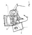
- FIG. 1 shows apparatus for detecting a position of the mechanical interaction in the form of a fabric keyboard
- FIG. 2 shows an alternative application for the detection apparatus
- FIG. 3 illustrates an interface device
- FIG. 4 shows internal components of the interface device of FIG. 3 ;
- FIG. 5 illustrates a characteristic of a known sensor
- FIG. 6 illustrates an embodiment of the present invention
- FIG. 7 illustrates a knitting process
- FIG. 8 shows an example of a knit produced by the process illustrated in FIG. 7 ;
- FIG. 9 shows the knit of FIG. 8 in greater detail
- FIG. 10 illustrates a response characteristic of a preferred embodiment.
- FIG. 1 A first figure.
- FIG. 1 shows a fabric keyboard, which may be considered as an example of apparatus for detecting the position of a mechanical interaction.
- a fabric keyboard 101 is communicating with a hand-held processor 102 via an interface device 103 .
- the keyboard 101 it is possible to use the keyboard 101 so as to provide alphanumeric characters to the processing device 102 .
- FIG. 2 shows an alternative application for the detection apparatus.
- the detecting apparatus 201 is included as part of a carrying strap 202 of a rucksack.
- an audio player is restrained within a pocket 203 and audio signals are conveyed to a user via headphones 204 .
- detection apparatus embodying the present invention may also be deployed in items of clothing, such as jackets or trousers etc in addition to items of apparel such as bags or rucksacks.
- FIG. 3 shows a preferred application in which an interface device 301 is provided having a processing circuit with analog ports and control ports.
- the processing circuit includes a housing 302 for enclosing the processing circuit and for supporting a first physical interface 303 and a second physical interface 304 .
- the first physical interface 302 is connected to the analog ports of the processing circuit and is also connectable to a fabric sensor 305 , embodying the preferred aspects of the present invention.
- the second physical interface 304 is connected to the control ports of the processing circuit and is also connectable to an electronic device, such as an audio player 306 , such that when an electronic device is connected to the interface device 301 it is possible for the electronic device 306 to be controlled by manual operation of the fabric sensor 305 .
- the first physical interface may take the form of a socket 303 into which a plug 307 is received; the plug itself receiving connections 308 from the fabric sensor 305 .
- the second physical interface may take the form of a cable 309 that extends from the housing 302 so as to be connected to a plug 304 insertable into the electronic device 306 .
- FIG. 4 shows internal components of the interface device 301 .
- Interface 307 is shown extending from the housing 302 as a connection to the left and interface 304 is shown as connections extending from the right of the housing 302 .
- the number of connections established by interface 304 may vary depending upon the particular application.
- a processor 401 (preferably a microcontroller) supplies voltages to connectors 402 .
- Resistors 406 and 407 have resistances that are substantially similar to the resistance of the fabric detector, measured from a first conducting layer to the opposite conducting layer when a typical target pressure has been applied.
- the detection process is controlled by a program executed by the microcontroller 401 that is in turn configured to supply output voltages at pins 405 and to receive analog input voltages at input pins 407 via high impedance buffers 409 and 410 .
- FIG. 5 illustrates that it is possible to perform a test on a known sensor to determine the level of pressure required over an active area of the sensor.
- a resulting graph for a known five-layer system is illustrated in FIG. 5 .
- Activation force is plotted along the x axis 501 representing the amount of pressure required in order for activation to occur.
- Frequency that is the number of presses that scored a particular level of activation force, is plotted along the y axis 502 .
- the resulting distribution 503 is relatively spread-out over a range of force showing that the sensitivity of the device is quite variable which as previously described, may result in less than perfect operation when supplying data to a processing device.
- FIG. 6 illustrates a detection apparatus embodying the present invention, in exploded view.
- the detector has a first fabric conducting layer 601 having electrically conducting fibres, electrically conducting tracks 602 , 603 and terminals 604 connectable to the processing circuit shown in FIG. 4 .
- the conductive fibres are preferably a conductive monofilament.
- a second fabric layer 605 has conducting fibres and insulating fibres.
- This second fabric layer is a knitted fabric having a substantially smooth back 606 and an irregular front 607 .
- This layout is preferably a knitted tricot construction with both conducting and insulating monofilaments.
- a third separating layer 608 is constructed from an insulator with openings therein to allow conduction to occur between said openings when pressure is applied.
- this separating layer is implemented as a net, possibly constructed from a knitted plastics material.
- a forth fabric conducting layer 609 is similar to the first fabric conducting layer, having electrically conducting fibres, electrically conducting tracks 610 , 611 and terminals, again connectable to a processing circuit, such as that shown in FIG. 4 .
- the knitted fabric 606 is positioned such that its irregular front surface is in contact with the first conducting layer and its smooth back surface is in contact with the separating layer. In this way, a good electrical contact is provided between the knitted layer and the insulating layer, thereby providing a degree of uniformity, such that the activation force is spread over a much lower range compared to the known five layer systems.
- the irregular front face of the knitted layer is less critical to operational sensitivity. It provides an adequate degree of separation, but at the same time gives good electrical contact when pressure is applied, given the high conductivity of the first layer.
- FIG. 7 shows an example of a knitted layer 606 .
- the knitted layer 606 is produced by a process of Raschel or Tricottype warp knitting.
- the warp knit is produced on a flat bed machine with several independent yarns 701 to 704 running along the length of the warp.
- the number of threads present defines the number of wales which in turn defines the width of the fabric as illustrated by arrow 705 .
- the knitting process involves defining loops, such as loop 706 with each row of loops defining a single course.
- the courses extend along the length of arrow 707 .
- the knitting process involves pulling a thread, such as thread 708 through a loop, such as loop 706 .
- the loops lie flat against a bed 709 and the threads and resulting knots extend therefrom in an upwards direction.
- the upper surface as shown in FIG. 7 results in the generation of the technical face with the under surface, supported by bed 709 representing the technical back.
- the technical back presents a substantially smooth plane which, in accordance with this invention is placed in contact with the insulating separating layer.
- the irregular face is placed in contact with the first conducting layer.
- this close co-operation with the conducting layer ensures that good electrical contact is maintained when pressure is applied, irrespective of the position of the pressure.
- the irregularities of the knitted face are compensated by the smooth attributes of the first conducting layer.
- the irregularities of the insulating layer 608 are compensated by the smooth presence of the back of the knitted layer 607 .
- the attributes of the knitted layer 607 namely the presence of a technical face with irregularities and the presence of a technical back with a smooth presentation, to enable a four-layer detector to be produced which has desirable properties in terms of the amount of force required in order for contact to be achieved.
- FIG. 8 shows an example of a knit produced by the process identified in FIG. 7 .
- the knit includes insulating yarns 801 and conducting yarns 802 .
- the conducting yarns ensure that it is possible for electrical current to flow in the plane of the knit. In this way, it is possible for the knit to provide the required functionality within the detector.
- insulating yarns ensure that insulation is maintained in situations when manual pressure has not been applied.
- the plane back surface facilitates good conduction.
- the raised knots 803 provide the required level of insulation when pressure is not being applied.
- FIG. 9 shows a close up view of the knitted construction.
- raised loops 803 are present which give the knitted structure a three-dimensionality and ensure that separation is maintained between the conductive layers.
- the under back surface is substantially smooth and thereby facilitates a uniform response.
- the raised front surface due to the presence of loops 803 , ensures that spacing is provided so as to ensure insulation and non-conduction in the absence of pressure being applied to the detector.
- FIG. 10 illustrates the desirable properties of the four-layer system.
- Axis 801 and 802 are substantially similar to axes 501 and 502 in FIG. 5 .
- the response curve 803 is significantly different from response curve 503 .
- the active range that is the range over which activation takes place, is relatively narrow resulting in the presence of a peak where most activations occur.
- the detector has a response which is far less variable therefore it is easier from an operative to become familiar with the amount of force required in order for activation to occur.
- the responsiveness of the detector ensures that the detector is easier to calibrate and as such its range of application may be increased.
Abstract
Description
Claims (21)
Applications Claiming Priority (2)
| Application Number | Priority Date | Filing Date | Title |
|---|---|---|---|
| GB0708439.5A GB2448893B (en) | 2007-05-02 | 2007-05-02 | Position detection |
| GB0708439.5 | 2007-05-02 |
Publications (2)
| Publication Number | Publication Date |
|---|---|
| US20080289886A1 US20080289886A1 (en) | 2008-11-27 |
| US8089336B2 true US8089336B2 (en) | 2012-01-03 |
Family
ID=38171024
Family Applications (1)
| Application Number | Title | Priority Date | Filing Date |
|---|---|---|---|
| US12/114,179 Expired - Fee Related US8089336B2 (en) | 2007-05-02 | 2008-05-02 | Position detection |
Country Status (2)
| Country | Link |
|---|---|
| US (1) | US8089336B2 (en) |
| GB (1) | GB2448893B (en) |
Cited By (5)
| Publication number | Priority date | Publication date | Assignee | Title |
|---|---|---|---|---|
| US20120120009A1 (en) * | 2009-03-25 | 2012-05-17 | Peratech Limited | Sensor |
| US20150000425A1 (en) * | 2012-02-13 | 2015-01-01 | Nissan Motor Co., Ltd. | Sheet pressure sensor |
| US20160135744A1 (en) * | 2011-05-20 | 2016-05-19 | The Regents Of The University Of California | Fabric-based pressure sensor arrays and methods for data analysis |
| US20190219460A1 (en) * | 2016-06-30 | 2019-07-18 | Lg Innotek Co., Ltd. | Pressure sensor and pressure sensing device comprising same |
| US10591273B2 (en) * | 2017-10-20 | 2020-03-17 | C.R.F. Società Consortile Per Azioni | Deformation detecting device comprising a multi-functional fabric with flocked conductive weft yarns |
Families Citing this family (17)
| Publication number | Priority date | Publication date | Assignee | Title |
|---|---|---|---|---|
| US8194398B2 (en) * | 2007-05-01 | 2012-06-05 | Daley Iii Charles A | Bag computer system and bag apparatus |
| US8605416B2 (en) * | 2007-05-01 | 2013-12-10 | Charles A. Daley, III | Bag computer two part display panel |
| US8553401B2 (en) * | 2007-05-01 | 2013-10-08 | Charles A. Daley, III | Bag computer computing unit panel and display panel |
| US8830666B2 (en) * | 2007-05-01 | 2014-09-09 | Charles A. Daley, III | Bag computer sliding deployment display panel assembly |
| US20090225509A1 (en) * | 2007-05-01 | 2009-09-10 | Daley Iii Charles A | Bag computer two part display panel |
| US8125770B2 (en) * | 2007-05-01 | 2012-02-28 | Daley Iii Charles A | Bag computer input output device |
| US8867199B2 (en) * | 2010-01-04 | 2014-10-21 | Charles A. Daley, III | Bag computer two panel propping computer |
| EP2523081B1 (en) * | 2010-01-06 | 2019-09-18 | Huawei Device Co., Ltd. | Method and terminal for displaying picture/interface |
| US8587422B2 (en) | 2010-03-31 | 2013-11-19 | Tk Holdings, Inc. | Occupant sensing system |
| DE102011006448A1 (en) | 2010-03-31 | 2011-10-06 | Tk Holdings, Inc. | steering wheel sensors |
| US8983732B2 (en) | 2010-04-02 | 2015-03-17 | Tk Holdings Inc. | Steering wheel with hand pressure sensing |
| DE102011006649B4 (en) | 2010-04-02 | 2018-05-03 | Tk Holdings Inc. | Steering wheel with hand sensors |
| US20120275102A1 (en) * | 2010-11-30 | 2012-11-01 | Daley Iii Charles A | Bag computer display panel frame |
| WO2013154720A1 (en) | 2012-04-13 | 2013-10-17 | Tk Holdings Inc. | Pressure sensor including a pressure sensitive material for use with control systems and methods of using the same |
| JP6260622B2 (en) | 2012-09-17 | 2018-01-17 | ティーケー ホールディングス インク.Tk Holdings Inc. | Single layer force sensor |
| US20140313653A1 (en) * | 2013-04-19 | 2014-10-23 | Charles A. Daley, III | Bag computer system and bag apparatus |
| CN111369764A (en) * | 2015-05-15 | 2020-07-03 | J·布拉施有限公司 | System and method for monitoring people by simulating multi-region pressure sensitive pad |
Citations (5)
| Publication number | Priority date | Publication date | Assignee | Title |
|---|---|---|---|---|
| WO2001075924A1 (en) | 2000-03-30 | 2001-10-11 | Electrotextiles Company Limited | Detector constructed from electrically conducting fabric |
| WO2002052391A2 (en) | 2000-12-22 | 2002-07-04 | Eleksen Limited | Manually operable remote controller |
| US20020180578A1 (en) | 1999-05-20 | 2002-12-05 | Eleksen Limited | Detector constructed from fabric |
| WO2005091319A1 (en) | 2004-03-18 | 2005-09-29 | Eleksen Limited | Sensor response |
| US7301435B2 (en) * | 2000-05-18 | 2007-11-27 | Peratech Limited | Flexible switching devices |
-
2007
- 2007-05-02 GB GB0708439.5A patent/GB2448893B/en not_active Expired - Fee Related
-
2008
- 2008-05-02 US US12/114,179 patent/US8089336B2/en not_active Expired - Fee Related
Patent Citations (7)
| Publication number | Priority date | Publication date | Assignee | Title |
|---|---|---|---|---|
| US20020180578A1 (en) | 1999-05-20 | 2002-12-05 | Eleksen Limited | Detector constructed from fabric |
| US6504531B1 (en) * | 1999-05-20 | 2003-01-07 | Eleksen Limited | Detecting mechanical interactions |
| US6714117B2 (en) * | 1999-05-20 | 2004-03-30 | Eleksen Limited | Detector constructed from fabric |
| WO2001075924A1 (en) | 2000-03-30 | 2001-10-11 | Electrotextiles Company Limited | Detector constructed from electrically conducting fabric |
| US7301435B2 (en) * | 2000-05-18 | 2007-11-27 | Peratech Limited | Flexible switching devices |
| WO2002052391A2 (en) | 2000-12-22 | 2002-07-04 | Eleksen Limited | Manually operable remote controller |
| WO2005091319A1 (en) | 2004-03-18 | 2005-09-29 | Eleksen Limited | Sensor response |
Cited By (9)
| Publication number | Priority date | Publication date | Assignee | Title |
|---|---|---|---|---|
| US20120120009A1 (en) * | 2009-03-25 | 2012-05-17 | Peratech Limited | Sensor |
| US9182845B2 (en) * | 2009-03-25 | 2015-11-10 | Peratech Holdco Limited | Sensor |
| US20160135744A1 (en) * | 2011-05-20 | 2016-05-19 | The Regents Of The University Of California | Fabric-based pressure sensor arrays and methods for data analysis |
| US11617537B2 (en) * | 2011-05-20 | 2023-04-04 | The Regent Of The University Of California | Fabric-based pressure sensor arrays including intersecting elongated conductive strips on opposite sides of a textile sheet |
| US20150000425A1 (en) * | 2012-02-13 | 2015-01-01 | Nissan Motor Co., Ltd. | Sheet pressure sensor |
| US9645021B2 (en) * | 2012-02-13 | 2017-05-09 | Nissan Motor Co., Ltd. | Sheet pressure sensor |
| US20190219460A1 (en) * | 2016-06-30 | 2019-07-18 | Lg Innotek Co., Ltd. | Pressure sensor and pressure sensing device comprising same |
| US11029222B2 (en) * | 2016-06-30 | 2021-06-08 | Lg Innotek Co., Ltd. | Pressure sensor having conductive material extending between non-porous and porous regions and pressure sensing device comprising same |
| US10591273B2 (en) * | 2017-10-20 | 2020-03-17 | C.R.F. Società Consortile Per Azioni | Deformation detecting device comprising a multi-functional fabric with flocked conductive weft yarns |
Also Published As
| Publication number | Publication date |
|---|---|
| GB2448893B (en) | 2012-01-11 |
| GB2448893A (en) | 2008-11-05 |
| US20080289886A1 (en) | 2008-11-27 |
| GB0708439D0 (en) | 2007-06-06 |
Similar Documents
| Publication | Publication Date | Title |
|---|---|---|
| US8089336B2 (en) | Position detection | |
| US8169295B2 (en) | Manually operable position sensor | |
| US6452479B1 (en) | Detector contructed from fabric | |
| KR101051311B1 (en) | Textile Input Device | |
| TWI285227B (en) | Pressure sensible textile and pressure sensible device thereof | |
| US8373079B2 (en) | Woven manually operable input device | |
| US7230610B2 (en) | Keypad in textiles with capacitive read-out circuit | |
| US8050733B2 (en) | Sensor system, garment and heart rate monitor | |
| US6437258B1 (en) | Detector constructed from fabric having planes with differing conductance | |
| CN109642833A (en) | The equipment based on fabric that band effectively senses | |
| Roh et al. | Robust and Reliable Fabric, Piezoresistive Multitouch Sensing Surfaces for Musical Controllers. | |
| US20030146902A1 (en) | Manual input apparatus and processor | |
| US20220183628A1 (en) | Device for determining effects of aging of a wearable device | |
| US20020135457A1 (en) | Foldable alpha numeric keyboard | |
| CN114296574A (en) | Fabric sensing device | |
| Ismar et al. | Towards embroidered circuit board from conductive yarns for E-textiles | |
| US20180323524A1 (en) | Electrical Connections And their Use in Wearables and Other Applications | |
| CN110941371B (en) | Capacitive touch sensor, article including the same, and method of detecting touch events | |
| US10566151B1 (en) | Items with fabric domes | |
| Leśnikowski | New Kind of TextileTransmission Line with an Impedance of 50 Ohms | |
| CN213022056U (en) | Pressure sensor, pressure sensing system and fabric piece | |
| Linz et al. | New interconnection technologies for the integration of electronics on textile substrates | |
| US20070063835A1 (en) | Wearable variable resistor | |
| Parkova et al. | Integration of flexible keypad into clothing | |
| WO2021106227A1 (en) | Contact pressure sensor, knitted article equipped with same, and method for producing contact pressure sensor |
Legal Events
| Date | Code | Title | Description |
|---|---|---|---|
| AS | Assignment |
Owner name: PERATECH LIMITED, UNITED KINGDOM Free format text: ASSIGNMENT OF ASSIGNORS INTEREST;ASSIGNOR:BURKITT, JOHN;REEL/FRAME:021366/0861 Effective date: 20080722 |
|
| STCF | Information on status: patent grant |
Free format text: PATENTED CASE |
|
| FEPP | Fee payment procedure |
Free format text: PAYOR NUMBER ASSIGNED (ORIGINAL EVENT CODE: ASPN); ENTITY STATUS OF PATENT OWNER: LARGE ENTITY |
|
| AS | Assignment |
Owner name: TOMTOM INTERNATIONAL B.V., NETHERLANDS Free format text: ASSIGNMENT OF ASSIGNORS INTEREST;ASSIGNOR:PERATECH LIMITED;REEL/FRAME:034171/0037 Effective date: 20140508 |
|
| AS | Assignment |
Owner name: WEARABLE TECHNOLOGY LIMITED, UNITED KINGDOM Free format text: ASSIGNMENT OF ASSIGNORS INTEREST;ASSIGNOR:TOMTOM INTERNATIONAL B.V.;REEL/FRAME:035446/0851 Effective date: 20150325 |
|
| REMI | Maintenance fee reminder mailed | ||
| FPAY | Fee payment |
Year of fee payment: 4 |
|
| SULP | Surcharge for late payment | ||
| FEPP | Fee payment procedure |
Free format text: MAINTENANCE FEE REMINDER MAILED (ORIGINAL EVENT CODE: REM.); ENTITY STATUS OF PATENT OWNER: LARGE ENTITY |
|
| LAPS | Lapse for failure to pay maintenance fees |
Free format text: PATENT EXPIRED FOR FAILURE TO PAY MAINTENANCE FEES (ORIGINAL EVENT CODE: EXP.); ENTITY STATUS OF PATENT OWNER: LARGE ENTITY |
|
| STCH | Information on status: patent discontinuation |
Free format text: PATENT EXPIRED DUE TO NONPAYMENT OF MAINTENANCE FEES UNDER 37 CFR 1.362 |
|
| FP | Lapsed due to failure to pay maintenance fee |
Effective date: 20200103 |