US8089321B2 - Fluctuation oscillator, fluctuation oscillating system, observation device and control system - Google Patents
Fluctuation oscillator, fluctuation oscillating system, observation device and control system Download PDFInfo
- Publication number
- US8089321B2 US8089321B2 US12/673,797 US67379708A US8089321B2 US 8089321 B2 US8089321 B2 US 8089321B2 US 67379708 A US67379708 A US 67379708A US 8089321 B2 US8089321 B2 US 8089321B2
- Authority
- US
- United States
- Prior art keywords
- signal
- stochastic
- fluctuation
- output
- fluctuation oscillator
- Prior art date
- Legal status (The legal status is an assumption and is not a legal conclusion. Google has not performed a legal analysis and makes no representation as to the accuracy of the status listed.)
- Active, expires
Links
Images


Classifications
-
- G—PHYSICS
- G06—COMPUTING; CALCULATING OR COUNTING
- G06G—ANALOGUE COMPUTERS
- G06G7/00—Devices in which the computing operation is performed by varying electric or magnetic quantities
- G06G7/12—Arrangements for performing computing operations, e.g. operational amplifiers
-
- H—ELECTRICITY
- H03—ELECTRONIC CIRCUITRY
- H03K—PULSE TECHNIQUE
- H03K3/00—Circuits for generating electric pulses; Monostable, bistable or multistable circuits
- H03K3/02—Generators characterised by the type of circuit or by the means used for producing pulses
- H03K3/027—Generators characterised by the type of circuit or by the means used for producing pulses by the use of logic circuits, with internal or external positive feedback
- H03K3/03—Astable circuits
- H03K3/0315—Ring oscillators
Definitions
- the present invention relates to a fluctuation oscillator, a fluctuation oscillating system, an observation device and a control system.
- a CPG is an oscillator based on a neural network which autonomously outputs a periodic signal to the musculoskeletal system which controls the activities of walking, respiratory and circulatory organs, and the like, in a living organism.
- Known methods of artificially creating a CPG are a method which creates a CPG signal by computer simulation, and a method which joins together conventional oscillators, such as liquid crystal oscillators, Hartley oscillators, Clapp oscillators, astable multivibrators, in a plurality of chains, and the like.
- SCIENCE 315, 1416 (2007) describes technology for artificially creating a CPG by linking together a plurality of conventional oscillators in a chain, and using signals output from this CPG to control a robot having a multiple degree-of-freedom joint.
- Non-Patent Document 1 a conventional oscillator is instable in respect of noise, and moreover, the drive voltage of the semiconductor elements must be set to a high level in order to combat noise, thus making it difficult to achieve a CPG with low power consumption.
- the oscillation frequency is fixed by the circuit constant, and since the oscillation frequency cannot be changed flexibly and autonomously, then there has been a problem in that such an oscillator is not suitable as a CPG which is required to perform cooperative operation between oscillators.
- the object of the present invention is to resolve the problems described above.
- the object of the present invention is to provide a fluctuation oscillator and a fluctuation oscillating system which has low power consumption, which is robust in respect of noise signals, and which can change the oscillation frequency flexibly and autonomously, and an observation device and control system using same.
- the object of the present invention is to provide a fluctuation oscillator and a fluctuation oscillating system, and an observation device and control system using same, which are useful in creating a CPG artificially.
- the fluctuation oscillator according to one aspect fluctuation oscillator the present invention comprises a plurality of stochastic resonators which apply fluctuation to an input signal by superimposing a noise signal thereon, compare the resulting signal with a threshold value, and then perform differentiation to output a pulse signal, the plurality of stochastic resonators being coupled unidirectionally in a ring-like form in such a manner that an output terminal of one stochastic resonator is connected to an input terminal of the stochastic resonator of the following stage, and an input terminal of the one stochastic resonator is connected to an output terminal of the stochastic resonator of the preceding stage.
- the fluctuation oscillating system comprises a first and a second fluctuation oscillator, each being constituted by a fluctuation oscillator as described above, and the input terminal of one stochastic resonator constituting the first fluctuation oscillator being connected to the output terminal of one stochastic resonator constituting the second fluctuation oscillator.
- the observation device and control system use the fluctuation oscillator described above.
- FIG. 1 shows a general schematic view of a fluctuation oscillator according to an embodiment of the present invention.
- FIG. 2 is a diagram showing the composition of a stochastic resonator shown in FIG. 1 .
- FIGS. 3A to 3D are illustrative diagrams of the operational principle of a fluctuation oscillator.
- FIGS. 4A and 4B are graphs showing the coupling constant.
- FIG. 5 shows a circuit diagram of the stochastic resonator shown in FIG. 2 .
- FIG. 6 is a diagram showing the comparator and differentiation circuit shown in FIG. 4 .
- FIG. 7 shows a graph of Equation (3).
- FIGS. 8A to 8C are illustrative diagrams of the operation of the differentiation circuit.
- FIG. 9 is an illustrative diagram of a fluctuation oscillator.
- FIG. 10 is a graph showing simulation results of carrying out a simulation of the operation of a fluctuation oscillator using Equation (9).
- FIG. 11 is a table showing the values of various parameters in Equation (9).
- FIG. 12 is a graph showing the power spectrum of the output signal of a stochastic resonator when the intensity of the noise signal of the stochastic resonator shown in FIG. 2 is changed.
- FIG. 13 is a graph showing the relationship between the S/N ratio of the output signal of the stochastic resonator shown in FIG. 2 and the intensity of the noise signal.
- FIGS. 14A and 14B show waveform diagrams of the fluctuation oscillator shown in FIG. 1 .
- FIGS. 15A and 15B show waveform diagrams of the signal output from the stochastic resonator in the fluctuation oscillator shown in FIG. 1 .
- FIGS. 16A to 16D are waveform diagrams showing a signal output when the intensity of the noise signal is changed in the fluctuation oscillator shown in FIG. 1 .
- FIG. 17 is a graph showing the frequency dependence of the input/output cross-correlation function of the fluctuation oscillator shown in FIG. 1 .
- FIGS. 18A to 18C show waveform diagrams of a signal output from a fluctuation oscillator when the frequency of the trigger signal is changed in the fluctuation oscillator shown in FIG. 1 .
- FIGS. 19A to 19C show waveform diagrams of a signal output from a fluctuation oscillator when the frequency of the trigger signal is changed in the fluctuation oscillator shown in FIG. 1 .
- FIG. 20 is a diagram showing the composition of a fluctuation oscillating system.
- FIGS. 21A to 21C show waveform diagrams of a signal output from a fluctuation oscillating system.
- FIG. 22 is a diagram showing the composition of an observation device.
- FIG. 23 is a diagram showing the composition of a control system.
- FIG. 24 is an external schematic drawing of a snake-like robot.
- FIGS. 25A and 25B are cross-sectional diagrams of a body portion.
- FIG. 26 is a diagram showing a control system according to a further embodiment of the present invention.
- FIGS. 27A to 27C show waveform diagrams of a fluctuation oscillator constituting the control system shown in FIG. 26 .
- FIGS. 28A to 28D are waveform diagrams of an output signal from a threshold value judgment unit of a stochastic resonator constituting a fluctuation oscillator.
- FIG. 29 is a diagram showing a simulation model of a snake-like robot used in a simulation.
- FIGS. 30A to 30D are graphs showing the movement of the simulation model shown in FIG. 29 .
- FIG. 1 shows a general schematic drawing of a fluctuation oscillator 10 according to an embodiment of the present invention.
- the present fluctuation oscillator 10 comprises four stochastic resonators 20 - 1 to 20 - 4 which are coupled unidirectionally in a ring-like form. Where a certain stochastic resonator is not specified in particular, reference is made simply to stochastic resonator(s) 20 . Furthermore, the number of stochastic resonators 20 is not limited to four, and may be two, three or five or more.
- unidirectional coupling means that the signals flow in one direction.
- the stochastic resonators 20 are connected in a ring-like form by means of the output terminal of one stochastic resonator being connected to the input terminal of another adjacent stochastic resonator 20 and the input terminal of one stochastic resonator 20 being connected to the output terminal of another adjacent stochastic resonator, in such a manner that the output terminal of the stochastic resonator 20 - 1 is connected to the input terminal of the stochastic resonator 20 - 2 , and the input terminal of the stochastic resonator 20 - 1 is connected to the output terminal of the stochastic resonator 20 - 4 . Consequently, the signal flowing in the fluctuation oscillator 10 circulates successively through the stochastic resonator 20 - 1 to 20 - 4 .
- FIG. 2 is a diagram showing the composition of a stochastic resonator 20 shown in FIG. 1 .
- the stochastic resonator 20 comprises a noise generator 21 , a signal adder 22 , a threshold value judgment unit 23 , a differentiator 24 and an output unit 25 .
- the noise generator 21 is, for example, constituted by a function generator which generates various noise signals, such as Gaussian white noise, thermal noise, or the like.
- the signal adder 22 inputs n types of input signal (where n is a positive integer) and a noise signal output from the noise generator 21 , multiplexes (adds) the input noise signal and n types of input signals, applies a fluctuation to this input signal, and output same to the threshold value judgment unit 23 .
- the n types of input signals are input via the input terminals 221 to 22 n.
- a trigger signal forming an oscillator trigger for example, is input to the input terminal 221 , and an output signal from the stochastic resonator 20 connected in the prior stage (the upstream side in the signal path) is input to the input terminal 222 .
- the trigger signal and the signal output from another stochastic resonator 20 may also be input to another input terminal.
- the threshold value judgment unit 23 compares the signal to which fluctuation has been applied by the signal adder 22 with a prescribed threshold value, and outputs a pulse signal which has a high level when this signal is equal to or greater than the threshold value, and outputs a pulse signal which has a low level when this signal is smaller than the threshold value.
- the threshold value has hysteresis and therefore the threshold value when the pulse signal changes from low level to high level and the threshold value when the pulse signal changes from high level to low level are different. Hysteresis can be imparted readily to the threshold value by composing the threshold value judgment unit 23 from a Schmitt trigger circuit, for example.
- the differentiator 24 differentiates the signal output from the threshold value judgment unit 23 .
- the output unit 25 adjusts the level of the signal output from the differentiator 24 .
- the stochastic resonator 20 shown on the left-hand side in FIG. 2 is expressed by using the symbols on the right-hand side in FIG. 2 .
- the noise signal intensity, the time constant of the differentiator 24 , and the coupling constant have the same values in each of the respective stochastic resonators 20 , and are set to values previously established in such a manner that the fluctuation oscillator 10 is able to oscillate.
- FIGS. 3A to 3D are illustrative diagrams of the operating principles of the fluctuation oscillator 10 ;
- FIG. 3A shows the signal S 1 to which noise output from the signal adder 22 has been added, and the variation in the threshold values Vth 1 , Vth 2 (Vth 1 >Vth 2 ) of the threshold value judgment unit 23 .
- FIG. 3B shows a signal S 3 output from the threshold value judgment unit 23 .
- FIG. 3C shows a signal S 4 output from the differentiator 24 .
- FIG. 3D is an enlarged diagram of the signal S 4 .
- the signal S 1 exceeds the threshold value Vth 1 in the portion indicated by arrow YU in FIG. 3A . If the signal S 1 exceeds the threshold value Vth 1 , then the signal S 3 is switched from low level (VL) to high level (VH). By this means, the stochastic resonator 20 switches on. Furthermore, the signal S 1 is lower than the threshold value Vth 2 in the portion indicated by the arrow YD in FIG. 3A . When the signal S 1 is lower than the threshold value Vth 2 , then the signal S 3 switches from high level (VH) to low level (VL). By this means, the stochastic resonator 20 switches off.
- the signal S 3 is differentiated by the differentiator 24 and output as signal S 4 .
- the signal S 4 is attenuated to a ground level by the time constant of the differentiator 24 and is input to the stochastic resonator 20 connected in the next stage.
- the signal S 4 is circulated recursively in the fluctuation oscillator 10 .
- the recursively circulated signal S 4 is attenuated over time, by the action of the differentiators 24 of the respective stochastic resonators 20 of the fluctuation oscillator 10 . If the time since the switching on of the stochastic resonator 20 is short, then the intensity of the signal S 4 is strong. If the intensity of signal S 4 is strong, then the respective stochastic resonators 20 connected in a ring-like form are all in an on state.
- a signal S 4 having a peak in the negative direction is output from the stochastic resonator 20 .
- the other stochastic resonators 20 switch off and signals S 4 having virtually simultaneous peaks in the negative direction are output from all of the stochastic resonators 20 .
- the fluctuation oscillator 10 oscillates due to the respective stochastic resonators 20 repeatedly switching between an on state and an off state as described above.
- the signal S 1 is a signal having randomness to which fluctuation has been applied by the noise signal. Therefore, the time interval from switching on until switching off is determined stochastically and hence is not exactly uniform in each of the stochastic resonators 20 . However, the greater the intensity of the signal S 1 , the greater the probability of a stochastic resonator 20 switching off, and therefore this time interval becomes shorter, the greater the intensity of the signal S 1 . In other words, if the intensity of the noise signal is adjusted to a suitable value, then in overall terms, the time interval becomes more dependent on the intensity of the signal S 1 rather than the randomness of the signal S 1 . Therefore, the fluctuation oscillator 10 oscillates at a frequency corresponding to the intensity of the signal S 1 .
- the time interval until switching off is dependent on the intensity of the input signal, which includes the intensity of the noise signal, then if the intensity of the input signal changes, the fluctuation oscillator 10 is self-excited to oscillate at a corresponding frequency.
- the time constant of the differentiator 24 becomes longer, so the time interval from the stochastic resonators 20 switching on until switching off becomes longer, and the frequency of the output signal from the fluctuation oscillator 10 becomes longer. Consequently, by adjusting the time constant of the stochastic resonators 20 to a suitable value, it is possible to adjust the frequency of the output signal from the fluctuation oscillator 10 to a desired frequency value.
- FIGS. 4A and 4B are graphs showing the coupling constant, in which FIG. 4A is a graph showing the oscillation frequency of the output signal from the fluctuation oscillator 10 , and FIG. 4B is a graph showing the peak power spectrum intensity of the output signal from the fluctuation oscillator 10 .
- the vertical axis represents the oscillation frequency and the horizontal axis represents the intensity of the noise signal.
- the vertical axis represents the peak of the power spectrum intensity of the output signal from the fluctuation oscillator 10
- the horizontal axis represents the intensity of the noise signal.
- the coupling constant indicates the extent to which one stochastic resonator is able to transmit a signal to an adjacent stochastic resonator, and a more concrete description is provided hereinafter.
- the peak of the power spectrum intensity of the output signal from the fluctuation oscillator 10 increases.
- the peak power spectrum intensity of the output signal changes by tracing an upwardly convex curve with respect to the intensity of the noise signal, and if the intensity of the noise signal becomes excessively low or excessively high, then the power spectrum intensity of the output signal becomes weak.
- the threshold value judgment unit 23 is taken to output a signal of high level if the signal S 1 exceeds the threshold value Vth 1 and to output a signal of low level if the signal S 1 is lower than the threshold value Vth 2 , but the composition is not limited to this and the threshold value judgment unit 23 may also output a signal of low level if the signal S 1 exceeds the threshold value Vth 1 and output a signal of high level if the signal S 1 is lower than threshold value Vth 2 .
- FIG. 5 shows a circuit diagram of a stochastic resonator 20 shown in FIG. 2 .
- the stochastic resonator 20 comprises a mixer circuit 201 which corresponds to the signal adder 22 in FIG. 2 , a comparator 202 which corresponds to the threshold value judgment unit in FIG. 2 , a differentiation circuit 203 which corresponds to the differentiator 24 in FIG. 2 , and an inverse amplification circuit 204 and output adjustment circuit 205 which correspond to the output unit 25 in FIG. 2 .
- the mixer circuit 201 comprises an adder circuit 201 - 1 and an inverting amplifier circuit 201 - 2 .
- the adder circuit 201 - 1 adds together a noise signal input to the input terminal TT 1 which corresponds to the input terminal 221 in FIG. 2 , an output signal from the stochastic resonator 20 which is connected in the previous stage and is input to the input terminal TT 2 corresponding to the input terminal 222 , and a trigger signal which is input to the input terminal TT 3 .
- the inverting amplifier circuit 201 - 2 amplifies the signal added by the adding circuit 201 - 1 .
- the adder circuit 201 - 1 comprises an operational amplifier A 11 .
- the negative terminal of the operational amplifier A 11 is connected to the input terminals TT 1 to TT 3 via the resistances R 11 to R 13 .
- the positive terminal of the operational amplifier A 11 is grounded.
- the operational amplifier A 11 is connected between the output terminal and the negative terminal via the resistance R 14 , thereby forming a negative feedback loop.
- the inverting amplifier circuit 201 - 2 comprises an operational amplifier A 12 .
- the negative terminal of the operational amplifier A 12 is connected to the output terminal of the operational amplifier A 11 via a resistance R 15 .
- the positive terminal of the operational amplifier A 12 is grounded.
- the output terminal of the operational amplifier A 12 and the negative terminal are connected via a resistance R 16 , thereby creating a negative feedback loop.
- the comparator 202 is constituted by a Schmitt trigger circuit comprising an operational amplifier A 21 .
- the positive terminal of the operational amplifier A 21 is grounded via a resistance R 22 .
- the output terminal and the positive terminal of the operational amplifier A 21 are connected via a resistance R 21 , thereby forming a positive feedback loop.
- the differentiation circuit 203 comprises a capacitor C 31 which is connected between the output terminal of the operational amplifier A 21 and the inverting amplifier circuit 204 , and a resistance R 31 , one end of which is connected to the capacitor C 31 and the other end of which is grounded.
- the inverting amplifier circuit 204 comprises an operational amplifier A 41 and inverts the polarity of the signal output from the differentiation circuit 203 .
- the negative terminal of the operational amplifier A 41 is connected to the capacitor C 31 via a resistance R 41 .
- the positive terminal of the operational amplifier A 41 is grounded.
- the output terminal and the negative terminal of the operational amplification A 41 are connected via a resistance R 42 .
- the inverting amplifier circuit 204 returns the polarity of the signal which has been inverted by the comparator 202 , to its original polarity.
- the output adjustment circuit 205 comprises a variable resistance VR 1 .
- the variable resistance VR 1 adjusts the level of the signal output from the inverting amplifier circuit 204 , by adjusting the resistance value, and thereby determines the coupling constant between the stochastic resonators 20 .
- the coupling constant is defined as “the peak intensity of the output signal from the stochastic resonator 20 connected in the previous stage divided by the threshold value of the threshold value judgment unit 23 when the stochastic resonator 20 switches on. In FIG. 3 , this is the positive-direction peak of the signal S 1 divided by the threshold value Vth 1 ”.
- the fluctuation oscillator 10 shown in FIG. 1 which has the composition described above operates as described below.
- a trigger signal is input to the stochastic resonator 20 - 1
- the stochastic resonator 20 - 1 switches on and outputs a signal S 4 having a sudden peak. Consequently, the stochastic resonator 20 - 2 which is connected on the downstream side switches on.
- a periodic signal based on a similar principle to a CPG, which is an oscillator based on a neural network that outputs a periodic signal autonomously and which is constituted by neurons which fire on the basis of a stochastic resonance phenomenon, and it is possible to provide an oscillator which is useful in artificially creating a CPG.
- Stochastic resonance phenomenon is a phenomenon whereby a synthesized signal is generated by synthesizing a noise signal with a weak sub-threshold signal, and when this synthesized signal is processed against the threshold value, the weak signal is transmitted to the output side.
- the SN ratio intensity of output signal/intensity of noise signal
- the intensity of the weak signal is uniform, and if the intensity of the noise signal is weak, then the probability of the synthesized signal exceeding the threshold value is small, and the SN ratio becomes small.
- the intensity of the noise signal is strong, then the overall intensity of the synthesized signal is strengthened randomly, the frequency with which the portion of strong intensity in the weak signal exceeds the threshold value increases, and the frequency with which the portion of weak intensity in the weak signal exceeds the threshold value decreases.
- the information of the weak signal is transmitted to the output side as the frequency with which the synthesized signal exceeds the threshold value. Therefore, if the intensity of the noise signal becomes strong, then the SN ratio increases. This SN ratio becomes a maximum when the noise signal has a certain intensity. Furthermore, if the intensity of the noise signal becomes yet stronger, then the noise signal becomes dominant in the synthesized signal and starts to exceed the threshold value randomly, and the SN ratio declines.
- FIG. 6 is a diagram showing the comparator 202 and the differentiation circuit 203 in FIG. 5 .
- the values R′, R′′, C in , R in shown in FIG. 6 correspond respectively to R 22 , R 21 , C 31 and R 31 shown in FIG. 5 .
- the signal v in input to the stochastic resonator 20 is added to the noise signal ⁇ , and is input to the v mix terminal in FIG. 6 .
- the signal v mix input to the v mix terminal is expressed by Equation (1).
- v mix ( t ) w ⁇ v in ( t )+ ⁇ ( t ) (1)
- ⁇ threshold value
- ⁇ response speed of operational amplifier
- a Sigmoid function is a function which outputs “0” when v mix (t) is smaller than the threshold value ⁇ and outputs “1” when v mix (t) is greater than the threshold value ⁇ , and this function represents the operation of the comparator 202 .
- v out (t) is input to the differentiation circuit 203 in the following stage, as v in2 .
- FIGS. 8A to 8C are illustrative diagrams of the operation of the differentiation circuit 203 ; wherein FIG. 8A is a waveform diagram of v in2 , FIG. 8B shows a differentiation circuit 203 , and FIG. 8C is a waveform diagram of v out2 , which is the output from the differentiation circuit 203 .
- the output from the comparator 202 , v in2 is a square wave as shown in FIG. 8A .
- v in2 passes through the differentiation circuit 203
- v in2 is attenuated by the time constant (CR) of the differentiation circuit 203
- the signal v out2 having a waveform such as that shown in FIG. 8C is output from the differentiation circuit 203 .
- C in C
- R in R.
- i ( t ) ( v in2 /R ) ⁇ exp( ⁇ t/CR )
- V out2 R ⁇ i ( t )
- Equation (5) the attenuation of the differentiation circuit 203 is expressed by Equation (5).
- v out2 v in2 ( t ) ⁇ exp( ⁇ t/CR ) (5)
- Equation (7) is obtained and this forms the master equation of the stochastic resonators 20 .
- the value t saw indicated below represents the attenuation time of the saw tooth wave. More specifically, taking the moment when the state of the comparator 202 switches from low level to high level (or from high level to low level) as 0, t saw represents the elapsed time until switching of the comparator occurs next.
- FIG. 9 is an illustrative diagram of the fluctuation oscillator 10 .
- the stochastic resonator 20 which make up the fluctuation oscillator 10
- the stochastic resonator 20 under particular consideration here is taken as the stochastic resonator under consideration C 20 .
- a ring feedback signal output from the stochastic resonator 20 of the previous stage is input to the stochastic resonator under consideration C 20 in addition to a noise signal and a trigger signal forming a weak signal.
- the intensity of the ring feedback signal varies depending on the coupling constant of the stochastic resonator 20 .
- the coupling constant is defined as “the peak intensity of the ring feedback signal divided by the threshold value when the stochastic resonator 20 switches on”. Therefore, if the coupling constant is equal to or greater than 1, then a ring feedback signal equal to or greater than the threshold value is input to the stochastic resonator under consideration C 20 .
- the signals which can be considered as input signals are: a trigger signal input from an external source, a ring loop back signal and a noise signal. If another fluctuation oscillator 10 is connected, the output signal from the fluctuation oscillator 10 is also included in the input signal.
- Equation (8) The value v i ′ shown in Equation (8) is the output signal from the comparator 202 of the stochastic resonator under consideration C 20 . Furthermore, ⁇ i shows the threshold value of the stochastic resonator under consideration C 20 .
- Equation (9) The value v i shown in Equation (9) is the output signal from the stochastic resonator under consideration C 20 , in other words, the signal after passing through the differentiation circuit 203 .
- w ij indicates the coupling constant between the respective nodes which input an input signal to the stochastic resonator under consideration C 20 , and the stochastic resonator under consideration C 20 .
- the suffix i of w ij indicates the stochastic resonator under consideration C 20
- j indicates the respective nodes which input an input signal to the stochastic resonator under consideration C 20
- n indicates the number of nodes which input an input signal to the stochastic resonator under consideration C 20 .
- Equation (9) is the master equation of the fluctuation oscillator 10 .
- FIG. 10 is a graph showing the simulation results of a simulation of the operation of the fluctuation oscillator 10 using the Equation (9).
- This simulation uses the fluctuation oscillator 10 constituted by four stochastic resonators 20 coupled in a ring-like form as shown in FIG. 10 , and white noise is added as a noise signal from an external source to the stochastic resonator under consideration C 20 only.
- the input signal and trigger signal from another fluctuation oscillator 10 are not input to the stochastic resonator under consideration C 20 .
- the values shown in FIG. 11 are applied to the various parameters in Equation (9).
- the upper graph indicates the output signal from the comparator 202 of the stochastic resonator under consideration C 20 and the lower graph indicates the output signal from the stochastic resonator under consideration C 20 .
- the stochastic resonator 20 shown in FIG. 2 inputs the noise signal output from the noise generator 21 to the signal adder 22 , but the composition is not limited to this and as indicated by the dotted line in FIG. 2 , it is also possible to input the noise signal to the threshold value judgment unit 23 and to alter the threshold value of the threshold value judgment unit 23 in accordance with the noise signal. In this case, the signal added up by the signal adder 22 is compared with the threshold value, but since a fluctuation is applied to the threshold value in accordance with the noise signal, then it is possible to produce a stochastic resonance phenomenon, similarly to the composition in FIG. 2 .
- FIG. 12 is a graph showing the power spectrum of the output signal of the stochastic resonator 20 when the intensity of the noise signal in the stochastic resonator 20 shown in FIG. 2 is changed. This graph was measured by using a sinusoidal wave having a frequency of 100 Hz and amplitude of 70 mV as a sinusoidal wave, and using Gaussian white noise as a noise signal. Furthermore, the threshold value judgment unit 23 outputs a 1V pulse signal, sets a threshold value of 100 mV and a threshold value hysteresis width of approximately 50 mV.
- the fourteen waveforms shown in FIG. 12 respectively show power spectra of the output signal of the stochastic resonator 20 when the intensity of the noise signal was 2.0V, 1.8V, 1.6V, 1.4V, 1.2V, 1.0V, 0.9V, 0.8V, 0.7V, 0.6V, 0.5V, 0.4V, 0.3V and 0V.
- the intensity of the noise signal increases, the intensity of the output signal also increases.
- the intensity of the noise signal is 0.5V to 2.0V, then a peak is observed in the vicinity of the frequency of 100 Hz.
- FIG. 13 is a graph showing the relationship between the S/N ratio of the output signal of the stochastic resonator 20 shown in FIG. 2 and the intensity of the noise signal, wherein the vertical axis represents the S/N ratio and the longitudinal axis represents the intensity of the noise signal. As shown in FIG. 13 , it can be seen that this graph changes so as to trace a bell shape. Consequently, it is possible to adjust the S/N ratio by adjusting the intensity of the noise signal.
- FIGS. 14A and 14B show waveform diagrams of the fluctuation oscillator 10 shown in FIG. 1 .
- FIG. 14A shows a waveform diagram of a trigger signal
- FIG. 14B shows a waveform diagram of the signal output from the stochastic resonator 20 - 4 .
- the threshold value of the respective stochastic resonators 20 is 100 mV
- the noise signal is Gaussian white noise having an intensity of 300 mV
- the trigger signal has an amplitude of 500 mV and a coupling constant of 5.
- a trigger signal is input to the stochastic resonator 20 - 1 , and a noise signal is also input.
- a sinusoidal wave having a frequency of 1 Hz and an amplitude of 500 mV was used as a trigger signal.
- a pulse signal is output from the respective stochastic resonators 20 , so as to follow the trigger signal. It can be seen that, if the input of the trigger signal is cut off when the time period TM 1 has passed, a pulse signal which has a pulse width some degree larger than the time period TM 1 is output repeatedly at a constant period, and the fluctuation oscillator 10 oscillates.
- FIGS. 15A and 15B show waveform diagrams of signals output from the threshold value judgment units 23 of the stochastic resonators 20 - 2 and 20 - 4 in the fluctuation oscillator 10 shown in FIG. 1 ;
- FIG. 15A is a waveform diagram of a signal output from the threshold value judgment unit 23 of the stochastic resonator 20 - 2 and
- FIG. 15B is a waveform diagram of a signal output from the threshold value judgment unit 23 of the stochastic resonator 20 - 4 .
- a noise signal is output at all times by the noise generator 21 in each of the stochastic resonators 20 .
- pulse signals having virtually the same phase, frequency and amplitude are output from the threshold value judgment units 23 of the stochastic resonators 20 - 2 and 20 - 4 . Therefore, it is clear that the same pulse signal is output from the threshold value judgment units 23 of the other stochastic resonators 20 - 1 and 20 - 3 , each of the stochastic resonators 20 oscillates in the same way, and the same signal can be extracted from each stochastic resonator.
- FIGS. 16A to 16D are waveform diagrams showing signals output when the intensity of the noise signal is changed in the fluctuation oscillator 10 shown in FIG. 1 ;
- FIGS. 16A to 16C show signals output from the stochastic resonator 20 - 4 when the intensity of the noise signal is 800 mV, 500 mV and 300 mV, and
- FIG. 16D shows a signal output from the stochastic resonator 20 - 4 when the intensity of the noise signal is initially 300 mV and then changes intermediately to 200 mV.
- a trigger signal is not input
- FIGS. 16C and 16D a trigger signal is input.
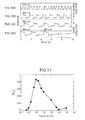
- FIG. 17 is a graph showing the frequency dependence of the input/output cross-correlation function of the fluctuation oscillator 10 shown in FIG. 1 .
- the vertical axis in FIG. 17 shows the absolute value of the cross-correlation value of the input/output signal, in other words, an indicator of the extent to which the output signal correlates to the input signal, and more specifically, shows the cross-correlation between the trigger signal and the output signal shown in FIGS. 18A to 18C and FIGS. 19A to 19C .
- the horizontal axis in FIG. 17 shows the frequency. As shown in FIG.
- this graph changes so as to trace an upwardly convex curve with a peak at 1 Hz, and it is found that the resonant frequency of the fluctuation oscillator 10 is 1 Hz. Furthermore, it can be seen that the graph traces a slow curve in the vicinity of the peak and has slow properties.
- FIGS. 18A to 18C and FIGS. 19A to 19C show waveform diagrams of signals which are output from the fluctuation oscillator 10 shown in FIG. 1 when the frequency of the trigger signal is changed in the fluctuation oscillator 10 ;
- FIGS. 18A to 18C show waveform diagrams when the frequency of the trigger signal is 0.1 Hz, 0.2 Hz and 1 Hz, respectively, and
- FIGS. 19A to 19C show waveform diagrams when the frequency of the trigger signal is 100 Hz, 500 Hz and 1 kHz, respectively.
- the upper curve represents the trigger signal and the lower curve represents the signal output from the fluctuation oscillator 10 .
- the trigger signal is a sinusoidal wave having an amplitude of 300 mV
- the noise signal is white Gaussian noise having an intensity of 300 mV.
- FIG. 18C and FIGS. 19A and 19B it can be seen that, when the frequency of the trigger signal is 1 Hz, 100 Hz and 500 Hz, then the frequency and the phase of the output signal from the fluctuation oscillator 10 and the trigger signal are almost the same, and the output signal is able to follow the trigger signal.
- FIGS. 18B and 18A it can be seen that as the frequency of the trigger signal decreases to 0.2 Hz and 0.1 Hz, then the frequency of the output signal becomes larger than the frequency of the trigger signal, and the output signal is not able to follow the trigger signal.
- FIG. 19C it can be seen that, if the frequency of the trigger signal is a high frequency of 1 kHz, then the pulses do not appear at a constant period and the fluctuation oscillator 10 cannot oscillate.
- the fluctuation oscillator 10 can oscillate so as to follow the trigger signal if the frequency of the trigger signal is within a uniform range, but if the frequency of the trigger signal is lower than a certain frequency, then the frequency of the output signal becomes greater than the frequency of the trigger signal, and the fluctuation oscillator 10 can no longer oscillate so as to follow the trigger signal. Furthermore, it can be seen that if the frequency of the trigger signal is greater than a certain frequency, then the fluctuation oscillator 10 can no longer oscillate.
- FIG. 20 is a diagram showing the composition of the present fluctuation oscillating system 100 .
- the fluctuation oscillating system 100 shown in FIG. 20 comprises three fluctuation oscillators 10 - 1 to 10 - 3 which are coupled unidirectionally.
- the respective fluctuation oscillators 10 each comprises four stochastic resonators 20 - 1 to 20 - 4 .
- the output terminal of the stochastic resonator 20 - 3 of the fluctuation oscillator 10 - 1 is connected to the input terminal of the stochastic resonator 20 - 2 of the fluctuation oscillator 10 - 3
- the output terminal of the stochastic resonator 20 - 3 of the fluctuation oscillator 10 - 2 is connected to the input terminal of the stochastic resonator 20 - 4 of the fluctuation oscillator 10 - 3
- the output signal from the fluctuation oscillator 10 - 1 is transmitted to the fluctuation oscillator 10 - 3
- the output signal from the fluctuation oscillator 10 - 2 is transmitted to the fluctuation oscillator 10 - 3 .
- an output signal is extracted from the stochastic resonator 20 - 3 of the fluctuation oscillator 10 - 3 .
- the fluctuation oscillator 10 - 3 outputs, as an output signal, a periodic signal which is affected by the output signal from the fluctuation oscillator 10 - 1 and the output signal from the fluctuation oscillator 10 - 2 , and therefore the fluctuation oscillator 10 - 3 is able to oscillate on the basis of a principle similar to that of a CPG, which oscillates autonomously due to the output from one neuron affecting the output of another neuron; a CPG can be achieved more accurately by combining together a plurality of fluctuation oscillators 10 in a variety of coupling patterns.
- FIGS. 21A to 21C show waveform diagrams of a signal output from the fluctuation oscillating system 100 shown in FIG. 20 , when the noise signal intensity is 1.5 V and when a 50 Hz and 500 mV sinusoidal wave is input as a trigger signal to the stochastic resonator 20 - 1 of the fluctuation oscillator 10 - 1 in the fluctuation oscillating system 100 .
- FIGS. 21A to 21C respectively show the output signal from the fluctuation oscillator 10 - 1 which is synchronized with a 50 Hz trigger signal, the output signal from the fluctuation oscillator 10 - 2 which oscillates on the basis of a noise input only, and the output signal from the fluctuation oscillator 10 - 3 . As shown in FIGS.
- the output signal from the fluctuation oscillator 10 - 3 is a similar signal to the output signal from the fluctuation oscillator 10 - 1 , and for a uniform time period after the output signal from the fluctuation oscillator 10 - 2 has fallen, a signal which has assumed a low level state is output due to the effects of the output signal from the fluctuation oscillator 10 - 2 which is in a low-level state.
- the number of fluctuation oscillators 10 is not limited to three, and may be two or four or more. In this case, it is possible to connect the fluctuation oscillators 10 in a branched configuration, in such a manner that one fluctuation oscillator 10 is connected to the stochastic resonator 20 - 2 , for example, which constitutes the fluctuation oscillator 10 - 1 shown in FIG. 20 , and another fluctuation oscillator 10 is connected to the stochastic resonator 20 - 4 , for example, which constitutes the fluctuation oscillator 10 - 1 .
- the number of stochastic resonators 20 constituting the respective fluctuation oscillators 10 is not limited to four, and the number may be two, three or five or more, and furthermore, the number of stochastic resonators 20 constituting each of the respective fluctuation oscillators 10 may be the same or mutually different.
- FIG. 22 is a diagram showing the composition of the observation device 200 .
- the observation device 200 comprises a fluctuation oscillator 10 , a sensor 300 and a monitor apparatus 400 .
- the sensor 300 is a sensor for determining environmental information, such as temperature and humidity.
- the monitor apparatus 400 is, for example, constituted by an oscilloscope, which is connected to the output terminal of the stochastic resonator 20 - 3 and monitors the output signal from the stochastic resonator 20 - 3 .
- this determination signal is input to the stochastic resonator 20 - 1 and therefore the oscillation frequency of the fluctuation oscillator 10 changes due to the effects of the determination signal.
- the monitoring apparatus 400 monitors the output signal from the stochastic resonator 20 - 3 and is therefore able to represent the change in the oscillation frequency and to determine very slight changes in the environmental information.
- the number of fluctuation oscillators 10 is one, but the number is not limited to this, and a plurality of fluctuation oscillators 10 can be coupled unidirectionally as in the fluctuation oscillating system shown in FIG. 20 .
- the number of stochastic resonators 20 constituting the fluctuation oscillator 10 is not limited to four, and may be two, three or five or more, and if a plurality of fluctuation oscillators 10 are used, then the number of stochastic resonators 20 which constitute each fluctuation oscillator 10 may be respectively the same or different.
- FIG. 23 is a diagram showing the composition of the control system.
- the control system comprises four control units 500 - 1 to 500 - 4 and eight differentiators 30 .
- the control unit 500 - 1 comprises a fluctuation oscillator 10 - 1 , a sensor 310 and an actuator 410 .
- the input terminal and the output terminal of the stochastic resonator 20 - 3 of the fluctuation oscillator 10 - 1 are respectively connected to the output terminal and input terminal of the stochastic resonator 20 - 1 of the fluctuation oscillator 10 - 2 , via differentiators 30 , 30 , and the control units 500 - 1 and 500 - 2 are coupled bi-directionally.
- the input terminal and output terminal of the stochastic resonator 20 - 4 of the fluctuation oscillator 10 - 1 are respectively connected to the output terminal and the input terminal of the stochastic resonator 20 - 2 of the fluctuation oscillator 10 - 3 via differentiators 30 , 30 , and the control units 500 - 1 and 500 - 3 are coupled bidirectionally.
- the input terminal and the output terminal of the stochastic resonator 20 - 3 of the fluctuation oscillator 10 - 3 are respectively connected to the output terminal and input terminal of the stochastic resonator 20 - 1 of the fluctuation oscillator 10 - 4 via differentiators 30 , 30 , and the control unit 500 - 3 and 500 - 4 are coupled bidirectionally.
- the input terminal and output terminal of the stochastic resonator 20 - 2 of the fluctuation oscillator 10 - 3 are respectively connected to the output terminal and the input terminal of the stochastic resonator 20 - 4 of the fluctuation oscillator 10 - 2 via differentiators 30 , 30 , and the control units 500 - 2 and 500 - 4 are coupled bidirectionally.
- the fluctuation oscillators 10 - 1 to 10 - 4 are coupled bidirectionally in a lattice configuration.
- the fluctuation oscillators 10 - 1 to 10 - 4 change oscillation frequency while mutually affecting each other, in such a manner that the output signal of the fluctuation oscillator 10 - 1 affects the output signal of the fluctuation oscillator 10 - 3 and the output signal of the fluctuation oscillator 10 - 3 affects the output signal of the fluctuation oscillator 10 - 1 .
- the fluctuation oscillator 10 - 1 is constituted by four stochastic resonators 20 - 1 to 20 - 4 .
- the determination signal from the sensor 310 and the output signal of the stochastic resonator 20 - 4 are input to the stochastic resonator 20 - 1 .
- the output terminal of the stochastic resonator 20 - 1 of the fluctuation oscillator 10 - 1 is connected to the actuator 410 .
- the control units 500 - 2 to 500 - 4 have the same composition as the control unit 500 - 1 and hence description thereof is omitted here.
- the sensor 310 determines the environmental information, such as the temperature and humidity, and the like, and the determination signal is output to the fluctuation oscillator 10 - 1 .
- the actuator 410 operates the respective joints of a multiple-joint robot so as to reproduce the action of a lizard or the action of a snake, for example, in accordance with the output signal from the fluctuation oscillator 10 - 1 .
- the actuators 410 to 440 respectively operate the first to fourth joints.
- the oscillation frequency of the fluctuation oscillator 10 - 1 changes, and due to this change, the oscillation frequency of the fluctuation oscillators 10 - 2 to 10 - 3 changes, and the operation of the actuators 420 to 440 changes.
- the fluctuation oscillators 10 - 1 to 10 - 4 operate on the basis of stochastic resonance as described above, and therefore by connecting these oscillators in a network, it is possible to cause the fluctuation oscillators 10 - 1 to 10 - 4 to oscillate as in an actual CPG, in addition to which the first to fourth joints can be operated so as to affect each other mutually, rather than operating completely independently. Therefore, the multiple-joint robot can be made to operate as an actual living organism, and the actions of a living organism can be reproduced in a realistic fashion.
- the number of control units is four, but the number is not limited to this and it may also be two, three or five or more. In this case also, similarly to a case where there are four control units, the plurality of controls units should be coupled bi-directionally in a lattice configuration.
- the control system according to this further embodiment is a control system which controls a snake-like robot that swims in water.
- This snake-like robot was developed by another researcher.
- the other researcher controlled this snake-like robot by generating a sinusoidal wave having a staggered phase using an existing computer and inputting the sinusoidal wave having a staggered phase to the respective segments of the snake-like robot.
- the present inventor controls a snake-like robot by using the control system consisting of a fluctuation oscillator 10 as described below.
- FIG. 24 shows an external schematic drawing of a snake-like robot.
- the snake-like robot has a ribbon-like body portion BD.
- the body portion BD comprises a main body portion BD 1 and electrodes formed so as to divide this body portion BD into a plurality of segments (for example, seven segments) on the front surface and rear surface of the main body portion BD 1 .
- the main body portion BD 1 is constituted by a member which bends when voltage is applied, and in the present embodiment, is constituted by an ion-conductive polymer (Ionic Polymer Metal Composite).
- seven floats F 1 are attached via cords to the body portion BD so as to correspond to each of the segments. Since the floats F 1 float on the surface of the water, the body portion BD is able to swim in the water while maintaining a uniform position from the surface of the water.
- FIGS. 25A and 25B show cross-sectional diagrams of the body portion BD; FIG. 25A shows an off state and FIG. 25B shows an on state.
- two reed-shaped electrodes P 1 , P 2 are formed so as to sandwich the main body portion BD 1 therebetween.
- the main body portion BD 1 has a structure in which cations and water molecules are dispersed inside an ion conductive polymer gel. Gold, for example, is used for the electrodes P 1 , P 2 .
- a plurality of electrodes P 1 are arranged on the front surface of the main body portion BD 1 , and a plurality of electrodes P 2 of the same size as the electrodes P 1 are arranged on the rear surface of the main body portion BD 1 so as to oppose the electrodes P 1 . Consequently, the body portion BD is divided up into a plurality of segments.
- the body portion BD is divided into seven segments by arranging seven electrodes P 1 on the front surface of the body portion BD and arranging seven electrodes P 2 on the rear surface of the body portion BD.
- FIG. 26 is a diagram showing the control system according to a further embodiment of the present invention.
- the control system shown in FIG. 26 comprises seven fluctuation oscillators 10 - 1 to 10 - 7 which are provided so as to correspond to seven segments, and six differentiators 30 which are connected between the respective fluctuation oscillators 10 - 1 to 10 - 7 .
- the control system comprises seven fluctuation oscillators 10 - 1 to 10 - 7 which are unidirectionally coupled via differentiators 30 .
- fluctuation oscillators 10 - 1 to 10 - 7 are unidirectionally coupled in such a manner that the output terminal of the stochastic resonator 20 - 3 of the fluctuation oscillator 10 - 1 is connected to the input terminal of the stochastic resonator 20 - 1 of the fluctuation oscillator 10 - 2 via a differentiator 30 .
- control system is constituted by seven fluctuation oscillators 10 , but the number is not limited to this and the control system may also be constituted by a number of fluctuation oscillators 10 corresponding to the number of segments, be it two, three or five or more.
- the actuators 410 to 470 respectively correspond to the segments of the body portion BD which is divided into seven segments as shown in FIG. 25 .
- the electrode P 1 of each of the actuators 410 to 470 is connected to the output terminal of the each of the stochastic resonators 20 - 4 which constitute the fluctuation oscillators 10 - 1 to 10 - 7 , and the electrode P 2 of each actuator is grounded.
- the actuators 410 to 470 operate the body portion BD according to the output signals from the fluctuation oscillators 10 - 1 to 10 - 7 .
- the actuators 410 to 470 are not limited to being connected to the stochastic resonator 20 - 4 and may also be connected to the other stochastic resonators 20 - 1 to 20 - 3 . Furthermore, it is also possible to connect two or more actuators 410 to one fluctuation oscillator 10 , for example, in such a manner that the actuator 410 is connected to both the stochastic resonators 20 - 2 and 20 -
- the differentiators 30 are set to have a time constant greater than the differentiators 24 which form the stochastic resonators 20 , and the signal which is circulated in the fluctuation oscillator 10 connected to the input side and the signal which is circulated in the fluctuation oscillator 10 connected to the output side can be set to have the same frequency and respectively staggered phases.
- the differentiation time of the differentiators 30 is longer than the differentiation time of the differentiators 24 constituting the stochastic resonators 20 . Therefore, the signal which is circulated in the fluctuation oscillator 10 has a higher frequency than the signal which is output from the differentiator 30 .
- phase of the signal circulated inside the fluctuation oscillator 10 which is connected to the output side of the differentiator 30 and the phase of the signal circulated inside the fluctuation oscillator 10 which is connected to the input side of the differentiator 30 are staggered.
- signals having staggered phases are input to the respective segments and the body portion BD can be made to move in a serpentine fashion, and hence the snake-like robot can be made to swim.
- FIGS. 27A to 27C show waveform diagrams of the fluctuation oscillators 10 - 1 and 10 - 2 which form the control system shown in FIG. 26 ;
- FIG. 27A shows an output signal from the threshold value judgment unit 23 of the stochastic resonator 20 - 3 of the fluctuation oscillator 10 - 1 ;
- FIG. 27B shows an output signal from the differentiator 30 ;
- FIG. 27C shows an output signal from the threshold value judgment unit 23 of the stochastic resonator 20 - 3 of the fluctuation oscillator 10 - 2 .
- the output signal from the fluctuation oscillator 10 - 1 is differentiated by the differentiator 30 , attenuated in accordance with the time constant of the differentiator 30 and input to the fluctuation oscillator 10 - 2 .
- the fluctuation oscillator 10 - 2 changes to a high-level state in a cooperative fashion, but since the output signal of the fluctuation oscillator 10 - 1 is attenuated by the action of the differentiator 30 , then at time t 3 , the fluctuation oscillator 10 - 2 oscillates freely again.
- the fluctuation oscillator 10 - 2 receives the output of the fluctuation oscillator 10 - 1 and assumes a low-level state, but at time t 4 , the fluctuation oscillator 10 - 2 oscillates freely again. Due to an action of this kind, the fluctuation oscillator 10 - 2 in the following stage is able to determine an oscillation timing freely while also being affected by the operation of the oscillator 10 - 1 in the previous stage, and this is the basis of the flexibility and cooperation of the fluctuation oscillator system consisting of the fluctuation oscillators 10 - 1 and 10 - 2 .
- the duration of the time periods t 1 and t 2 is determined by the time constant of the differentiator 30 .
- the fluctuation oscillators 10 - 2 and 10 - 3 , and the fluctuation oscillators 10 - 3 and 10 - 4 also operate in a similar manner to the fluctuation oscillators 10 - 1 and 10 - 2 , and therefore description thereof is omitted here.
- FIGS. 28A to 28D show waveform diagrams of the signals output from the respective fluctuation oscillators 10 - 1 to 10 - 4 shown in FIG. 26 when the intensity of the noise signal is 1V, and more specifically, the output signals from the threshold value judgment units 23 of the respective stochastic resonators 20 - 3 which make up the fluctuation oscillators 10 - 1 to 10 - 4 .
- the phases of the output signals are staggered in each of the fluctuation oscillators 10 , then it is possible to make the mutually adjacent actuators 410 operate in a chain-like sequence. Furthermore, irregular oscillation is observed in the portion indicated by the arrows in FIGS. 28A to 28D .
- FIG. 29 is a diagram showing a simulation model of a snake-like robot which was used for the simulation.
- the simulation model comprises five nodes N 1 to N 5 and four edges E 1 to E 4 which connect these nodes N 1 to N 5 together.
- Node N 1 is a fixed point.
- the nodes N 2 to N 5 are movable points which correspond to the actuators 410 to 440 shown in FIG. 26 .
- the edges E 1 to E 4 rotate about the nodes N 1 to N 5 due to receiving virtual forces from the nodes N 1 to N 5 .
- the x axis shown in FIG. 29 indicates the lengthwise direction of the edges E 1 to E 4 which are arranged in a single line before the application of the output signals from the fluctuation oscillators 10 - 1 to 10 - 4
- the y axis indicates the direction which is perpendicular to the x axis.
- FIGS. 30A to 30D are graphs showing the action of a simulation model when the output signals from the fluctuation oscillators 10 - 1 to 10 - 4 constituting the control circuits shown in FIG. 26 were input to the simulation model shown in FIG. 29 .
- FIGS. 29A to 29D respectively show the state of the simulation model at successive set time intervals after the start of application of the output signals from the fluctuation oscillators 10 - 1 to 10 - 4 to the simulation model. As shown in FIGS. 29A to 29D , it can be seen that the edges E 1 to E 4 move in a chain-like sequence.
- a fluctuation oscillator 10 is constituted by coupling a plurality of stochastic resonators 20 unidirectionally in a ring-like form, but the composition is not limited to this, and a fluctuation oscillator 10 may also be constituted by a single stochastic resonator 20 as shown in FIG. 2 .
- a feedback loop is formed between the output terminal and the input terminal 221 of the stochastic resonator 20 , and the threshold value of the threshold value judgment unit 23 should be adjusted to a prescribed value so as to produce oscillation.
- the fluctuation oscillator described above comprises a plurality of stochastic resonators which apply fluctuation to an input signal by superimposing a noise signal thereon, compare the resulting signal with a threshold value and then perform differentiation to output a pulse signal, the plurality of stochastic resonators being coupled unidirectionally in a ring-like form in such a manner that an output terminal of one stochastic resonator is connected to an input terminal of the stochastic resonator of the following stage, and an input terminal of the one stochastic resonator is connected to an output terminal of the stochastic resonator of the preceding stage.
- this fluctuation oscillator when a signal is input to one stochastic resonator, fluctuation is applied by adding a noise signal to the input signal, and after comparing with a threshold value, a differentiated signal is output.
- the output signal is input to a stochastic resonator which is connected on the downstream side, a noise signal is added again, the signal is compared with a threshold value and then differentiated and output.
- the signal output from each respective stochastic resonator is a stochastic signal output to the stochastic resonator connected on the downstream side.
- a periodic signal using a principle similar to a CPG, which is a generator based on a neural network constituted by a neuron that fires on the basis of a stochastic resonance, which sends out a periodic signal autonomously, and it is also possible to provide an oscillator which is useful in artificially realizing a CPG.
- the oscillation frequency is not determined by the time constant which is governed by the resistance or the capacitor, as in a conventional oscillator, and therefore it is possible to provide an oscillator which is able to change oscillation period flexibly and autonomously.
- the present fluctuation oscillator is a noise driven-type oscillator which uses a noise signal as a drive source, and therefore it is possible to lower the drive voltage, and the like, of the semiconductor elements which make up the circuit, as well as being able to provide an oscillator which has low power consumption and is robust in respect of noise.
- the stochastic resonators each comprises: a superimposition circuit for superimposing noise on an input signal; a comparison circuit for comparing the superimposition circuit with a threshold value; and a differentiator which differentiates a signal output from the comparison circuit.
- the stochastic resonator can be constructed by means of a simple composition.
- the stochastic resonators each further comprises an output unit for adjusting a coupling constant which indicates the extent to which one stochastic resonator is able to transmit a signal to an adjacent stochastic resonator.
- the oscillation frequency of the output signal from the fluctuation oscillator can be adjusted by adjusting the coupling constant.
- the oscillation frequency of the output signal from the fluctuation oscillator is changed by adjusting at least one of the intensity of the noise signal, the time constant of the differentiator and the coupling constant between the stochastic resonators.
- the stochastic resonators each further comprises a terminal to which a trigger signal forming a trigger that causes the respective stochastic resonators to oscillate is input.
- the fluctuation oscillating system described above comprises a first and a second fluctuation oscillator, each being constituted by the fluctuation oscillator as described above, an input terminal of one stochastic resonator which constitutes the first fluctuation oscillator being connected to an output terminal of one stochastic resonator which constitutes the second fluctuation oscillator.
- the observation device described above comprises: the fluctuation oscillator as described above; sensing means for determining environmental information and outputting a determination signal to the input terminal of one stochastic resonator constituting the fluctuation oscillator; and monitoring means for monitoring the output signal of the fluctuation oscillator.
- the control system described above comprises a first and a second control unit comprising the fluctuation oscillator described above, and an actuator which is controlled by the output signal of the fluctuation oscillator; and a differentiator interposed between one stochastic resonator constituting the fluctuation oscillator in the first control unit and one stochastic resonator constituting the fluctuation oscillator in the second control unit.
- the first and second control units are coupled bidirectionally in such a manner that an input terminal and an output terminal of one stochastic resonator constituting the fluctuation oscillator in the first control unit are respectively connected, via a differentiator, to an output terminal and an input terminal of one stochastic resonator constituting the fluctuation oscillator in the second control unit.
- the first and second control units are coupled unidirectionally in such a manner that an output terminal of one stochastic resonator constituting the fluctuation oscillator in the first control unit is connected to an input terminal of one stochastic resonator constituting the fluctuation oscillator in the second control unit.
- the fluctuation oscillator constituting the first control unit and the fluctuation oscillator constituting the second control unit are coupled unidirectionally via a differentiator, then it is possible to stagger the phases of the fluctuation oscillator constituting the first control unit and the fluctuation oscillator constituting the second control unit in such a manner that the phase difference in the oscillation patterns does not become excessively large, and hence the first and second actuators can be made to operate in a chain-like sequence.
- the first and second control units each further comprises sensing means for determining environmental information and outputting a determination signal to the input terminal of one stochastic resonator constituting the fluctuation oscillator.
Landscapes
- Physics & Mathematics (AREA)
- Engineering & Computer Science (AREA)
- Mathematical Physics (AREA)
- Theoretical Computer Science (AREA)
- Software Systems (AREA)
- Computer Hardware Design (AREA)
- General Physics & Mathematics (AREA)
- Stabilization Of Oscillater, Synchronisation, Frequency Synthesizers (AREA)
Abstract
Description
v mix(t)=w·v in(t)+η(t) (1)
dv(t)/dt=f{v mix(t)−θ,α} (2)
f{v(t)−θ,α}=tan h[α{v(t)−θ}] (3)
v out(t)=tan h[α{w·v in(t)+η(t)−θ}] (4)
i(t)=(v in2 /R)·exp(−t/CR)
v out2 =R·i(t)
v out2 =v in2(t)·exp(−t/CR) (5)
Claims (11)
Applications Claiming Priority (3)
| Application Number | Priority Date | Filing Date | Title |
|---|---|---|---|
| JP2007-215457 | 2007-08-22 | ||
| JP2007215457 | 2007-08-22 | ||
| PCT/JP2008/064932 WO2009025327A1 (en) | 2007-08-22 | 2008-08-21 | Fluctuation oscillator, fluctuation oscillating system, observation device and control system |
Publications (2)
| Publication Number | Publication Date |
|---|---|
| US20110068875A1 US20110068875A1 (en) | 2011-03-24 |
| US8089321B2 true US8089321B2 (en) | 2012-01-03 |
Family
ID=40378226
Family Applications (1)
| Application Number | Title | Priority Date | Filing Date |
|---|---|---|---|
| US12/673,797 Active 2028-10-06 US8089321B2 (en) | 2007-08-22 | 2008-08-21 | Fluctuation oscillator, fluctuation oscillating system, observation device and control system |
Country Status (3)
| Country | Link |
|---|---|
| US (1) | US8089321B2 (en) |
| JP (1) | JP4875161B2 (en) |
| WO (1) | WO2009025327A1 (en) |
Families Citing this family (5)
| Publication number | Priority date | Publication date | Assignee | Title |
|---|---|---|---|---|
| US9296102B2 (en) * | 2012-01-11 | 2016-03-29 | Technion Research And Development Foundation Ltd. | Robot, device and a method for central pattern generator(CPG) based control of a movement of the robot |
| JP6644279B2 (en) * | 2015-08-27 | 2020-02-12 | 国立大学法人大阪大学 | Fluctuation oscillator, signal detection device, and display device |
| US11601091B1 (en) * | 2020-01-27 | 2023-03-07 | Osaka University | Fluctuation oscillator and signal sensing device |
| US11093794B1 (en) * | 2020-02-13 | 2021-08-17 | United States Of America As Represented By The Secretary Of The Navy | Noise-driven coupled dynamic pattern recognition device for low power applications |
| CN117148728B (en) * | 2023-10-31 | 2024-01-26 | 西北工业大学宁波研究院 | Control method of bionic robot with sliding and flapping switching functions |
Citations (4)
| Publication number | Priority date | Publication date | Assignee | Title |
|---|---|---|---|---|
| US4169249A (en) * | 1977-05-06 | 1979-09-25 | Societe Nationale Industrielle Aerospatiale | Analog noise generator |
| JPH0410807A (en) | 1990-04-27 | 1992-01-16 | Hitachi Denshi Ltd | Clock signal generating circuit |
| JPH06112785A (en) | 1992-09-28 | 1994-04-22 | Advantest Corp | Jitter generator |
| US7449967B2 (en) * | 2003-02-28 | 2008-11-11 | Panasonic Corporation | Probabilistic pulse generator and differential absolute value computing element and manhattan distance arithmetic unit using this |
-
2008
- 2008-08-21 US US12/673,797 patent/US8089321B2/en active Active
- 2008-08-21 WO PCT/JP2008/064932 patent/WO2009025327A1/en active Application Filing
- 2008-08-21 JP JP2009529056A patent/JP4875161B2/en active Active
Patent Citations (4)
| Publication number | Priority date | Publication date | Assignee | Title |
|---|---|---|---|---|
| US4169249A (en) * | 1977-05-06 | 1979-09-25 | Societe Nationale Industrielle Aerospatiale | Analog noise generator |
| JPH0410807A (en) | 1990-04-27 | 1992-01-16 | Hitachi Denshi Ltd | Clock signal generating circuit |
| JPH06112785A (en) | 1992-09-28 | 1994-04-22 | Advantest Corp | Jitter generator |
| US7449967B2 (en) * | 2003-02-28 | 2008-11-11 | Panasonic Corporation | Probabilistic pulse generator and differential absolute value computing element and manhattan distance arithmetic unit using this |
Non-Patent Citations (2)
| Title |
|---|
| Hotta et al, "Cooperative Dynamics of an Artificial Stochastic Resonant System", Applied Phystics Express, Aug. 8, 2008, pp. 088002-1-088002-3. * |
| Ijspeert, et al., "From Swimming to Walking with a Salamander Robot Driven by a Spinal Cord Model", Science, vol. 315, Mar. 9, 2007, pp. 1416-1420. |
Also Published As
| Publication number | Publication date |
|---|---|
| WO2009025327A1 (en) | 2009-02-26 |
| US20110068875A1 (en) | 2011-03-24 |
| JP4875161B2 (en) | 2012-02-15 |
| JPWO2009025327A1 (en) | 2010-11-25 |
Similar Documents
| Publication | Publication Date | Title |
|---|---|---|
| US8089321B2 (en) | Fluctuation oscillator, fluctuation oscillating system, observation device and control system | |
| Tytell et al. | Spikes alone do not behavior make: why neuroscience needs biomechanics | |
| Vaidyanathan | Adaptive control of the FitzHugh-Nagumo chaotic neuron model | |
| Frasca et al. | Bio-inspired emergent control of locomotion systems | |
| Plöger et al. | Echo state networks for mobile robot modeling and control | |
| Polykretis et al. | An astrocyte-modulated neuromorphic central pattern generator for hexapod robot locomotion on intel’s loihi | |
| Donati et al. | A spiking implementation of the lamprey's Central Pattern Generator in neuromorphic VLSI | |
| Monsifrot et al. | Sequential decoding of intramuscular EMG signals via estimation of a Markov model | |
| Yu et al. | Dynamical mechanisms underlying contrast gain control in single neurons | |
| Maass et al. | Principles of real-time computing with feedback applied to cortical microcircuit models | |
| CN110989399A (en) | Robot fish bionic control method and system fusing Spiking neural network and CPG | |
| Haeufle et al. | Morphological computation increases from lower-to higher-level of biological motor control hierarchy | |
| Ryu et al. | Locomotion of snake-like robots using adaptive neural oscillators | |
| Taylor et al. | Simple models for excitable and oscillatory neural networks | |
| Ayers et al. | Controlling underwater robots with electronic nervous systems | |
| Carryon et al. | The effect of sensory feedback topology on the entrainment of a neural oscillator with a compliant foil for swimming systems | |
| Wagemakers et al. | Building electronic bursters with the Morris–Lecar neuron model | |
| Ponulak et al. | ReSuMe learning method for Spiking Neural Networks dedicated to neuroprostheses control | |
| Kazemi et al. | A digital synthesis of Hindmarsh-Rose neuron: A thalamic neuron model of the brain | |
| Yeniçeri et al. | A new CNN based path planning algorithm improved by the Doppler Effect | |
| McMillen et al. | Simple central pattern generator model using phasic analog neurons | |
| Gomar et al. | A low cost biomimetic implementation of a CPG based on AdEx neuron model | |
| Urziceanu et al. | Central pattern generator control of a differential wheeled robot | |
| Ren et al. | Generation undulatory locomotion of C. elegans in a crawling robot via biomimetic learning | |
| Tymoshchuk et al. | Implementation of artificial neural oscillators |
Legal Events
| Date | Code | Title | Description |
|---|---|---|---|
| AS | Assignment |
Owner name: OSAKA UNIVERSITY, JAPAN Free format text: ASSIGNMENT OF ASSIGNORS INTEREST;ASSIGNORS:HOTTA, YASUSHI;KANKI, TERUO;ASAKAWA, NAOKI;AND OTHERS;SIGNING DATES FROM 20100108 TO 20100112;REEL/FRAME:023948/0804 |
|
| STCF | Information on status: patent grant |
Free format text: PATENTED CASE |
|
| FPAY | Fee payment |
Year of fee payment: 4 |
|
| FEPP | Fee payment procedure |
Free format text: PAYOR NUMBER ASSIGNED (ORIGINAL EVENT CODE: ASPN); ENTITY STATUS OF PATENT OWNER: SMALL ENTITY |
|
| MAFP | Maintenance fee payment |
Free format text: PAYMENT OF MAINTENANCE FEE, 8TH YR, SMALL ENTITY (ORIGINAL EVENT CODE: M2552); ENTITY STATUS OF PATENT OWNER: SMALL ENTITY Year of fee payment: 8 |
|
| MAFP | Maintenance fee payment |
Free format text: PAYMENT OF MAINTENANCE FEE, 12TH YR, SMALL ENTITY (ORIGINAL EVENT CODE: M2553); ENTITY STATUS OF PATENT OWNER: SMALL ENTITY Year of fee payment: 12 |