US8087882B2 - Fan assembly - Google Patents

Fan assembly Download PDF

Info

Publication number
US8087882B2
US8087882B2 US12/241,056 US24105608A US8087882B2 US 8087882 B2 US8087882 B2 US 8087882B2 US 24105608 A US24105608 A US 24105608A US 8087882 B2 US8087882 B2 US 8087882B2
Authority
US
United States
Prior art keywords
fan
frame
annular ribs
ears
guard
Prior art date
Legal status (The legal status is an assumption and is not a legal conclusion. Google has not performed a legal analysis and makes no representation as to the accuracy of the status listed.)
Expired - Fee Related, expires
Application number
US12/241,056
Other versions
US20090317239A1 (en
Inventor
Hong-Bo Xu
Current Assignee (The listed assignees may be inaccurate. Google has not performed a legal analysis and makes no representation or warranty as to the accuracy of the list.)
Hongfujin Precision Industry Shenzhen Co Ltd
Hon Hai Precision Industry Co Ltd
Original Assignee
Hongfujin Precision Industry Shenzhen Co Ltd
Hon Hai Precision Industry Co Ltd
Priority date (The priority date is an assumption and is not a legal conclusion. Google has not performed a legal analysis and makes no representation as to the accuracy of the date listed.)
Filing date
Publication date
Application filed by Hongfujin Precision Industry Shenzhen Co Ltd, Hon Hai Precision Industry Co Ltd filed Critical Hongfujin Precision Industry Shenzhen Co Ltd
Assigned to HONG FU JIN PRECISION INDUSTRY (SHENZHEN) CO., LTD., HON HAI PRECISION INDUSTRY CO., LTD. reassignment HONG FU JIN PRECISION INDUSTRY (SHENZHEN) CO., LTD. ASSIGNMENT OF ASSIGNORS INTEREST (SEE DOCUMENT FOR DETAILS). Assignors: XU, HONG-BO
Publication of US20090317239A1 publication Critical patent/US20090317239A1/en
Application granted granted Critical
Publication of US8087882B2 publication Critical patent/US8087882B2/en
Expired - Fee Related legal-status Critical Current
Adjusted expiration legal-status Critical

Links

Images

Classifications

    • FMECHANICAL ENGINEERING; LIGHTING; HEATING; WEAPONS; BLASTING
    • F04POSITIVE - DISPLACEMENT MACHINES FOR LIQUIDS; PUMPS FOR LIQUIDS OR ELASTIC FLUIDS
    • F04DNON-POSITIVE-DISPLACEMENT PUMPS
    • F04D25/00Pumping installations or systems
    • F04D25/02Units comprising pumps and their driving means
    • F04D25/06Units comprising pumps and their driving means the pump being electrically driven
    • F04D25/0606Units comprising pumps and their driving means the pump being electrically driven the electric motor being specially adapted for integration in the pump
    • F04D25/0613Units comprising pumps and their driving means the pump being electrically driven the electric motor being specially adapted for integration in the pump the electric motor being of the inside-out type, i.e. the rotor is arranged radially outside a central stator
    • FMECHANICAL ENGINEERING; LIGHTING; HEATING; WEAPONS; BLASTING
    • F04POSITIVE - DISPLACEMENT MACHINES FOR LIQUIDS; PUMPS FOR LIQUIDS OR ELASTIC FLUIDS
    • F04DNON-POSITIVE-DISPLACEMENT PUMPS
    • F04D29/00Details, component parts, or accessories
    • F04D29/70Suction grids; Strainers; Dust separation; Cleaning
    • F04D29/701Suction grids; Strainers; Dust separation; Cleaning especially adapted for elastic fluid pumps
    • F04D29/703Suction grids; Strainers; Dust separation; Cleaning especially adapted for elastic fluid pumps specially for fans, e.g. fan guards

Abstract

A fan assembly includes a fan and a fan guard mounted on the fan to protect the fan from contamination and damage during operation. The fan includes a plurality of ears extending outwardly from a circumference thereof. The fan guard includes a frame and a hood made of net and mounted over the frame in a stretched manner. The frame includes a plurality of concentrically arranged annular ribs and a plurality of supporters connecting the annular ribs together. The annular ribs are spaced apart with predetermined spacing along an axial direction. A lowest one of the ribs of the frame is bent to form a plurality of fastening feet for extension of screws to threadedly engage with the ears of the fan. The hood has an outwardly convex periphery due to the configuration of the annular ribs.

Description

BACKGROUND OF THE INVENTION
1. Field of the Invention
The present invention generally relates to a fan assembly, and particularly to a fan assembly having a fan and a fan guard mounted on an air intake of the fan to protect the fan from contamination and damage during operation.
2. Description of Related Art
Fans are widely used in many systems which generate heat and have a need of being kept at a normal working range of temperature. Oftentimes, the fans are mounted to the systems via fan holders.
A conventional fan assembly includes a fan and a fan duct attached to the fan. The fan commonly includes an airflow inlet and an airflow outlet. The airflow outlet faces a heat sink and the airflow inlet faces the fan duct so that the airflow produced by the fan can flow along a predetermined direction from the fan duct to the heat sink. However, blades of the fan are exposed and rotate rapidly when the fan is operated. So, the blades of the fan are easily to be contaminated by dust, and it is dangerous for an operator to touch the blades during operation of the fan. In addition, an intrusion of foreign article into the fan may cause damage to the rotating blades.
Therefore, a fan assembly having a fan and a fan guard mounted on the fan, which overcomes the above-mentioned problem is desired.
SUMMARY OF THE INVENTION
The present invention relates to a fan assembly. According to a preferred embodiment of the present invention, the fan assembly includes a fan and a fan guard mounted on the fan to protect the fan from contamination and damage during operation. The fan includes a plurality of ears extending outwardly from a circumference thereof. The fan guard includes a frame and a hood covering the frame and supported by the frame. The frame includes a plurality of annular ribs and a plurality of supporters connecting the annular ribs together. The annular ribs are concentrically disposed along an axial direction of the fan guard and spaced apart with predetermined spacing. The frame includes a plurality of fastening feet at a lower portion thereof for extension of screws to threadedly engage in the ears of the fan. The fastening feet are formed by bending a lowest one of the annular ribs. The hood is made of one of gauze and netting, thereby protecting the fan from contamination of dust and damage when airflow passes through the fan guard towards the fan. The hood has an outwardly convex periphery due a configuration of the annular ribs, wherein the annular rib immediately above the lowest annular rib has the largest diameter.
Other advantages and novel features will become more apparent from the following detailed description of preferred embodiments when taken in conjunction with the accompanying drawings.
BRIEF DESCRIPTION OF THE DRAWINGS
Many aspects of the present embodiments can be better understood with reference to the following drawings. The components in the drawings are not necessarily drawn to scale, the emphasis instead being placed upon clearly illustrating the principles of the present embodiments. Moreover, in the drawings, like reference numerals designate corresponding parts throughout the several views.
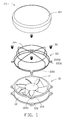
FIG. 1 is an isometric, exploded view of a fan assembly in accordance with a preferred embodiment of the present invention; and
FIG. 2 is an assembled view of FIG. 1.
DETAILED DESCRIPTION OF THE INVENTION
Referring to FIGS. 1-2, a fan assembly in accordance with a preferred embodiment of the present invention is illustrated. The fan assembly has a fan 10 and a fan guard 20 mounted on the fan 10 to protect the fan 10 from contamination of dust and damage during operation.
The fan 10 comprises a circular hollow body 12 and a motor 14 received in the body 12. The body 12 forms four pairs of triangle ears extending outwardly from a circumferential sidewall thereof. Each pair of the ears comprises a lower ear 122 and an upper ear 124 spaced from and opposite to the lower ear 122. A threaded hole 1200 is defined in each ear 122, 124 and the threaded holes 1200 of the upper ears 124 are provided for threadedly engaging with screws 30.
The fan guard 20 has a frame 22 and a hood 24 covering on the frame 22 and supported by the frame 22. The frame 22 is made of metal wires and comprises three annular ribs 220 and two pairs of supporters 224 interconnecting the annular ribs 220 together. The annular ribs 220 are concentrically disposed along an axial direction of the frame 22 and spaced apart with predetermined spacing. The three annular ribs 220 comprise a lower, a middle and an upper annular ribs 220 along a bottom-top direction of the frame 22. The lower annular rib 220 forms four annular fastening feet 2200 extending outwardly from a circumference thereof. Each fastening foot 2200 defines a through hole 2202 therein for extension of the screw 30. The fastening feet 2200 are integrally formed with the lower annular rib 220 by bending the lower annular rib 220. The lower annular rib 220 has a diameter similar to an outer diameter of the body 12 of the fan 10 to thereby facilitate positioning the frame 22 of the fan guard 20 on a top portion of the body 12 of the fan 10. The middle annular rib 220 has a largest diameter and the upper annular rib 220 has a smallest diameter, thereby forming an outwardly convex periphery when the hood 24 is mounted to the frame 22, to provide a larger space for airflow produced by the fan 10 passing through the fan guard 20 and entering the fan 10. The middle annular rib 220 is located adjacent to the lower annular rib 220 and distant from the upper annular rib 220.
The two pairs of supporters 224 are intercrossed at a top apex of the frame 22 of the fan guard 20. Each pair of the supporters 224 is attached to the three annular ribs 220 and connecting the three annular ribs 220 together. The two pairs of the supporters 224 are evenly distributed along a circumference of the frame 22 of the fan guard 20, thereby reinforcing stability of the frame 22, when the hood 24 is brought to spread over the frame 22, enclose the frame 22 and supported by the frame 22 to achieve an assembly of the frame 22 and the hood 24. The hood 24 encloses a top and a periphery of the frame 22.
The hood 24 of the fan guard 20 is made of one of gauze and netting, whereby the fan guard 20 can prevent the fan from contamination of dust and damage during operation. The hood 24 is brought to cover the frame 22 along the top-to-bottom direction of the frame 22 until a bottom of the hood 24 resiliently engage with the lower annular rib 220 of the frame 22, and whereby the hood 24 is supported by the frame 22 and cooperates with the frame 22 to form the fan guard 20 having a fixed shape for passing through of the airflow produced by the fan 10. Thus, the hood 24 of the fan guard 20, which is made of one of gauze or netting, can not only protect the fan 10 from contamination of dust and but also reduce noise produced by the fan 10.
In assembly, the screws 30 are brought to extend the through holes 2202 of the fastening feet 2200 of the lower annular rib 220 of the frame 22 and screwed into the threaded holes 1200 of the upper ears 124 of the top portion of the body 12 of the fan 10, thereby firmly securing the fan guard 20 to the top portion of the body 12 of the fan 10. The fan guard 20 is then placed on an air intake of the fan 10 at the top portion of the body 12 of the fan 10.
In use, the airflow produced by the fan 10 passes through the fan guard 20 towards the fan 10, whereby the fan guard 20 installed on the top portion of the body 12 of the fan 10 protects the motor 14 of the fan 10 from contamination of dust and damage during operation.
It is believed that the present embodiments and their advantages will be understood from the foregoing description, and it will be apparent that various changes may be made thereto without departing from the spirit and scope of the invention or sacrificing all of its material advantages, the examples hereinbefore described merely being preferred or exemplary embodiments of the invention.

Claims (14)

1. A fan assembly comprising:
a fan comprising a plurality of ears; and
a fan guard mounted on the fan, the fan guard comprising a frame and a hood covering on the frame and supported by the frame, the frame comprising a plurality of annular ribs and a plurality of supporters connecting the annular ribs together, the annular ribs being concentrically disposed along an axial direction of the fan guard and spaced apart with predetermined spacing;
wherein a lower annular rib comprises a plurality of fastening feet extending from a circumference thereof and wherein the fan guard is secured to the fan by fasteners extending through the fastening feet and engaging in the ears of the fan.
2. The fan assembly as claimed in claim 1, wherein the hood is made of one of gauze and netting and the frame is made of metal wires.
3. The fan assembly as claimed in claim 2, wherein the annular ribs comprise a middle annular rib has a diameter larger than that of any of the other annular ribs.
4. The fan assembly as claimed in claim 1, wherein the fan comprises a plurality of ears extending outwardly from a circumference thereof, the fasteners being extended through the fastening feet of the frame of the fan guard and screwed into the ears of the fan.
5. The fan assembly as claimed in claim 4, wherein the fan comprises a body and a motor received in the body, the ears being extended outwardly from a circumference of the body of the fan.
6. The fan assembly as claimed in claim 5, wherein the lower annular rib of the frame of the fan guard is positioned on a top portion of the body of the fan with the fastening feet of the frame of the fan guard corresponding to the ears of the body of the fan.
7. The fan assembly as claimed in claim 1, wherein the supporters are distributed along a circumference of the frame.
8. The fan assembly as claimed in claim 7, wherein the supporters are intercrossed at a top apex of the frame of the fan guard.
9. A fan assembly comprising:
a fan for generating an airflow and comprising a plurality of radailly extended ears; and
a fan guard mounted on the fan, the fan guard comprising a frame and a hood made of net, mounted over the frame and enclosing top and periphery of the frame, the frame comprising a plurality of concentrically arranged annular ribs spaced from each along an axial direction and a plurality of supporters connecting the annular ribs together;
wherein a lowest one of the annular ribs comprises a plurality of fastening feet extending from a circumference thereof and corresponding to the ears of the fan and wherein the fan guard is secured to the fan by fasteners extending through the fastening feet and engaging in the ears of the fan.
10. The fan assembly of claim 9, wherein the annular ribs and the supporters are made of metal wires.
11. The fan assembly of claim 10, wherein the hood has an outwardly convex periphery.
12. The fan assembly of claim 11, where one of the annular ribs located near the lowest one of the annular ribs has a diameter which is larger than any of others of the annular ribs.
13. The fan assembly of claim 11, wherein the fastening feet are formed by bending the lowest one of the annular ribs.
14. A fan assembly comprising:
a fan comprising a plurality of ears; and
a fan guard mounted on the fan, the fan guard comprising a frame and a hood made of one of gauze and netting, covering on the frame and supported by the frame, the frame comprising a plurality of annular ribs and a plurality of supporters connecting the annular ribs together, the annular ribs being concentrically disposed along an axial direction of the fan guard and spaced apart with predetermined spacing;
wherein a lower annular rib comprises a plurality of fastening feet extending from a circumference thereof and wherein the fan guard is secured to the fan by fasteners extending through the fastening feet and engaging in the ears of the fan.
US12/241,056 2008-06-19 2008-09-30 Fan assembly Expired - Fee Related US8087882B2 (en)

Applications Claiming Priority (3)

Application Number Priority Date Filing Date Title
CN200810302222 2008-06-19
CN200810302222.3 2008-06-19
CNA2008103022223A CN101608634A (en) 2008-06-19 2008-06-19 Combination of fans

Publications (2)

Publication Number Publication Date
US20090317239A1 US20090317239A1 (en) 2009-12-24
US8087882B2 true US8087882B2 (en) 2012-01-03

Family

ID=41431482

Family Applications (1)

Application Number Title Priority Date Filing Date
US12/241,056 Expired - Fee Related US8087882B2 (en) 2008-06-19 2008-09-30 Fan assembly

Country Status (2)

Country Link
US (1) US8087882B2 (en)
CN (1) CN101608634A (en)

Cited By (1)

* Cited by examiner, † Cited by third party
Publication number Priority date Publication date Assignee Title
US11242868B2 (en) * 2018-04-17 2022-02-08 Zhongshan Yibisi Technology Co., Ltd. Axial fan

Families Citing this family (4)

* Cited by examiner, † Cited by third party
Publication number Priority date Publication date Assignee Title
JP4323489B2 (en) * 2005-11-01 2009-09-02 ダイキン工業株式会社 Air conditioner outdoor unit
US9551498B2 (en) * 2012-06-28 2017-01-24 Samsung Electronics Co., Ltd. Indoor unit of air conditioner and method of controlling the air conditioner
US9829012B2 (en) 2013-11-22 2017-11-28 Lennox Industries Inc. Ice deflector for a fan housing
CN109340950A (en) * 2018-11-21 2019-02-15 珠海格力电器股份有限公司 A kind of air inlet mesh enclosure and air purifier

Citations (2)

* Cited by examiner, † Cited by third party
Publication number Priority date Publication date Assignee Title
CN2661968Y (en) 2003-12-05 2004-12-08 刘慧彬 Dust cover for fan
US7654309B2 (en) * 2005-09-12 2010-02-02 Fu Zhun Precision Industry (Shen Zhen) Co., Ltd. Heat dissipation device

Patent Citations (2)

* Cited by examiner, † Cited by third party
Publication number Priority date Publication date Assignee Title
CN2661968Y (en) 2003-12-05 2004-12-08 刘慧彬 Dust cover for fan
US7654309B2 (en) * 2005-09-12 2010-02-02 Fu Zhun Precision Industry (Shen Zhen) Co., Ltd. Heat dissipation device

Cited By (1)

* Cited by examiner, † Cited by third party
Publication number Priority date Publication date Assignee Title
US11242868B2 (en) * 2018-04-17 2022-02-08 Zhongshan Yibisi Technology Co., Ltd. Axial fan

Also Published As

Publication number Publication date
CN101608634A (en) 2009-12-23
US20090317239A1 (en) 2009-12-24

Similar Documents

Publication Publication Date Title
US8087882B2 (en) Fan assembly
US7654309B2 (en) Heat dissipation device
US7261516B2 (en) Fan holder assembly
US8267158B2 (en) Thermal module
US7416387B2 (en) Fan and fan frame thereof
US20060171802A1 (en) Centrifugal fan impeller
TWI553231B (en) Fan device and electronic device
US20140099197A1 (en) Centrifugal fan with ancillary airflow opening
US20130121816A1 (en) Blower with multiple air outlets
US11506223B2 (en) Fan design with an impact absorbing structure
US8987960B2 (en) Supporting and heat dissipating structure for motor having integrated driver
US20220074430A1 (en) Fan frame
US20090180877A1 (en) Fan device
US7731479B2 (en) Fan and fan housing with airflow-guiding stationary blades
MY183556A (en) Protective shield for an air discharge port of an air conditioner outdoor unit
TW201417691A (en) Air duct and heat dissipating system having the same
CN101614223B (en) Fan assembly
KR200477593Y1 (en) The ventilator
US20040076514A1 (en) Suspension type heat-dissipation fan
JP6008531B2 (en) Exhaust fan with protective guard for exhaust fan and protective guard for exhaust fan
US20080223554A1 (en) Fan
TWI438341B (en) Fan assembly
US9115723B2 (en) Cooling fan with impeller
JP2015218661A (en) Air blower
US1417470A (en) Fan for sewing machines

Legal Events

Date Code Title Description
AS Assignment

Owner name: HONG FU JIN PRECISION INDUSTRY (SHENZHEN) CO., LTD

Free format text: ASSIGNMENT OF ASSIGNORS INTEREST;ASSIGNOR:XU, HONG-BO;REEL/FRAME:021604/0146

Effective date: 20080825

Owner name: HON HAI PRECISION INDUSTRY CO., LTD., TAIWAN

Free format text: ASSIGNMENT OF ASSIGNORS INTEREST;ASSIGNOR:XU, HONG-BO;REEL/FRAME:021604/0146

Effective date: 20080825

REMI Maintenance fee reminder mailed
LAPS Lapse for failure to pay maintenance fees
STCH Information on status: patent discontinuation

Free format text: PATENT EXPIRED DUE TO NONPAYMENT OF MAINTENANCE FEES UNDER 37 CFR 1.362

FP Expired due to failure to pay maintenance fee

Effective date: 20160103