US8082375B2 - Noise-tolerant data communication system - Google Patents
Noise-tolerant data communication system Download PDFInfo
- Publication number
- US8082375B2 US8082375B2 US12/186,149 US18614908A US8082375B2 US 8082375 B2 US8082375 B2 US 8082375B2 US 18614908 A US18614908 A US 18614908A US 8082375 B2 US8082375 B2 US 8082375B2
- Authority
- US
- United States
- Prior art keywords
- data
- level
- data line
- signal
- line
- Prior art date
- Legal status (The legal status is an assumption and is not a legal conclusion. Google has not performed a legal analysis and makes no representation as to the accuracy of the status listed.)
- Active, expires
Links
Images


Classifications
-
- G—PHYSICS
- G06—COMPUTING OR CALCULATING; COUNTING
- G06F—ELECTRIC DIGITAL DATA PROCESSING
- G06F13/00—Interconnection of, or transfer of information or other signals between, memories, input/output devices or central processing units
- G06F13/10—Program control for peripheral devices
-
- G—PHYSICS
- G06—COMPUTING OR CALCULATING; COUNTING
- G06F—ELECTRIC DIGITAL DATA PROCESSING
- G06F1/00—Details not covered by groups G06F3/00 - G06F13/00 and G06F21/00
- G06F1/04—Generating or distributing clock signals or signals derived directly therefrom
- G06F1/12—Synchronisation of different clock signals provided by a plurality of clock generators
-
- G—PHYSICS
- G06—COMPUTING OR CALCULATING; COUNTING
- G06F—ELECTRIC DIGITAL DATA PROCESSING
- G06F13/00—Interconnection of, or transfer of information or other signals between, memories, input/output devices or central processing units
- G06F13/38—Information transfer, e.g. on bus
-
- G—PHYSICS
- G06—COMPUTING OR CALCULATING; COUNTING
- G06F—ELECTRIC DIGITAL DATA PROCESSING
- G06F13/00—Interconnection of, or transfer of information or other signals between, memories, input/output devices or central processing units
- G06F13/38—Information transfer, e.g. on bus
- G06F13/42—Bus transfer protocol, e.g. handshake; Synchronisation
- G06F13/4282—Bus transfer protocol, e.g. handshake; Synchronisation on a serial bus, e.g. I2C bus, SPI bus
- G06F13/4291—Bus transfer protocol, e.g. handshake; Synchronisation on a serial bus, e.g. I2C bus, SPI bus using a clocked protocol
Definitions
- This invention relates to a data communication system to perform data communication between a host and a device.
- FIG. 26 shows a structure of a conventional data communication system for a car audio.
- data communication between a microcomputer 100 and each of four ICs is performed through four communication lines, that are a control line (CE) 111 , a clock line (CL) 112 , a data input line (DI) 113 and a data output line (DO) 114 .
- the control line 111 provides a control signal CE and the clock line 112 provides a clock CL.
- the data input line 113 is used to input the data into the ICs, while the data output line 114 is used to output the data from the ICs.
- the four ICs are a display driver IC 115 , a key scan IC 116 , a DSP (Digital Signal Processor) 117 and an RDS/DARC (Radio Data System/Data Radio Channel) 118 . Between the key scan IC 116 and the microcomputer 100 , in particular, serial data communication is performed through the four lines described above.
- DSP Digital Signal Processor
- RDS/DARC Radio Data System/Data Radio Channel
- This kind of data communication system has been adopted in a very large number of electronic equipment, since it enables detecting a data read-in request signal (a signal to request reading-in of key data stored in the key scan IC 116 , for example) using the data output line 114 , that is, transmitting the data read-in request signal to the microcomputer 100 , as well as realizing very simple data communication.
- a data read-in request signal a signal to request reading-in of key data stored in the key scan IC 116 , for example
- a function of the data read-in request signal may be removed, or a terminal dedicated to output the data read-in request signal may be provided.
- enabling both the data transmission/reception function and the detection of the data read-in request signal eventually requires four communication lines which are not preferable in the case where there is the limitation on the number of communication lines as described above.
- the invention provides a data communication system that includes a host, a device, a control line connecting the host and the device so as to convey a control signal, a clock line connecting the host and the device so as to convey a clock, and a data line connecting the host and the device so as to convey data.
- the data line receives a data read-in request signal from the device and sends the data read-in request signal to the host when the control signal is at a first level.
- the data read-in request signal requests reading-in of the data by the host.
- the system includes a data line control circuit controlling the data line so that outputting of the data read-in request signal to the data line is disabled when first command data is inputted from the host to the device through the data line in synchronization with the clock and that the outputting of the data read-in request signal to the data line is enabled when second command data is inputted from the host to the device through the data line in synchronization with the clock.
- the system includes a data line control circuit controlling the data line so that outputting of the data read-in request signal to the data line is disabled when command data is inputted from the host to the device through the data line in synchronization with the clock and that the outputting of the data read-in request signal to the data line is enabled when the data is outputted from the device to the data line in synchronization with the clock.
- the system includes a data line control circuit controlling the data line so that outputting of the data read-in request signal to the data line is disabled when command data from the host is inputted to the device through the data line in synchronization with the clock and that the outputting of the data read-in request signal to the data line is enabled when the data is inputted from the host to the device through the data line in synchronization with the clock.
- FIG. 1 shows a structure of a data communication system according to a first embodiment of this invention.
- FIG. 2 shows a structure of the data communication system according to the first embodiment of this invention between a microcomputer and a key scan IC.
- FIG. 3 shows a structure of an interface in the data communication system according to the first embodiment of this invention.
- FIG. 4 shows a structure of a serial data input register.
- FIG. 5 shows a structure of a serial data output register.
- FIG. 6 shows a structure of a data line control circuit in the data communication system according to the first embodiment of this invention.
- FIGS. 7A-7D are timing charts showing operation of the data communication system according to the first embodiment of this invention.
- FIG. 8 shows a structure of a data communication system according to a second embodiment of this invention between a microcomputer and a key scan IC.
- FIG. 9 shows a structure of a data line control circuit in the data communication system according to the second embodiment of this invention.
- FIGS. 10A-10D are timing charts showing operation of the data communication system according to the second embodiment of this invention.
- FIG. 11 shows a structure of a data communication system according to a third embodiment of this invention between a microcomputer and a key scan IC.
- FIG. 12 shows a structure of a data line control circuit in the data communication system according to the third embodiment of this invention.
- FIGS. 13A-13D are timing charts showing operation of the data communication system according to the third embodiment of this invention.
- FIG. 14 shows a structure of a data communication system according to a fourth embodiment of this invention between a microcomputer and a key scan IC.
- FIG. 15 shows a structure of a data line control circuit in the data communication system according to the fourth embodiment of this invention.
- FIGS. 16A-16D are timing charts showing operation of the data communication system according to the fourth embodiment of this invention.
- FIG. 17 shows a structure of a data communication system according to a fifth embodiment of this invention between a microcomputer and a key scan IC.
- FIG. 18 shows a structure of a data line control circuit in the data communication system according to the fifth embodiment of this invention.
- FIG. 19 shows a structure of a data communication system according to a sixth embodiment of this invention between a microcomputer and a key scan IC.
- FIG. 20 shows a structure of a data line control circuit in the data communication system according to the sixth embodiment of this invention.
- FIG. 21 shows a structure of a data communication system according to a seventh embodiment of this invention between a microcomputer and a key scan IC.
- FIG. 22 shows a structure of a data line control circuit in the data communication system according to the seventh embodiment of this invention.
- FIG. 23 shows a structure of a data communication system according to an eighth embodiment of this invention between a microcomputer and a key scan IC.
- FIG. 24 shows a structure of a data line control circuit in the data communication system according to the eighth embodiment of this invention.
- FIG. 25 shows a structure of terminals in a data communication system.
- FIG. 26 shows a structure of a conventional data communication system.
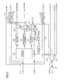
- FIG. 1 shows a structure of the data communication system for a car audio.
- data communication is performed among a microcomputer 10 (an example of “host” in this invention) and four ICs (examples of “devices” in this invention) through three lines, which are a control line (CE) 11 , a clock line (CL) 12 and a data line (DIO) 13 .
- a control signal CE is provided through the control line 11
- a clock CL is provided through the clock line 12
- data is inputted and outputted through the data line 13 .
- the data line 13 is connected to a power supply electric potential Vdd through a pull-up resistor Rpu that has a high resistance.
- the four ICs are a display driver IC 14 , a key scan IC 15 , a DSP 16 and an RDS/DARC (Radio Data System/Data Radio Channel) 17 .
- Data communication including inputting and outputting the data is performed between the key scan IC 15 and the microcomputer 10 through the three lines described above.
- FIG. 2 shows a structure of the data communication system between the microcomputer 10 and the key scan IC 15 .
- An interface 20 is provided inside the key scan IC 15 and controls transmission and reception of the data to and from the microcomputer 10 .
- the data outputted from the microcomputer 10 to the data line 13 is received by the interface 20 and stored into a serial data input register 21 .
- a key matrix 23 that is composed of a plurality of keys KY arrayed in a matrix form is provided outside the key scan IC 15 for a “person” to operate the audio equipment.
- a key scan circuit 24 detects turning ON/OFF of the keys in the key matrix 23 by key scan signals KS 1 -KS 6 and KI 1 -KI 4 , and outputs key data KD 0 -KD 23 that are results of the detection.
- the key data KD 0 -KD 23 are 24 bits of data since the key matrix 23 is formed of a matrix of four rows by six columns in this example.
- the serial data D 0 -D 5 stored in the control register 22 are used to control an operational state of the key scan circuit 24 .
- the key data KD 0 -KD 23 outputted from the key scan circuit 24 are stored into a serial data output register 25 , and a key data read-in request signal RDRQ is outputted from the serial output register 25 at the same time.
- the key data KD 0 -KD 23 stored in the serial data output register 25 and the key data read-in request signal RDRQ outputted from the serial data output register 25 are outputted to the data line 13 through the interface 20 , and are detected by and read into the microcomputer 10 . That is, the serial data output register 25 has a function to output the key data read-in request signal RDRQ to the microcomputer 10 as well as a function to transmit the key data KD 0 -KD 23 to the microcomputer 10 .
- a data line control circuit 26 that outputs a data line control signal DCMCNT to control functions (a function to transmit/receive the data and a function to detect the key data read-in request signal RDRQ) of the data line 13 that connects the microcomputer 10 and the key scan IC 15 .
- An address register 201 takes in various kinds of addresses transmitted from the microcomputer 10 through the data line 13 in synchronization with the clock CL.
- the addresses, the serial data and command data are inputted through a data input terminal DI that is connected to the data line 13 .
- a first address decoder 202 compares an address for inputting the command data taken into the address register 201 with an address for inputting the command data, which is pre-assigned to the key scan IC 15 , and outputs a signal of an H (high) level only when the addresses coincide with each other.
- a second address decoder 203 compares an address for inputting the serial data taken into the address register 201 with an address for inputting the serial data, which is pre-assigned to the key scan IC 15 , and outputs a signal of the H level only when the addresses coincide with each other.
- a third address decoder 204 compares an address for outputting the serial data taken into the address register 201 with an address for outputting the serial data, which is pre-assigned to the key scan IC 15 , and outputs a signal of the H level only when the addresses coincide with each other.
- a rise/fall detection circuit 205 detects a rise and a fall of the control signal CE, and is configured to generate a set signal ADSET that is a clock pulse of the H level when the control signal CE rises to the H level, and generates a reset signal ADRST that is a clock pulse of an L (low) level when the control signal CE falls to the L level.
- a first flip-flop 206 takes in the output of the first address decoder 202 in response to the set signal ADSET and resets its output to the L level in response to the reset signal ADRST.
- the signal of the H level is stored in the first flip-flop 206 as a command data input enable signal SDINENA.
- a second flip-flop 207 takes in the output of the second address decoder 203 in response to the set signal ADSET and resets its output to the L level in response to the reset signal ADRST.
- the signal of the H level is stored in the second flip-flop 207 as a serial data input enable signal SDINENB.
- a third flip-flop 208 takes in the output of the third address decoder 204 in response to the set signal ADSET and resets its output to the L level in response to the reset signal ADRST.
- the output of the third address decoder 204 is at the H level, the signal of the H level is stored in the third flip-flop 208 as a serial data output enable signal SDOUTEN.
- a first clock transmission circuit 209 and an AND circuit 216 transmit the clock CL and the data inputted to the terminal DI, respectively, to the serial data input register 21 based on either the command data input enable signal SDINENA or the serial data input enable signal SDINENB. Also, a second clock transmission circuit 210 transmits the clock CL to the serial data output register 25 based on the serial data output enable signal SDOUTEN.
- the serial data and the key data read-in request signal RDRQ are outputted to a terminal DO that is connected to the data line 13 together with the terminal DI.
- the terminal DO is connected with a drain of an output transistor 211 that is formed of an N-channel type MOS transistor.
- a gate of the output transistor 211 is connected with an output control circuit 212 that controls turning on/off of the output transistor 211 .
- the key data read-in request signal RDRQ, the data line control signal DCMCNT from the data line control circuit 26 and a reverse signal of the control signal CE are inputted to an AND circuit 213 in the output control circuit 212 .
- serial data output enable signal SDOUTEN and an output signal SDOUT from the serial data output register 25 are inputted to an AND circuit 214 in the output control circuit 212 .
- Outputs of the two AND circuits 213 and 214 are inputted to an OR circuit 215 in the output control circuit 212 .
- An output of the OR circuit 215 is applied to the gate of the output transistor 211 . That is, outputting of the key data read-in request signal RDRQ is disabled when the data line control signal DCMCNT is at the L level, and is enabled when the data line control signal DCMCNT is at the H level. Also, outputting of the output signal SDOUT of the serial data output register 25 is enabled when the serial data output enable signal SDOUTEN is at the H level.
- a structure of the serial data input register 21 is shown in FIG. 4 , while a structure of the serial data output register 25 is shown in FIG. 5 .
- a structure of the data line control circuit 26 is shown in FIG. 6 .
- Upper eight bits D 8 -D 15 of the serial data stored in the serial data input register 21 are taken into the data line control circuit 26 .
- the eight bits D 8 -D 15 of the serial data correspond to the command data.
- a fall detection circuit 261 detects a fall of the command data input enable signal SDINENA to the L level and generates a signal SDACK that is a clock pulse of the H level.
- An AND circuit 262 detects first command data “00001111” and outputs a set signal SETDT of the H level.
- an AND circuit 263 detects second command data “11111111” and outputs a reset signal RSTDT of the H level.
- the signal SDACK and the set signal SETDT are inputted to an AND circuit 264 , while the signal SDACK and the reset signal RSTDT are inputted to an AND circuit 265 .
- the key data read-in request signal RDRQ is inputted to the interface 20 shown in FIG. 3 .
- the serial data output enable signal SDOUTEN is at the L level and the control signal CE is at the L level.
- the data line control signal DCMCNT is at the H level
- the gate of the output transistor 211 at the terminal DO is turned to the H level to turn the data line 13 to the L level.
- the address “00000000” for inputting the command data is inputted in synchronization with the clock CL while the control signal CE is at the L level, and the address “00000000” is taken into the address register 201 in the interface 20 .
- the first address decoder 202 Since the address “00000000” taken into the address register 201 is the address for inputting the command data, the first address decoder 202 detects the coincidence of the addresses and outputs the signal of the H level.
- the set signal ADSET (a clock pulse of the H level) is generated to store the signal of the H level outputted from the first address decoder 202 into the first flip-flop 206 as the command data input enable signal SDINENA.
- the output transistor 211 When the control signal CE is at the H level, the output transistor 211 is turned off to turn the terminal DO into a high impedance state and consequently to turn the data line 13 into a high impedance state as well. Therefore, the data transmission is enabled for a period during which the control signal CE is at the H level.
- the clock CL appears in a signal SCLIN that is an output signal of the first clock transmission circuit 209
- the first command data “00001111” appears in a signal SDIN that is an output signal of the AND circuit 216
- the first command data is inputted into the serial data input register 21 in synchronization with the clock CL.
- the control signal CE When all of the first command data “00001111” is taken into the serial data input register 21 , the control signal CE is turned from the H level to the L level to generate the reset signal ADRST (a clock pulse of the L level), which turns the command data input enable signal SDINENA from the H level to the L level to halt the data transfer to the serial data input register 21 . While the first command data “00001111” is stored into the D 8 -D 15 in the serial data input register 21 as described above, they are outputted to the data line control circuit 26 .
- the serial data output enable signal SDOUTEN is at the L level
- the control signal CE is at the L level
- the data line control signal DCMCNT is turned to the L level. Therefore, the ordinary data transmission/reception is made possible even when the key data read-in request signal RDRQ is at the H level, because the gate of the output transistor 211 at the terminal DO in the interface 20 becomes the L level to turn off the output transistor 211 and to make the electric potential on the data line 13 the H level (high impedance).
- an address A 0 -A 7 for inputting eight-bit serial data is serially inputted to the terminal DI through the data line 13 in synchronization with the clock CL while the control signal CE is at the L level, and the address A 0 -A 7 is taken into the address register 201 .
- the second address decoder 203 Since the address A 0 -A 7 taken into the address register 201 is the address for inputting the serial data in this case, the second address decoder 203 outputs a signal of the H level. After that, when the control signal CE turns from the L level to the H level, the set signal ADSET (a clock pulse of the H level) is generated to store the signal of the H level outputted from the second address decoder 203 into the second flip-flop 207 as the serial data input enable signal SDINENB.
- the set signal ADSET a clock pulse of the H level
- the control signal CE is turned from the H level to the L level to generate the reset signal ADRST which turns the serial data input enable signal SDINENB from the H level to the L level to halt the data transfer to the serial data input register 21 .
- an address B 0 -B 7 for outputting eight-bit serial data is serially inputted to the terminal DI through the data line 13 in synchronization with the clock CL while the control signal CE is at the L level, and the address B 0 -B 7 is taken into the address register 201 .
- the third address decoder 204 Since the address B 0 -B 7 taken into the address register 201 is the address for outputting the serial data, the third address decoder 204 outputs a signal of the H level. After that, when the control signal CE turns from the L level to the H level, the set signal ADSET is generated to store the signal of the H level outputted from the third address decoder 204 into the third flip-flop 208 as the serial data output enable signal SDOUTEN.
- the clock CL when the clock CL is inputted while the control signal CE is at the H level, the clock CL appears in a signal SCLOUT that is an output signal of the second clock transmission circuit 210 .
- the clock CL Inputting the clock CL into the serial data output register 25 causes the key data KD 0 -KD 23 to appear in the signal SDOUT which is the output signal of the serial data output register 25 .
- the key data KD 0 -KD 23 are outputted to the interface 20 in synchronization with the clock CL.
- the key data KD 0 -KD 23 are outputted to the interface 20 , the key data KD 0 -KD 23 are outputted through the terminal DO to the data line 13 , since the serial data output enable signal SDOUTEN and the control signal CE are at the H level.
- the control signal CE is turned from the H level to the L level to generate the reset signal ADRST which turns the serial data output enable signal SDOUTEN from the H level to the L level to halt outputting the data from the serial data output register 25 , while the key data read-in request signal RDRQ varies from the H level to the L level to turn off the output transistor 211 at the same time.
- the data line 13 turns to a high impedance state.
- the key scan circuit 24 is put into operation and subsequently the key data KD 0 -KD 23 are stored into the serial data output register 25 and the key data read-in request signal RDRQ is turned from the L level to the H level.
- the key data read-in request signal RDRQ of the H level is inputted to the interface 20 .
- the serial data output enable signal SDOUTEN is at the L level and the control signal CE is at the L level
- the data line 13 remains at the H level (high impedance) because the data line control signal DCMCNT remains at the L level which keeps the gate of the output transistor 211 at the L level to keep the output transistor 211 turned off.
- the address “00000000” for inputting the command data is inputted in synchronization with the clock CL while the control signal CE is at the L level, and the address “00000000” is taken into the address register 201 . Since the address “00000000” taken into the address register 201 is the address for inputting the command data, the first address decoder 202 outputs a signal of the H level.
- the set signal ADSET is generated to store the signal of the H level outputted from the first address decoder 202 into the first flip-flop 206 as the command data output enable signal SDINENA. Since the terminal DO is in the high impedance state when the control signal CE is at the H level, the data line 13 also keeps the high impedance state.
- the control signal CE is turned from the H level to the L level to generate the reset signal ADRST which turns the command data input enable signal SDINENA from the H level to the L level to halt the data transfer to the serial data input register 21 .
- the serial data output enable signal SDOUTEN is at the L level
- the control signal CE is at the L level
- both the data communication and the detection of the data read-in request signal can be performed with the three lines that are the control line 11 , the clock line 12 and the data line 13 .
- it is tolerant of the noise since switching the functions (a function to transmit and receive the data and a function to detect the key data read-in request) of the data line 13 is carried out by inputting operations of the first and second command data.
- FIG. 8 shows a structure of a data communication system according to a second embodiment of this invention between the microcomputer 10 and the key scan IC 15 .
- a difference from the data communication system according to the first embodiment is in that the serial data output enable signal SDOUTEN generated in the interface 20 to control the data transmission/reception to and from the microcomputer 10 is inputted to the data line control circuit 26 .
- FIG. 9 shows a structure of the data line control circuit 26 .
- the data line control circuit 26 is provided with a fall detection circuit 267 that detects a fall of the serial data output enable signal SDOUTEN. Also, there is provided a NOR circuit 268 to which an output signal SDOCK of the fall detection circuit 267 and an output signal of the AND circuit 265 are inputted.
- the function of the data line 13 is switched to output a data read-in request by resetting the RS flip-flop 266 to turn the data control signal DCMCNT to the H level when outputting the serial data is completed in the second embodiment.
- Other structures are the same as those in the first embodiment.
- serial output enable signal SDOUTEN When the serial output enable signal SDOUTEN is varied from the H level to the L level, there is generated a signal SDOCK (a pulse of the H level) in the data line control circuit 26 , which in turn generates the signal CMRST (a pulse of the L level) that changes the data line control signal DCMCNT from the L level to the H level.
- SDOCK a pulse of the H level
- CMRST a pulse of the L level
- the serial data output enable signal SDOUTEN is at the L level
- the control signal CE is at the L level
- the data line control signal DCMCNT is at the H level as results of the operations described above, it is made possible that the state of the key data read-in request signal RDRQ is outputted to the data line 13 through the terminal DO in the interface 20 .
- both the data communication and the detection of the data read-in request signal can be performed with the three lines that are the control line 11 , the clock line 12 and the data line 13 .
- it is tolerant of the noise since switching the functions (a function to transmit and receive the data and a function to detect the key data read-in request) of the data line 13 is carried out by inputting operation of the command data and outputting operation of the serial data.
- FIG. 11 shows a structure of a data communication system according to a third embodiment of this invention between the microcomputer 10 and the key scan IC 15 . Differences from the data communication system according to the first embodiment are in that the serial data input enable signal SDINENB is inputted to the data line control circuit 26 and in that the serial data D 6 and D 7 inputted to the serial data input register 21 are inputted to the data line control circuit 26 .
- FIG. 12 shows a structure of the data line control circuit 26 .
- the data line control circuit 26 is provided with a fall detection circuit 269 that detects a fall of the serial data input enable signal SDINENB. Also, there is provided an AND circuit 270 to which the serial data D 6 and D 7 are inputted. When both the serial data D 6 and D 7 are “1”, an output of the AND circuit 270 is at the H level. In addition, there are provided an AND circuit 271 to which an output signal RSTND of the AND circuit 270 and an output signal SDBCK of the fall detection circuit 269 are inputted and a NOR circuit 272 to which an output signal of the AND circuit 271 and an output signal of the AND circuit 265 are inputted.
- the data line 13 is switched into a state in which the data read-in request can be outputted by resetting the RS flip-flop 266 to turn the data control signal DCMCNT to the H level in the case where both the serial data D 6 and D 7 are “1” after inputting of the serial data is completed in the third embodiment.
- Other structures are the same as those in the first embodiment.
- the serial data input enable signal SDINENB turns from the H level to the L level, there is generated the signal SDBCK (a pulse of the H level) in the data line control circuit 26 . Because the signal RSTND is at the H level when both the serial data D 6 and D 7 are “1”, the reset signal CMRST (a pulse of the L level) is generated to reset the RS flip-flop 266 and to turn the data line control signal DCMCNT from the L level to the H level.
- the control signal CE is at the L level and the data line control signal DCMCNT is at the H level as results of the operations described above, it is made possible that the state of the key data read-in request signal RDRQ is outputted to the data line 13 through the terminal DO in the interface 20 .
- the data line 13 is turned to the L level because the key data read-in request signal RDRQ is at the H level.
- the data line 13 is turned to the H level (high impedance).
- Next operation is outputting the serial data.
- ordinary data transmission/reception can be not performed while the data line 13 is at the L level. Therefore, in order to establish the state in which the ordinary data transmission/reception can be performed, the first command data “00001111” is inputted by the same method as in the first embodiment.
- the serial data output enable signal SDOUTEN is at the L level
- the control signal CE is at the L level
- the data line control signal DCMCNT is at the L level.
- the serial data is outputted in the same way as in the first embodiment.
- the control signal CE is turned from the H level to the L level to generate the reset signal ADRST (a clock pulse of the L level), which turns the serial data output enable signal SDOUTEN from the H level to the L level to halt outputting of the data from the serial data output register 25 , while the key data read-in request signal RDRQ varies from the H level to the L level to turn the data line 13 to the H level (high impedance).
- the key scan circuit 24 is put into operation and subsequently the key data KD 0 -KD 23 are stored into the serial data output register 25 and the key data read-in request signal RDRQ is turned from the L level to the H level.
- the gate of the N-channel transistor at the terminal DO remains at the L level to keep the data line 13 at the H level (high impedance), because the key data read-in request signal RDRQ of the H level is inputted to the interface 20 , the serial data output enable signal SDOUTEN remains at the L level, the control signal CE remains at the L level and the data line control signal DCMCNT remains at the L level.
- both the data communication and the detection of the data read-in request signal can be performed with the three lines that are the control line 11 , the clock line 12 and the data line 13 .
- it is tolerant of the noise since switching the functions (a function to transmit and receive the data and a function to detect the key data read-in request) of the data line 13 is carried out by the inputting operation of the command data and the inputting operation of the serial data.
- FIG. 14 shows a structure of a data communication system according to a fourth embodiment of this invention between the microcomputer 10 and the key scan IC 15 .
- Differences from the data communication system according to the first embodiment are in that the serial data output enable signal SDOUTEN is inputted to the data line control circuit 26 and in that the serial data D 6 and D 7 outputted from the serial data input register 21 are inputted to the data line control circuit 26 .
- the data communication system according to the fourth embodiment is a combination of the data communication system according to the second embodiment and the data communication system according to the third embodiment.
- FIG. 15 shows a structure of the data line control circuit 26 .
- the circuit shown in FIG. 15 is a combination of the circuit shown in FIG. 9 and the circuit shown in FIG. 12 , and is provided with a NOR circuit 273 to which the output signal of the AND circuit 271 , the signal SDOCK and the output signal of the AND circuit 265 are inputted.
- the function of the data line 13 is switched to output the data read-in request by resetting the RS flip-flop 266 based on the values of the serial data D 6 and D 7 to turn the data control signal DCMCNT to the H level when the inputting operation of the serial data is completed in the fourth embodiment.
- the function of the data line 13 is switched to output the data read-in request by resetting the RS flip-flop 266 to turn the data control signal DCMCNT to the H level also when the outputting operation of the serial data is completed.
- FIGS. 16A-16D are timing charts showing operations of the data communication system according to the fourth embodiment of this invention. Explanations are omitted since the operations are a combination of the operations of the data communication system according to the second embodiment and the operations of the data communication system according to the third embodiment.
- FIG. 17 shows a structure of a data communication system according to a fifth embodiment of this invention between the microcomputer 10 and the key scan IC 15 .
- the data communication system according to the fifth embodiment is formed by adding a serial data counter 27 to the key scan IC 15 (Refer to FIG. 2 .) in the data communication system according to the first embodiment.
- the serial data counter 27 counts the number of bits of the data by counting the number of clocks CL appeared in the signal SCLIN that is inputted to the serial data input register 21 .
- the numbers of bits of the first command data “00001111” and the second command data “11111111” are counted when they are inputted to the serial data input register 21 , and the results are inputted to the data line control circuit 26 to increase accuracy in setting the data line control signal DCMCNT.
- FIG. 18 A structure of the data line control circuit 26 is shown in FIG. 18 . Similar to the circuit (Refer to FIG. 6 .) in the data communication system according to the first embodiment, the set signal SETDT and the signal SDACK are inputted to an AND circuit 264 A while the reset signal RSTDT and the signal SDACK are inputted to an AND circuit 265 A. An output signal BIT 8 of the serial data counter 27 is also inputted to each of the AND circuits 264 A and 265 A, respectively. When the number of bits counted by the serial data counter 27 reaches eight, the output signal BIT 8 turns to the H level to activate the AND circuits 264 A and 265 A, enabling set/reset operation of the RS flip-flop 266 . When the number of bits counted by the serial data counter 27 does not reach eight, on the other hand, the output signal BIT 8 is at the L level and the data line control circuit 26 is disabled.
- FIG. 19 shows a structure of a data communication system according to a sixth embodiment of this invention between the microcomputer 10 and the key scan IC 15 .
- the data communication system according to the sixth embodiment is formed by adding the serial data counter 27 to the key scan IC 15 (Refer to FIG. 8 .) in the data communication system according to the second embodiment.
- the serial data counter 27 counts the number of bits of the data by counting the number of clocks CL appeared in the signal SCLIN that is inputted to the serial data input register 21 .
- the numbers of bits of the first command data “00001111” and the second command data “11111111” are counted when they are inputted to the serial data input register 21 , and the results are inputted to the data line control circuit 26 to increase accuracy in setting the data line control signal DCMCNT.
- FIG. 20 A structure of the data line control circuit 26 is shown in FIG. 20 . Similar to the circuit (Refer to FIG. 9 .) in the data communication system according to the second embodiment, the set signal SETDT and the signal SDACK are inputted to the AND circuit 264 A while the reset signal RSTDT and the signal SDACK are inputted to the AND circuit 265 A.
- FIG. 21 shows a structure of a data communication system according to a seventh embodiment of this invention between the microcomputer 10 and the key scan IC 15 .
- the data communication system according to the seventh embodiment is formed by adding the serial data counter 27 to the key scan IC 15 (Refer to FIG. 11 .) in the data communication system according to the third embodiment.
- the serial data counter 27 counts the number of bits of the data by counting the number of clocks CL appeared in the signal SCLIN that is inputted to the serial data input register 21 .
- the numbers of bits of the first command data “00001111” and the second command data “11111111” are counted when they are inputted to the serial data input register 21 , and the results are inputted to the data line control circuit 26 to increase accuracy in setting the data line control signal DCMCNT.
- FIG. 22 A structure of the data line control circuit 26 is shown in FIG. 22 . Similar to the circuit (Refer to FIG. 12 .) in the data communication system according to the third embodiment, the set signal SETDT and the signal SDACK are inputted to the AND circuit 264 A while the reset signal RSTDT and the signal SDACK are inputted to the AND circuit 265 A.
- FIG. 23 shows a structure of a data communication system according to an eighth embodiment of this invention between the microcomputer 10 and the key scan IC 15 .
- the data communication system according to the eighth embodiment is formed by adding the serial data counter 27 to the key scan IC 15 (Refer to FIG. 14 .) in the data communication system according to the fourth embodiment.
- the serial data counter 27 counts the number of bits of the data by counting the number of clocks CL appeared in the signal SCLIN that is inputted to the serial data input register 21 .
- the numbers of bits of the first command data “00001111” and the second command data “11111111” are counted when they are inputted to the serial data input register 21 , and the results are inputted to the data line control circuit 26 to increase accuracy in setting the data line control signal DCMCNT.
- FIG. 24 A structure of the data line control circuit 26 is shown in FIG. 24 . Similar to the circuit (Refer to FIG. 15 .) in the data communication system according to the fourth embodiment, the set signal SETDT and the signal SDACK are inputted to the AND circuit 264 A while the reset signal RSTDT and the signal SDACK are inputted to the AND circuit 265 A.
- this invention is not limited to the embodiments described above and may be modified within the scope of the invention.
- the data communication systems according to the first through eighth embodiments are related to the data communication system for the car audio, this invention may be widely applied to other data communication systems between a host and a device using three lines.
- the data communication systems according to the first through eighth embodiments are provided with the terminal DI and the terminal DO as the external terminals of the key scan IC 15 , they may be provided with an external terminal DIO that is a combination of the terminal DI and the terminal DO connected together inside the IC (Refer to FIG. 25 .).
- both the data communication and the detection of the data read-in request signal can be performed with the three lines that are the control line, the clock line and the data line.
- they are tolerant of the noise since switching the functions (the function to transmit and receive the data and the function to detect the key data read-in request) of the data line is carried out by the inputting operation of the command data, by the inputting operation of the command data and the outputting operation of the serial data, or by the inputting operation of the command data and the inputting operation of the serial data.
Landscapes
- Engineering & Computer Science (AREA)
- Theoretical Computer Science (AREA)
- Physics & Mathematics (AREA)
- General Engineering & Computer Science (AREA)
- General Physics & Mathematics (AREA)
- Communication Control (AREA)
- Small-Scale Networks (AREA)
- Dc Digital Transmission (AREA)
- Information Transfer Systems (AREA)
Abstract
Description
Claims (20)
Applications Claiming Priority (2)
| Application Number | Priority Date | Filing Date | Title |
|---|---|---|---|
| JP2007-204082 | 2007-08-06 | ||
| JP2007204082A JP4931727B2 (en) | 2007-08-06 | 2007-08-06 | Data communication system |
Publications (2)
| Publication Number | Publication Date |
|---|---|
| US20090043929A1 US20090043929A1 (en) | 2009-02-12 |
| US8082375B2 true US8082375B2 (en) | 2011-12-20 |
Family
ID=40347548
Family Applications (1)
| Application Number | Title | Priority Date | Filing Date |
|---|---|---|---|
| US12/186,149 Active 2029-06-08 US8082375B2 (en) | 2007-08-06 | 2008-08-05 | Noise-tolerant data communication system |
Country Status (5)
| Country | Link |
|---|---|
| US (1) | US8082375B2 (en) |
| JP (1) | JP4931727B2 (en) |
| KR (1) | KR101023280B1 (en) |
| CN (1) | CN101364922B (en) |
| TW (1) | TWI398778B (en) |
Families Citing this family (1)
| Publication number | Priority date | Publication date | Assignee | Title |
|---|---|---|---|---|
| KR101319903B1 (en) | 2009-09-21 | 2013-10-18 | 엘지전자 주식회사 | Method for transmitting sounding reference signal in wireless communication system and apparatus therefor |
Citations (6)
| Publication number | Priority date | Publication date | Assignee | Title |
|---|---|---|---|---|
| JPH09238150A (en) | 1996-02-29 | 1997-09-09 | Sanyo Electric Co Ltd | Data transfer system |
| JPH09238151A (en) | 1996-02-29 | 1997-09-09 | Sanyo Electric Co Ltd | Data transfer system |
| US20020054684A1 (en) * | 1999-01-11 | 2002-05-09 | Menzl Stefan Daniel | Process for digital communication and system communicating digitally |
| US20020105842A1 (en) * | 1999-11-22 | 2002-08-08 | Fujitsu Limited | Semiconductor memory device having improved data transfer rate without providing a register for holding write data |
| US20050245218A1 (en) * | 2000-06-06 | 2005-11-03 | Conexant Systems, Inc. | System and method of frequency synthesis to avoid gaps and VCO pulling in direct broadcast statelite systems |
| US20060277426A1 (en) * | 2005-04-27 | 2006-12-07 | Markus Lindorfer | Memory device, use thereof and method for synchronizing a data word |
Family Cites Families (2)
| Publication number | Priority date | Publication date | Assignee | Title |
|---|---|---|---|---|
| JP3920830B2 (en) * | 2003-09-19 | 2007-05-30 | 三洋電機株式会社 | Interface circuit, data processing circuit, data processing system, integrated circuit |
| US20060031618A1 (en) * | 2004-05-20 | 2006-02-09 | Hansquine David W | Single wire and three wire bus interoperability |
-
2007
- 2007-08-06 JP JP2007204082A patent/JP4931727B2/en not_active Expired - Fee Related
-
2008
- 2008-04-11 TW TW097113144A patent/TWI398778B/en not_active IP Right Cessation
- 2008-08-04 CN CN2008101451671A patent/CN101364922B/en not_active Expired - Fee Related
- 2008-08-05 KR KR1020080076417A patent/KR101023280B1/en not_active Expired - Fee Related
- 2008-08-05 US US12/186,149 patent/US8082375B2/en active Active
Patent Citations (6)
| Publication number | Priority date | Publication date | Assignee | Title |
|---|---|---|---|---|
| JPH09238150A (en) | 1996-02-29 | 1997-09-09 | Sanyo Electric Co Ltd | Data transfer system |
| JPH09238151A (en) | 1996-02-29 | 1997-09-09 | Sanyo Electric Co Ltd | Data transfer system |
| US20020054684A1 (en) * | 1999-01-11 | 2002-05-09 | Menzl Stefan Daniel | Process for digital communication and system communicating digitally |
| US20020105842A1 (en) * | 1999-11-22 | 2002-08-08 | Fujitsu Limited | Semiconductor memory device having improved data transfer rate without providing a register for holding write data |
| US20050245218A1 (en) * | 2000-06-06 | 2005-11-03 | Conexant Systems, Inc. | System and method of frequency synthesis to avoid gaps and VCO pulling in direct broadcast statelite systems |
| US20060277426A1 (en) * | 2005-04-27 | 2006-12-07 | Markus Lindorfer | Memory device, use thereof and method for synchronizing a data word |
Also Published As
| Publication number | Publication date |
|---|---|
| CN101364922A (en) | 2009-02-11 |
| US20090043929A1 (en) | 2009-02-12 |
| KR20090014976A (en) | 2009-02-11 |
| TWI398778B (en) | 2013-06-11 |
| KR101023280B1 (en) | 2011-03-18 |
| TW200907691A (en) | 2009-02-16 |
| JP2009044219A (en) | 2009-02-26 |
| JP4931727B2 (en) | 2012-05-16 |
| CN101364922B (en) | 2012-08-15 |
Similar Documents
| Publication | Publication Date | Title |
|---|---|---|
| US6690191B2 (en) | Bi-directional output buffer | |
| KR101329850B1 (en) | Semiconductor device and data processing system | |
| US20020108011A1 (en) | Dual interface serial bus | |
| US12323275B2 (en) | Transmission device and communication system | |
| US8948209B2 (en) | Transmission over an 12C bus | |
| EP2115606B1 (en) | Integrated circuit and electronic device | |
| US8082375B2 (en) | Noise-tolerant data communication system | |
| US7888962B1 (en) | Impedance matching circuit | |
| JP2005234976A (en) | Storage device | |
| US10637471B1 (en) | Termination circuit and semiconductor apparatus including the termination circuit | |
| US20170302276A1 (en) | Impedance calibration circuit and semiconductor memory apparatus having the same | |
| JPH11154859A (en) | Multi-level signal transmission method, multi-level signal transmission system, and semiconductor integrated circuit | |
| US20060059280A1 (en) | Digital programming interface between a baseband processor and an integrated radio-frequency module | |
| US8006012B2 (en) | Data storage system | |
| JP2016224588A (en) | Controller and control method | |
| US12040794B2 (en) | Semiconductor integrated circuits that support enhanced signal multiplexing operations for I/O buffers | |
| US20040141520A1 (en) | Device for controlling decoder extension cards and universal extension cards | |
| KR100207482B1 (en) | Smart card parity detection device | |
| JPH06124257A (en) | Serial I / O control circuit | |
| JP2007226748A (en) | Control bus data receiving circuit and bus data detecting method using the same | |
| KR20050063203A (en) | Semiconductor memory device | |
| JP2000339063A (en) | Communication device | |
| JPH0353634A (en) | Integrated circuit for communication | |
| JP2007241911A (en) | USB transceiver |
Legal Events
| Date | Code | Title | Description |
|---|---|---|---|
| AS | Assignment |
Owner name: SANYO ELECTRIC CO., LTD., JAPAN Free format text: ASSIGNMENT OF ASSIGNORS INTEREST;ASSIGNORS:TOKUNAGA, TETSUYA;YAMAGATA, YOSHIYUKI;OSAWA, YASUO;AND OTHERS;REEL/FRAME:021687/0128 Effective date: 20080911 Owner name: SANYO SEMICONDUCTOR CO., LTD., JAPAN Free format text: ASSIGNMENT OF ASSIGNORS INTEREST;ASSIGNORS:TOKUNAGA, TETSUYA;YAMAGATA, YOSHIYUKI;OSAWA, YASUO;AND OTHERS;REEL/FRAME:021687/0128 Effective date: 20080911 |
|
| AS | Assignment |
Owner name: SEMICONDUCTOR COMPONENTS INDUSTRIES, LLC, ARIZONA Free format text: ASSIGNMENT OF ASSIGNORS INTEREST;ASSIGNOR:SANYO ELECTRIC CO., LTD.;REEL/FRAME:026594/0385 Effective date: 20110101 |
|
| STCF | Information on status: patent grant |
Free format text: PATENTED CASE |
|
| FEPP | Fee payment procedure |
Free format text: PAYOR NUMBER ASSIGNED (ORIGINAL EVENT CODE: ASPN); ENTITY STATUS OF PATENT OWNER: LARGE ENTITY |
|
| AS | Assignment |
Owner name: SEMICONDUCTOR COMPONENTS INDUSTRIES, LLC, ARIZONA Free format text: CORRECTIVE ASSIGNMENT TO CORRECT THE INCORRECT #12/577882 PREVIOUSLY RECORDED ON REEL 026594 FRAME 0385. ASSIGNOR(S) HEREBY CONFIRMS THE ASSIGNMENT;ASSIGNOR:SANYO ELECTRIC CO., LTD;REEL/FRAME:032836/0342 Effective date: 20110101 |
|
| AS | Assignment |
Owner name: SEMICONDUCTOR COMPONENTS INDUSTRIES, LLC, ARIZONA Free format text: ASSIGNMENT OF ASSIGNORS INTEREST;ASSIGNOR:SANYO SEMICONDUCTOR CO., LTD.;REEL/FRAME:032891/0906 Effective date: 20140509 |
|
| FPAY | Fee payment |
Year of fee payment: 4 |
|
| AS | Assignment |
Owner name: SYSTEM SOLUTIONS CO., LTD., JAPAN Free format text: CHANGE OF NAME;ASSIGNOR:SANYO SEMICONDUCTOR CO., LTD.;REEL/FRAME:037773/0090 Effective date: 20140228 |
|
| AS | Assignment |
Owner name: SEMICONDUCTOR COMPONENTS INDUSTRIES, LLC, ARIZONA Free format text: CORRECTIVE ASSIGNMENT TO CORRECT THE ASSIGNOR NAME PREVIOUSLY RECORDED AT REEL: 032891 FRAME: 0906. ASSIGNOR(S) HEREBY CONFIRMS THE ASSIGNMENT;ASSIGNOR:SYSTEM SOLUTIONS CO., LTD.;REEL/FRAME:037881/0027 Effective date: 20140509 |
|
| AS | Assignment |
Owner name: DEUTSCHE BANK AG NEW YORK BRANCH, NEW YORK Free format text: SECURITY INTEREST;ASSIGNOR:SEMICONDUCTOR COMPONENTS INDUSTRIES, LLC;REEL/FRAME:038620/0087 Effective date: 20160415 |
|
| AS | Assignment |
Owner name: DEUTSCHE BANK AG NEW YORK BRANCH, AS COLLATERAL AG Free format text: CORRECTIVE ASSIGNMENT TO CORRECT THE INCORRECT PATENT NUMBER 5859768 AND TO RECITE COLLATERAL AGENT ROLE OF RECEIVING PARTY IN THE SECURITY INTEREST PREVIOUSLY RECORDED ON REEL 038620 FRAME 0087. ASSIGNOR(S) HEREBY CONFIRMS THE SECURITY INTEREST;ASSIGNOR:SEMICONDUCTOR COMPONENTS INDUSTRIES, LLC;REEL/FRAME:039853/0001 Effective date: 20160415 Owner name: DEUTSCHE BANK AG NEW YORK BRANCH, AS COLLATERAL AGENT, NEW YORK Free format text: CORRECTIVE ASSIGNMENT TO CORRECT THE INCORRECT PATENT NUMBER 5859768 AND TO RECITE COLLATERAL AGENT ROLE OF RECEIVING PARTY IN THE SECURITY INTEREST PREVIOUSLY RECORDED ON REEL 038620 FRAME 0087. ASSIGNOR(S) HEREBY CONFIRMS THE SECURITY INTEREST;ASSIGNOR:SEMICONDUCTOR COMPONENTS INDUSTRIES, LLC;REEL/FRAME:039853/0001 Effective date: 20160415 |
|
| MAFP | Maintenance fee payment |
Free format text: PAYMENT OF MAINTENANCE FEE, 8TH YEAR, LARGE ENTITY (ORIGINAL EVENT CODE: M1552); ENTITY STATUS OF PATENT OWNER: LARGE ENTITY Year of fee payment: 8 |
|
| MAFP | Maintenance fee payment |
Free format text: PAYMENT OF MAINTENANCE FEE, 12TH YEAR, LARGE ENTITY (ORIGINAL EVENT CODE: M1553); ENTITY STATUS OF PATENT OWNER: LARGE ENTITY Year of fee payment: 12 |
|
| AS | Assignment |
Owner name: FAIRCHILD SEMICONDUCTOR CORPORATION, ARIZONA Free format text: RELEASE OF SECURITY INTEREST IN PATENTS RECORDED AT REEL 038620, FRAME 0087;ASSIGNOR:DEUTSCHE BANK AG NEW YORK BRANCH, AS COLLATERAL AGENT;REEL/FRAME:064070/0001 Effective date: 20230622 Owner name: SEMICONDUCTOR COMPONENTS INDUSTRIES, LLC, ARIZONA Free format text: RELEASE OF SECURITY INTEREST IN PATENTS RECORDED AT REEL 038620, FRAME 0087;ASSIGNOR:DEUTSCHE BANK AG NEW YORK BRANCH, AS COLLATERAL AGENT;REEL/FRAME:064070/0001 Effective date: 20230622 |