US8081575B2 - System and method for dynamic adaptation of data rate and transmit power with a beaconing protocol - Google Patents
System and method for dynamic adaptation of data rate and transmit power with a beaconing protocol Download PDFInfo
- Publication number
- US8081575B2 US8081575B2 US11/577,537 US57753705A US8081575B2 US 8081575 B2 US8081575 B2 US 8081575B2 US 57753705 A US57753705 A US 57753705A US 8081575 B2 US8081575 B2 US 8081575B2
- Authority
- US
- United States
- Prior art keywords
- feedback
- beacon
- power
- data rate
- information element
- Prior art date
- Legal status (The legal status is an assumption and is not a legal conclusion. Google has not performed a legal analysis and makes no representation as to the accuracy of the status listed.)
- Active, expires
Links
Images


Classifications
-
- H—ELECTRICITY
- H04—ELECTRIC COMMUNICATION TECHNIQUE
- H04W—WIRELESS COMMUNICATION NETWORKS
- H04W52/00—Power management, e.g. TPC [Transmission Power Control], power saving or power classes
- H04W52/04—TPC
- H04W52/18—TPC being performed according to specific parameters
- H04W52/26—TPC being performed according to specific parameters using transmission rate or quality of service QoS [Quality of Service]
- H04W52/267—TPC being performed according to specific parameters using transmission rate or quality of service QoS [Quality of Service] taking into account the information rate
-
- H—ELECTRICITY
- H04—ELECTRIC COMMUNICATION TECHNIQUE
- H04W—WIRELESS COMMUNICATION NETWORKS
- H04W28/00—Network traffic management; Network resource management
- H04W28/16—Central resource management; Negotiation of resources or communication parameters, e.g. negotiating bandwidth or QoS [Quality of Service]
- H04W28/18—Negotiating wireless communication parameters
- H04W28/22—Negotiating communication rate
-
- H—ELECTRICITY
- H04—ELECTRIC COMMUNICATION TECHNIQUE
- H04W—WIRELESS COMMUNICATION NETWORKS
- H04W28/00—Network traffic management; Network resource management
- H04W28/16—Central resource management; Negotiation of resources or communication parameters, e.g. negotiating bandwidth or QoS [Quality of Service]
- H04W28/26—Resource reservation
-
- H—ELECTRICITY
- H04—ELECTRIC COMMUNICATION TECHNIQUE
- H04W—WIRELESS COMMUNICATION NETWORKS
- H04W52/00—Power management, e.g. TPC [Transmission Power Control], power saving or power classes
- H04W52/04—TPC
- H04W52/18—TPC being performed according to specific parameters
- H04W52/22—TPC being performed according to specific parameters taking into account previous information or commands
- H04W52/228—TPC being performed according to specific parameters taking into account previous information or commands using past power values or information
-
- H—ELECTRICITY
- H04—ELECTRIC COMMUNICATION TECHNIQUE
- H04W—WIRELESS COMMUNICATION NETWORKS
- H04W52/00—Power management, e.g. TPC [Transmission Power Control], power saving or power classes
- H04W52/04—TPC
- H04W52/18—TPC being performed according to specific parameters
- H04W52/24—TPC being performed according to specific parameters using SIR [Signal to Interference Ratio] or other wireless path parameters
-
- H—ELECTRICITY
- H04—ELECTRIC COMMUNICATION TECHNIQUE
- H04W—WIRELESS COMMUNICATION NETWORKS
- H04W52/00—Power management, e.g. TPC [Transmission Power Control], power saving or power classes
- H04W52/04—TPC
- H04W52/18—TPC being performed according to specific parameters
- H04W52/26—TPC being performed according to specific parameters using transmission rate or quality of service QoS [Quality of Service]
-
- H—ELECTRICITY
- H04—ELECTRIC COMMUNICATION TECHNIQUE
- H04W—WIRELESS COMMUNICATION NETWORKS
- H04W52/00—Power management, e.g. TPC [Transmission Power Control], power saving or power classes
- H04W52/04—TPC
- H04W52/54—Signalisation aspects of the TPC commands, e.g. frame structure
Definitions
- the present invention relates to a protocol for ultra wide-band (UWB) medium access control (MAC). More particularly, the present invention relates to an enhanced protocol for UWB MAC. Also the present invention relates to an enhanced protocol for UWB MAC comprising a distributed reservation protocol (DRP). The invention also relates to any wireless system that uses a MAC protocol, in which devices are sending a beacon.
- UWB ultra wide-band
- DRP distributed reservation protocol
- the invention also relates to any wireless system that uses a MAC protocol, in which devices are sending a beacon.
- Wireless personal area networks are intended for communication on short links of up to ten or several tens of meters and do not rely on an installed infrastructure in most cases. Nevertheless some existing WPANs like Bluetooth or IEEE 802.15.3 rely on a central unit like the “Piconet Coordinator”. This makes topology management quite complex in ad hoc scenarios, in which no infrastructure is available.
- a distributed MAC protocol eliminates the need for a network infrastructure by distributing functions across all devices, i.e., nodes.
- Asynchronous and isochronous data transfers are supported in most WPANs. Whereas in Bluetooth and IEEE 802.15.3 isochronous transfer is organized by the piconet coordinator, it is handled in a fully distributed manner in the present invention.
- MAC Wireless Medium Access Control
- beacon 105 provides the basic timing for the network and transmits information regarding isochronous reservations, sleep periods, etc. All devices announce their isochronous airtime utilization via beacon transmission, recognize neighboring devices' airtime utilization by receiving beacons from them, and respect other devices' airtime utilization prior to transmitting/receiving data.
- a very efficient real-time streaming protocol enables the controlled delivery of real-time data, such as audio and video.
- Sources of data can include both live data feeds, such as live audio and video, and stored content, such as pre-recorded events.
- time is divided into superframes 100 of length 65,536 [usec], which are composed of 256 Media Access Slots (MAS) where each MAS length is 256[usec].
- MAS slots are numbered from 0 to 255. Several slot types are defined depending on how the MAS are utilized by the device or devices nearby.
- beacon frames periodically send a beacon frame to announce their presence, medium reservations, sleep periods, etc.
- Beacons of one or several devices are grouped into one or several contiguous “beacon periods” (BP) 102 (in the latest version of the MBOA standard only a single beacon period per superframe).
- BP beacon period
- a device Before communication can be established, a device must create its own beacon period or join an existing beacon period.
- For each beacon period 102 a certain number of consecutive MAS slots are utilized as beacon slots, where all the devices transmit their beacons 105 .
- Each MAS comprises 3 beacon slots.
- the length of the BP is dynamic and adapts to the number of occupied beacon slots in the BP.
- the start time of a superframe 100 is determined by the beginning of a beacon period 101 and is defined as a beacon period start time (BPST) and MAS slots are numbered relative to this starting time.
- BPST beacon period start time
- MCS Modulation and Coding Scheme
- the present invention addresses the problem of appropriate MCS and transmit (TX) power selection on the transmitter side and provides a very powerful and efficient solution based on a beaconing concept.
- An adaptation of the MCS and/or TX power is frequently needed because of varying channel conditions in wireless systems (but also wired systems to a certain extent).
- a variation in the channel conditions can be due to interference from other devices in the same or different networks, channel fading e.g. due to terminal mobility, varying distance between sender and receiver, etc.
- the difficulty in the appropriate selection of MCS and TX power is that the channel conditions on the receiving side should determine the selection, as the receiver has to decode received data correctly.
- the sender is in general only aware of its own channel conditions but not the channel conditions on the receiver side. There are two basic approaches to this problem.
- the first approach is that the sender estimates the channel conditions on the receiver side. This estimate could, e.g., be based on the number of positive acknowledgements received from the receiver, rsp. the number of frames in error. It could also be based on the Received Signal Strength (RSS) of frames received from the receiver or the Signal to Noise Ratio (SNR) of such frames on the sender side, which presumes a certain channel reciprocity or at least correlation between the sender-to-receiver and receiver-to-sender direction.
- RSS Received Signal Strength
- SNR Signal to Noise Ratio
- the second type of approach is that the receiver sends explicit feedback to the sender regarding the channel conditions on the receiver side or that the receiver even recommends MCS and TX power. Such an approach is in general more accurate and faster than the estimation approach. On the other hand, the explicit feedback creates more overhead than the estimation approach.
- the present invention enables explicit feedback from the receiver while at the same time keeping the signalling overhead minimal. Accordingly, every device transmits a beacon frame, in which it includes feedback for ongoing transmissions, in which the device is a receiver.
- This feedback can be either incremental or full feedback on the MCS and TX power selection or just include channel information from the receiver side.
- Incremental feedback regarding MCS and TX power selection means that the receiver indicates in its beacon whether to increase or decrease (or keep unchanged) the data rate (rsp. MCS) and TX power. This increase or decrease is defined in steps. Upon receiving this indication the sender may follow this recommendation and increase/decrease/keep unchanged the MCS and/or TX power by one (or several) steps.
- the beacon includes separate recommendations for MCS and TX power. The sender may also apply some form of sliding average scheme and may follow receiver recommendations only with a certain delay.
- Full feedback regarding MCS and TX power selection means that the receiver includes in its beacon a specific recommendation which MCS and TX power the sender should use.
- each MCS may be designated by a code, rsp. combination of bits.
- the recommended TX power level may also signalled by means of a code (if the TX power is defined in steps) or as an absolute value.
- the sender may accept this recommendation and change the MCS and/or power to the recommended value.
- the channel information could, e.g., include the RSS or SNR of the packets received from the sender or the Packet Error Ratio (PER) or other related information.
- the sender Upon reception of channel information feedback, the sender chooses an appropriate MCS and TX power on its own based on the information received.
- a beacon contains several different types of Information Elements (IE), some of which will be described in the detailed description of this invention below.
- IE Information Elements
- the feedback is either transmitted as part of an existing IE, which is re-defined appropriately, or it is transmitted in newly defined additional IEs.
- DRP Distributed Reservation Protocol
- This DRP IE is used by sender and receiver of a transmission to reserve the medium prior to a DRP transmission, as well as to inform each other about the position of the transmission in the superframe. All devices have to decode DRP IEs included in the beacons of other devices and have to respect the reservations that are announced therein.
- the DRP IE is very suited for the inclusion of feedback information, as it already relates to a specific link between two (unicast) or multiple (multicast) devices.
- the DRP IE is modified to include either incremental, full or channel state feedback for MCS and/or TX power.
- the present invention foresees that either separate IEs for MCS and TX power are defined or that both types of feedback are integrated into a single IE.
- additional IEs is that not only feedback for DRP transmissions can be given but also for the second type of data transmissions according to the MBOA standard based on random access (see detailed description below).
- FIG. 1 illustrates an overall superframe layout
- FIG. 2 illustrates the structure of a Beacon Period
- FIG. 3 illustrates the format of a beacon frame
- FIG. 4 illustrates a wireless network of devices operating according to the present invention
- FIG. 5 illustrates some building blocks of a device according to the present invention
- FIG. 6A illustrates a first example of the Distributed Reservation Protocol Information Element (DRPIE) format
- FIG. 6B illustrates a first example of the DRP Control field inside the DRPIE
- FIG. 7A illustrates a second example of the Distributed Reservation Protocol Information Element format
- FIG. 7B illustrates a second example of the DRP Control field inside the DRPIE
- FIG. 8 illustrates a first example of the Link Feedback Information Element (LFIE) format
- FIG. 9 illustrates a second example of the Link Feedback Information Element (LFIE) format
- FIG. 10 illustrates an example of the relationship between data rate and signal to noise ratio
- FIG. 11 illustrates a third example of the Link Feedback Information Element (LFIE) format
- FIG. 12 illustrates a link field format
- time is divided into superframes 100 , as illustrated in FIG. 1 .
- a superframe can also contain more than one BP.
- the superframe is furthermore divided into a certain number of Medium Access Slots (MAS) 103 .
- MAS Medium Access Slots
- the MAS 103 are sub-divided in a certain number of beacon slots 104 , e.g. 3 beacon slots per MAS 103 .
- the BP 101 can contain a variable number of MAS 103 , rsp. beacon slots 104 but cannot be longer than a certain maximum length. Beacon slots and MAS are separated by guard times to account for synchronization inaccuracies and transmission delays.
- the structure of the BP 101 is illustrated in FIG. 2 .
- all devices that are either in an active state or in a standard power-save mode transmit their own beacon 201 in one of the beacon slots 104 .
- a BP 101 may contain empty beacon slots 104 as well as special purpose slots e.g. at the beginning 202 or end 203 of the BP.
- FIG. 3 shows the format of a beacon frame 201 , which has to be read from right to left.
- the frame body of a beacon 103 comprises the following fields and information elements (IE), as illustrated in FIG. 3 :
- the Slot Number 301 is the slot in which the beacon is transmitted and represents the order of the beacons. With a Slot Number field size of 8 bits, 256 devices can be supported simultaneously.
- the Device ID 302 is a relatively short ID (of e.g. 16 bit) that is derived e.g. from the 48-bit (or 64-bit) MAC address of the device (or randomly chosen) and has the purpose to save overhead when addressing the device.
- the MAC address 303 is the 48-bit (or 64-bit) full MAC address of the device.
- the Information Elements (IEs) 304 can be of different types.
- the type of information element is identified by an Information Element Identifier (ID) 601 .
- ID Information Element Identifier
- DRPIE Distributed Reservation Protocol Information Element
- FIG. 6 Only a modified Distributed Reservation Protocol Information Element (DRPIE) 600 as well as the new IEs for MCS and TX power feedback are described in more detail in this invention, see FIG. 6 .
- FIG. 4 illustrates a representative wireless personal area network 400 whereto embodiments of the present invention are to be applied.
- the networks include a plurality of wireless personal communication devices 401 .
- each device 401 can join any ad hoc network within its radio range 402 and therefore can participate in more than one BP.
- Each wireless device 401 within the WPAN 400 shown in FIG. 4 may include a system including an architecture that is illustrated in FIG. 5 .
- each wireless device 401 may include an antenna 506 coupled to a receiver 502 that communicates over the wireless medium 510 .
- the devices 401 each further comprise a processor 503 and a Beacon Processing Module 504 .
- the processor 503 is configured to receive from the receiver 502 a beacon frame 201 including one or more Information Elements having corresponding beacon positions and to process the beacon frame 201 using the Beacon Processing Module 504 to determine, e.g., the devices of the beacon period and their characteristics and store them in a local storage 507 .
- the processor 503 is further configured to use an MCS and/or TX Power Selection and Feedback Module 505 to determine the appropriate MCS and TX power for a certain link.
- a device 401 After a device 401 is powered up, it scans for beacons 201 . If the device 401 detects no beacons 201 after the scan, before it is ready to transmit or receive MAC frames, it sends a beacon to create a BP 101 . This sets the reference start of the BP and the superframe, which may be several beacon slots before the transmitted beacon. The resulting empty slots 202 may be used by other devices for any other purpose known to one of skill in the art. The device 401 continues to send a beacon 103 after each successive superframe 100 until it detects a beacon collision as described below.
- a beacon frame includes information regarding the length of the beacon period. This length information may point beyond the last occupied beacon slot.
- the resulting beacon slots 203 may also be used for special purposes. One such purpose may be the expansion of the beacon period to accommodate additional devices.
- the device 401 detects one or more beacons 201 , it does not create a new BP 101 . Instead, the device determines its current beacon group from the received beacons 201 .
- the device's current beacon group comprises the devices from which the device 401 received at least one beacon frame 201 during the last mLostBeacons superframes 100 . If the device 401 receives beacons that are located in different beacon periods, it selects one (or several) periods, in which to send its own beacon before communicating with another device.
- the start of the BP 101 coincides with the start of the associated superframe 100 and can be deduced from the beacon slot number included in a beacon.
- the end of the BP 301 is also announced in a beacon and is given by the last occupied beacon slot or MAS plus eventually a certain number of special purpose slots 203 .
- beacon collision occurs.
- the latter can be due to the fact that two devices have randomly chosen the same beacon position in a BP 101 or due to a hidden terminal problem in mesh network scenarios.
- the beacon collision has to be detected and resolved because other devices may not be able to decode the two colliding beacons.
- Devices detect beacon collisions by scanning beacon slots as well as by decoding the Beacon Period Occupancy Information Element (BPOIE) in the beacons of other devices.
- BPOIE is an IE that every device includes in its beacon and which indicates the occupancy of the beacon slots in the BP 101 along with the Device Identifiers (DEVID) of the devices that occupy the respective beacon slots 104 .
- DEVID Device Identifiers
- a device detects a beacon collision if a DEVID different from its own DEVID is received in a BPOIE of another device for the beacon slot 104 , in which the device sends its own beacon. If a beacon collision is detected the device has to switch to a different empty beacon slot. Unless a beacon collision is detected, a device sends its beacon 201 in the same beacon slot 104 in subsequent superframes 100 .
- DRP Distributed Reservation Protocol
- PCA Prioritized Channel Access
- DRPIE 600 DRP Information Elements 600 .
- DRPIE 600 DRP Information Elements 600 .
- FIG. 6A and 6B Two alternatives of a DRP IE 620 and 640 are shown in FIG. 6A and 6B . Both are based on different versions of the MBOA specification, but are extended by fields that are defined in the present invention. All devices have to decode the DRP IEs included in the beacons of other devices and have to respect the reservations that are announced therein.
- a reservation usually applies to the current superframe 100 in which the beacon 201 with the respective DRPIE 600 is transmitted.
- a reservation can span over a multiple of MAS and can also be periodic with non -reserved slots in-between the reserved parts.
- a DRP reservation can be negotiated between sender and receivers of the planned transmission either explicitly by dedicated signalling messages or implicitly by only including a new DRPIE in the beacon of sender and receivers.
- sender and receivers include a corresponding DRPIE 600 in their respective beacons 201 in all superframes 100 , in which the reservation is active. This will inform other devices about the reservation and provide a free medium around the sender and the receivers at the reserved time.
- the second type of medium access is the Prioritzed Random Access (PCA).
- PCA Prioritzed Random Access
- This access method which is very similar to IEEE 802.11e, is based on carrier sensing of the devices. If a device has data to transmit and the medium is sensed idle, the device can randomly access the medium after it has carried out a so-called backoff. The backoff is useful to spread the access of different devices in time and thereby reduce the collision probability of data frames.
- the superframe is slotted into MAS 103 , devices are only allowed to access, rsp. start their backoff at the beginning of a MAS 103 .
- devices have to respect DRP reservations, which means that devices can only access MAS 103 with PCA that have not been reserved by DRP.
- Methods, systems and apparatuses for dynamic MCS selection (also called “Link Adaptation”) and Power Control include an efficient signalling mechanism.
- Receivers of a transmission send feedback to the sender of the transmission by means of beacon frames 201 .
- These beacon frames may or may not be grouped into a beacon period 101 , even though the grouping in a beacon period 101 is the preferred embodiment of the invention.
- the feedback can consist of incremental feedback, full feedback or channel state information. Every station periodically sends a beacon (e.g. every 65 ms), which allows for dynamic adaptation of the MCS and TX power at the sender.
- the distributed reservation protocol information element (DRP IE) 600 is included in the beacon if the device is either a sender or a receiver of a future DRP transmission in the data transmission phase 102 of this superframe 100 .
- the DRP IE is also included in the beacons of direct neighbours of sender and receiver(s).
- FIGS. 6 A/ 6 B and 7 A/ 7 B Two different examples of the format of the DRPIE are illustrated in FIGS. 6 A/ 6 B and 7 A/ 7 B respectively.
- FIGS. 6 A/ 6 B illustrate a format of the DRPIE with full MCS and TX power feedback
- FIGS. 7 A/ 7 B illustrate the case with incremental MCS and TX power feedback.
- a DRP IE is formatted as illustrated in FIG. 6A .
- the Element ID field 601 identifies the information element as a DRP IE.
- the Length field 602 gives the length of the DRP information element in number of octets. This is used in order to indicate the beginning of the next IE.
- the DRP Control field 603 is illustrated separately in FIG. 6B and includes the following fields:
- the ACK Policy field 631 defines the acknowledgment policy for the transmission in the intended reservation. It is encoded as in the MAC header, except that the 11 encoding is not to be used. The ACK policy field is decoded only if the DRP reservation is of type Hard or Soft.
- the DRP Reservation Type field 632 indicates the type of the reservation and is encoded as shown in Table 1.
- the DRP Reservation Priority 633 indicates the priority of the transmission in the intended reservation, and takes on a value between 0 and 7, inclusive.
- the priority shall be chosen according to IEEE 802.1d Annex H.2.
- the UP/StreamIndex field 634 indicates the user priority or stream of the data intended to use the DRP reservations indicated in this DRPIE.
- the StreamIndex identifies the data stream and is used to distinguish multiple streams between the same set of sender and receiver(s).
- the RATE field 604 is defined in the present invention to allow a receiver to give feedback to the sender regarding the recommended data rate, rsp. MCS to be used by the sender.
- the RATE field could e.g. be encoded as shown in Table 2.
- rsp. DRPIE of the sender the RATE field 604 may be set to the actually used data rate in the respective superframe for the respective DRP, rsp. receiver.
- the TX Power Level field 605 is defined in this invention to allow the receiver to give feedback to the sender regarding the recommended TX Power Level to be used by the sender.
- the TX Power Level could be encoded in a similar way than the data rate as an 8 bit combination.
- rsp. DRPIE of the sender the TX Power Level field 605 may be set to the actually used power in the respective superframe for the respective DRP, rsp. Receiver.
- the Destination/Source DEVID field 606 is set to the DEVID of the receiver, multicast-group or broadcast, if the device is the sender of the DRP transmission, and set to the DEVID of the sender, if the device is a receiver of the DRP transmission.
- the Destination DEVID is decoded only if the reservation is of type Hard or Soft.
- a DRP Reservation 607 contains the information on the reserved times, rsp. time slots inside the superframe. The encoding of this field is according to the MBOA MAC, rsp. updates of this specification. The specific way of encoding the reservation does not affect the essence of the present invention.
- a DRP IE may contain multiple DRP Reservation fields 607 . 1 , . . . , 607 .N for the same DRP Control and Destination/Source DEVID.
- the feedback is given as incremental feedback inside the DRPIE.
- the RATE 701 and TX Power 702 fields are put into the DRP Control field to illustrate that the feedback information can also be located there. Both fields could, e.g., be only a single or a few bits long to indicate whether the RATE, rsp. TX Power should be increased or decreased.
- the RATE 701 and TX Power 702 fields have a length of two bits, which are encoded according to Table 3.
- the TX Power (Level Change) field can also have a length of more than 2 bits and encode not only whether to decrease or increase the level but also by how much or how many levels.
- TX Power field encoding is shown in Table 4.
- the receiver decides whether the data rate, rsp. MCS and TX Power have to be changed in one direction or the other and gives a recommendation to the sender in the RATE 701 and TX Power 702 fields.
- rsp. DRPIE of the sender the RATE 701 and TX Power 702 fields could either be set to indicate how the sender has actually changed the data rate and TX Power or could not be used and e.g. be set to zero.
- the RATE and TX Power Level fields could be always included in a DRP IE or could be made optional. The latter might require that their position inside the DRP IE is defined differently. It should be mentioned that the DRP IEs shown in FIG. 6 A/ 6 B and 7 A/ 7 B are only illustrative. A different way of including the RATE and TX Power Level recommendations is also possible.
- the DRPIE includes information regarding the channel state at the receiver.
- This channel state information may e.g. be chosen out of the set of Received Signal Strength (RSS), Signal to Noise Ratio (SNR) and Packet Error Ratio (PER).
- RSS Received Signal Strength
- SNR Signal to Noise Ratio
- PER Packet Error Ratio
- the feedback information is not transmitted as part of the DRPIE but as one or several separate Information Elements.
- Transmitting link feedback in its own IE has the advantage that feedback can not only be given for DRP streams (as with the DRPIE) but also for PCA streams.
- the case that the feedback is sent in one single Link Feedback IE (LFIE) is described in the following.
- the analogous examples can include when several IEs are included, e.g. one Rate IE and one TX Power IE.
- the following examples differ again in what kind of feedback the receiver sends to the sender (full, incremental or channel state).
- a Link Feedback IE (LFIE) 800 is included in the beacon of the receiver to give feedback to the sender regarding the appropriate choice of data rate/MCS and/or TX Power.
- LFIE 800 A possible structure of the LFIE 800 is shown in FIG. 8 .
- the LFIE comprises the following fields:
- the Element ID field 801 identifies the information element as a LFIE.
- the Length field 802 gives the length of the DRP information element in number of octets. This is used in order to indicate the beginning of the next IE.
- the TX/RX DEVID field 803 indicates the DEVID of the communication partner.
- the receiver includes the DEVID of the sender in its beacon, rsp. LFIE.
- the sender may also include the LFIE in its beacon for the purpose of indicating its actually used RATE and TX Power, in which case the DEVID is set to the DEVID of the receiver.
- the TX Power Level field 804 encodes the TX Power Level e.g. with 8 bit.
- the field indicates the recommended value in case of the receiver LFIE and the actually used value in case of the sender LFIE.
- the RATE field 805 includes the recommended data rate, rsp. MCS to be used by the sender.
- the RATE field could e.g. be encoded as shown in Table 2.
- rsp. LFIE of the sender the RATE field 805 may be set to the actually used data rate in the respective superframe for the respective stream, rsp. receiver.
- the UP/StreamIndex field 806 indicates the user priority (especially for PCA) or stream index (especially for DRP) of the stream for which the feedback is given. If all streams between a certain set of sender and receiver devices employ the same RATE and TX Power (because they are all transmitted on the same link), the UP/StreamIndex field 806 can also be omitted, rsp. removed.
- FIG. 11 depicts an example of a LFIE format 800 which includes Element ID field 801 , Length field 802 and at least one link field 1100 .
- FIG. 12 depicts link field 1100 as containing rate field 805 , TX Power Level field 804 , and a DevAddr field 1200 which includes information of the source device for which the feedback is provided.
- the link feedback is also transmitted by means of an LFIE, but incremental recommendations are given in the LFIE instead of full recommendations.
- a first possible structure of the LFIE according to this embodiment is shown in FIG. 9 .
- the Element ID 801 , Length 802 , TX/RX DEVID 803 and UP/StreamIndex 806 fields are not changed compared to the previous embodiment.
- the UP/StreamIndex 806 is put at a different position inside the LFIE in FIG. 9 compared to FIG. 8 but, as mentioned before, the order of the fields inside the LFIE could also be defined differently and the UP/StreamIndex may even not be needed.
- a second possible structure of the LFIE with incremental feedback would again be the one shown in FIG. 11 and FIG. 12 .
- the difference to the fourth example is that the RATE 901 and TX Power 902 fields contain relative feedback, i.e. whether the RATE and/or TX Power should be increased, decreased or kept unchanged. They may e.g. be encoded according to Table 3 or Table 4.
- the link feedback is also transmitted by means of an LFIE, but this LFIE does not include RATE and TX Power but channel state information.
- This channel state information may e.g. be chosen out of the set of Received Signal Strength (RSS), Signal to Noise Ratio (SNR), Noise Level (N) and Packet Error Ratio (PER). No additional figure to FIGS. 8 and 9 is included here, as RSS, SNR, N or PER fields would simply replace the RATE and TX Power fields (with different field lengths) in the LFIE.
- RSS, SNR, N or PER fields would simply replace the RATE and TX Power fields (with different field lengths) in the LFIE.
- the sender will take the decision on rate/MCS and TX power autonomously based on the channel state feedback from the receiver.
- the receiver may require some information regarding the TX parameters, like e.g. the TX power used by the sender, in order to determine recommended values to the sender. This is why, especially for the full MCS and TX power recommendation of the TX power, the sender also includes the current TX power in its beacon.
- This may mean, e.g., full feedback in the sender beacon and incremental feedback in the receiver beacon or any combination of RATE, TX Power and channel state parameters.
- a device may use the Link Feedback IE to suggest the optimal data rate to be used by a transmitter, for example, to increase throughput and/or to reduce the FER.
- the rate in the Link Feedback IE should be interpreted as the maximum data rate that the transmitter should use for this particular link, so that FER have acceptable value.
- the transmitter may not follow the recommendation.
- a receiver may recommend a power change to be used by the transmitter by including a LFIE in its beacon.
- a receiver can take the decision on an appropriate RATE or TX Power recommendation for the sender.
- the receiver can select the RATE and/or TX Power based on different criteria, examples of which are data throughput, packet delay, Packet Error Ratio, etc.
- a typical basis for the decision is the data throughput.
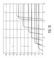
- the data throughput mainly depends on the MCS chosen for the transmission and the number of retransmissions. This is illustrated in FIG. 10 for the example of a Wireless Local Area Network (WLAN) according to the standard IEEE 802.11a. A similar figure could be derived for an UWB physical layer.
- WLAN Wireless Local Area Network
- FIG. 10 shows that the data throughput is a function of the Signal to Noise Ratio (SNR), which is mathematically designated as E av /N 0 in FIG. 10 .
- SNR Signal to Noise Ratio
- IEEE 802.11a there are 8 different MCS with data rates of 6, 9, 12, 18, 24, 36, 48 and 54 Mbit/s respectively.
- a lower robustness means that the achievable throughput drops at a higher SNR, as can be depicted from FIG. 10 . Taking the example of the lowest curve for a data rate 6 Mb it/s the throughput drops when the SNR falls below a level of approximately 4 dB.
- the throughput For the highest data rate of 54 Mbit/s the throughput already drops at and SNR of approximately 23 dB. The dropping of the throughput is due to retransmissions that have to be carried out when the data can no longer be reliably transmitted with a certain MCS.
- a strategy that maximizes the throughput would be to switch the MCS/data rate at the intersection points of two neighboring MCS, i.e. at certain SNR levels.
- the resulting throughput versus SNR would be the envelope of all curves in FIG. 10 , i.e. the maximum of all curves at a given SNR.
- a certain MCS/data rate would thus be employed in a pre-determined SNR interval.
- the receiver just has to calculate the current SNR and to read the appropriate MCS/data rate from a table in its local storage.
- the receiver can derive a recommendation to give as feedback to the sender.
- the TX power level can be determined in a similar way e.g. based on PER, RSS or also SNR.
- the sender could just use the MCS and TX Power that the receiver has recommended or could carry out an own estimation of the optimal MCS and TX Power and just use the recommendation of the receiver as one input for taking its decision.
Landscapes
- Engineering & Computer Science (AREA)
- Computer Networks & Wireless Communication (AREA)
- Signal Processing (AREA)
- Quality & Reliability (AREA)
- Mobile Radio Communication Systems (AREA)
- Communication Control (AREA)
- Small-Scale Networks (AREA)
Priority Applications (1)
| Application Number | Priority Date | Filing Date | Title |
|---|---|---|---|
| US11/577,537 US8081575B2 (en) | 2004-10-20 | 2005-10-19 | System and method for dynamic adaptation of data rate and transmit power with a beaconing protocol |
Applications Claiming Priority (4)
| Application Number | Priority Date | Filing Date | Title |
|---|---|---|---|
| US62044804P | 2004-10-20 | 2004-10-20 | |
| US66367005P | 2005-03-21 | 2005-03-21 | |
| US11/577,537 US8081575B2 (en) | 2004-10-20 | 2005-10-19 | System and method for dynamic adaptation of data rate and transmit power with a beaconing protocol |
| PCT/IB2005/053424 WO2006043242A1 (en) | 2004-10-20 | 2005-10-19 | A system and method for dynamic adaptation of data rate and transmit power with a beaconing protocol |
Publications (2)
| Publication Number | Publication Date |
|---|---|
| US20080137577A1 US20080137577A1 (en) | 2008-06-12 |
| US8081575B2 true US8081575B2 (en) | 2011-12-20 |
Family
ID=35788201
Family Applications (1)
| Application Number | Title | Priority Date | Filing Date |
|---|---|---|---|
| US11/577,537 Active 2028-01-26 US8081575B2 (en) | 2004-10-20 | 2005-10-19 | System and method for dynamic adaptation of data rate and transmit power with a beaconing protocol |
Country Status (13)
| Country | Link |
|---|---|
| US (1) | US8081575B2 (ru) |
| EP (1) | EP1805908B1 (ru) |
| JP (1) | JP4719748B2 (ru) |
| KR (1) | KR101127498B1 (ru) |
| AU (1) | AU2005297231B2 (ru) |
| BR (1) | BRPI0517087A8 (ru) |
| CA (1) | CA2584394C (ru) |
| EG (1) | EG25124A (ru) |
| MX (1) | MX2007004629A (ru) |
| MY (1) | MY145472A (ru) |
| RU (1) | RU2381622C2 (ru) |
| TW (1) | TWI375418B (ru) |
| WO (1) | WO2006043242A1 (ru) |
Cited By (9)
| Publication number | Priority date | Publication date | Assignee | Title |
|---|---|---|---|---|
| US20100220663A1 (en) * | 2005-06-10 | 2010-09-02 | Ntt Docomo, Inc. | Communications system and method |
| US20120140629A1 (en) * | 2010-12-02 | 2012-06-07 | Electronics And Telecommunications Research Institute | Routing method |
| US20120275420A1 (en) * | 2010-01-15 | 2012-11-01 | Huawei Technologies Co., Ltd. | Method and User Equipment for Feeding Back Multi-Cell Channel State Information |
| US8804590B2 (en) | 2010-12-20 | 2014-08-12 | Panasonic Corporation | Apparatus, method and implementation for adaptable wireless beacon communication system |
| US20150237663A1 (en) * | 2012-09-18 | 2015-08-20 | Telefonaktiebolaget L M Ericsson (Publ) | User equipment, a network node, and methods for device discovery in device-to-device (d2d) communications in a wireless telecommunications network |
| US9591007B2 (en) | 2014-11-06 | 2017-03-07 | International Business Machines Corporation | Detection of beaconing behavior in network traffic |
| US9686666B2 (en) | 2012-09-17 | 2017-06-20 | Telefonktiebolaget L M Ericsson (Publ) | Method and arrangement for handling D2D communication |
| US9736817B2 (en) | 2012-06-19 | 2017-08-15 | Telefonaktiebolaget L M Ericsson (Publ) | Method and arrangement for D2D discovery |
| US10284584B2 (en) | 2014-11-06 | 2019-05-07 | International Business Machines Corporation | Methods and systems for improving beaconing detection algorithms |
Families Citing this family (56)
| Publication number | Priority date | Publication date | Assignee | Title |
|---|---|---|---|---|
| US7584397B2 (en) * | 2004-06-10 | 2009-09-01 | Interdigital Technology Corporation | Method and apparatus for dynamically adjusting data transmission parameters and controlling H-ARQ processes |
| US8027327B2 (en) | 2004-06-25 | 2011-09-27 | Alcatel Lucent | Distributed scheduling in wireless networks with service differentiation |
| US7454218B2 (en) * | 2005-08-19 | 2008-11-18 | Panasonic Corporation | Method of band multiplexing to improve system capacity for a multi-band communication system |
| US9131371B2 (en) * | 2005-09-30 | 2015-09-08 | Alcatel Lucent | Method and apparatus for managing a random access communication system |
| JP4906315B2 (ja) * | 2005-10-31 | 2012-03-28 | キヤノン株式会社 | 通信制御装置、コンピュータの制御方法および制御プログラム |
| US7782817B2 (en) * | 2005-11-04 | 2010-08-24 | Intel Corporation | Systems and techniques for improved data throughput in a wireless network |
| KR101299732B1 (ko) * | 2006-07-14 | 2013-09-16 | 삼성전자주식회사 | 고주파 무선 대역에서의 무선 통신 방법 및 장치 |
| US20080031220A1 (en) * | 2006-08-03 | 2008-02-07 | Qualcomm Incorporated | Ofdm control signaling in the presence of timing asynchronization in a peer-to-peer network |
| US8040844B2 (en) * | 2006-11-20 | 2011-10-18 | Telecom Ventures, L.L.C. | Wireless communications apparatus and methods employing opportunistic frequency band use |
| JP4990369B2 (ja) | 2006-12-04 | 2012-08-01 | インターデイジタル テクノロジー コーポレーション | 次世代超広帯域技術におけるマルチ帯域伝送を可能にするための分散予約プロトコル |
| US8879448B2 (en) * | 2006-12-22 | 2014-11-04 | Samsung Electronics Co., Ltd. | Apparatus for controlling power of WiMedia media access control device and method using the same |
| JP5150645B2 (ja) * | 2007-01-19 | 2013-02-20 | コーニンクレッカ フィリップス エレクトロニクス エヌ ヴィ | ワイヤレス装置の発見を可能にする装置及び方法 |
| US20080192684A1 (en) * | 2007-02-09 | 2008-08-14 | Nokia Corporation | Access reservation in wireless communications |
| CN101247296A (zh) * | 2007-02-16 | 2008-08-20 | 华为技术有限公司 | 一种信标设备及信标状态指示方法及系统 |
| JP2008219498A (ja) * | 2007-03-05 | 2008-09-18 | Oki Electric Ind Co Ltd | 中継通信システム |
| US8170617B2 (en) | 2007-03-26 | 2012-05-01 | Sibeam, Inc. | Extensions to adaptive beam-steering method |
| US8005515B1 (en) * | 2007-04-04 | 2011-08-23 | Marvell World Trade Ltd. | Beacon miss prevention in power save modes using timing synchronization function |
| JP4930178B2 (ja) * | 2007-05-08 | 2012-05-16 | ソニー株式会社 | 無線通信装置、プログラム、無線通信方法および無線通信システム |
| JP4877059B2 (ja) * | 2007-05-08 | 2012-02-15 | ソニー株式会社 | 無線通信システム、無線通信装置、プログラムおよび無線通信方法 |
| GB2452753A (en) * | 2007-09-13 | 2009-03-18 | Iti Scotland Ltd | Channel switching in a communication network |
| US20090103435A1 (en) * | 2007-10-17 | 2009-04-23 | Nokia Corporation | Dynamic rate adaptation for distributed wireless network |
| US7986648B2 (en) | 2007-10-31 | 2011-07-26 | Qualcomm Incorporated | Methods and apparatus for communicating information using different types of symbols |
| KR100962533B1 (ko) * | 2007-12-17 | 2010-06-14 | 한국전자통신연구원 | 개인무선통신 네트워크에서 분산방식 매체접근제어자원할당 방법 및 장치 |
| KR101543194B1 (ko) | 2008-02-28 | 2015-08-07 | 애플 인크. | 무선 통신 시그널링에 적용되는 코딩을 식별하는 정보를 포함하는 피드백 데이터 구조체의 통신 |
| JP4553034B2 (ja) | 2008-05-22 | 2010-09-29 | ソニー株式会社 | 無線通信装置、プログラム、無線通信方法、および無線通信システム |
| JP5078793B2 (ja) * | 2008-07-29 | 2012-11-21 | 三菱電機株式会社 | 無線通信装置および中央制御無線通信装置 |
| EP2154829A1 (en) * | 2008-08-15 | 2010-02-17 | Thomson Licensing | Method for the adjustment of a transmission characteristic for a data transfer in a network of stations and first and second network station for the use in said method |
| EP2184880A1 (en) * | 2008-11-07 | 2010-05-12 | Thomson Licensing | A method of data rate adaptation for multicast communication |
| US9185585B2 (en) * | 2008-12-31 | 2015-11-10 | Telecom Italia S.P.A. | Method and system for simulating the physical level of a radio network |
| US20120147840A1 (en) * | 2008-12-31 | 2012-06-14 | Mediatek Inc. | Method for boosting downlink transmission to mobile station and system utilizing the same |
| EP2224776A3 (en) * | 2009-02-25 | 2014-01-22 | LG Electronics Inc. | method of exchanging messages between devices in a wireless network, and devices for the same |
| US8787468B2 (en) * | 2009-06-19 | 2014-07-22 | Motorola Mobility Llc | Method and apparatus for multi-radio coexistence |
| US20110199946A1 (en) * | 2010-02-17 | 2011-08-18 | Qualcomm Incorporated | Method and apparatus for supporting adaptive channel state information feedback rate in multi-user communication systems |
| US8520648B2 (en) * | 2010-06-14 | 2013-08-27 | Intel Corporation | Beacon transmission techniques in directional wireless networks |
| US8693495B2 (en) * | 2010-11-15 | 2014-04-08 | Hp Ventures A/S | Wireless network medium access control protocol |
| US8934466B2 (en) | 2010-12-16 | 2015-01-13 | Qualcomm Incorporated | Method and apparatus for supporting modulation-coding scheme set in very high throughput wireless systems |
| US9124347B2 (en) * | 2011-04-04 | 2015-09-01 | Qualcomm Incorporated | Systems and methods for communication in a white space |
| JP5938658B2 (ja) * | 2011-07-29 | 2016-06-22 | パナソニックIpマネジメント株式会社 | 無線通信端末及び通信制御方法 |
| JP2014017706A (ja) * | 2012-07-10 | 2014-01-30 | Ricoh Co Ltd | 無線通信装置およびプログラム、通信制御方法 |
| TWI478525B (zh) * | 2013-01-23 | 2015-03-21 | Academia Sinica | 多使用者多天線系統之傳送速率動態調節機制 |
| JP6142195B2 (ja) * | 2013-02-28 | 2017-06-07 | 株式会社国際電気通信基礎技術研究所 | 無線通信システム、無線基地局、無線通信方法、及びプログラム |
| CN104427619B (zh) * | 2013-09-10 | 2018-03-13 | 富士通株式会社 | 时隙分配方法和装置 |
| JP6374166B2 (ja) * | 2014-01-17 | 2018-08-15 | 株式会社Nttドコモ | 無線基地局、ユーザ端末及び無線通信方法 |
| CN103763072B (zh) * | 2014-01-23 | 2017-02-22 | 东南大学 | 一种mimo链路自适应传输方法 |
| WO2015191081A1 (en) * | 2014-06-13 | 2015-12-17 | Hewlett-Packard Development Company, L.P. | Motion-aware modulation and coding scheme adaptation |
| US9832673B2 (en) * | 2014-07-22 | 2017-11-28 | Qualcomm Incorporated | Ultra reliable link design |
| US20160029232A1 (en) * | 2014-07-22 | 2016-01-28 | Qualcomm Incorporated | Ultra reliable link design |
| US20160135083A1 (en) * | 2014-11-07 | 2016-05-12 | Newracom, Inc. | Method and apparatus for transmitting frames |
| US20170064633A1 (en) * | 2015-08-25 | 2017-03-02 | Qualcomm Incorporated | Power save mechanism in a wlan with large number of stations |
| US11044726B1 (en) * | 2017-01-10 | 2021-06-22 | Marvell Asia Pte, Ltd. | Selection of transmission parameters for acknowledgment packets |
| EP3707842B1 (en) * | 2017-11-10 | 2023-07-19 | QUALCOMM Incorporated | Autonomous modification of transmission parameters |
| US10924164B2 (en) | 2018-05-29 | 2021-02-16 | Skyworks Solutions, Inc. | Beamforming communication systems with power control based on antenna pattern configuration |
| US11418278B2 (en) * | 2019-09-23 | 2022-08-16 | Qualcomm Incorporated | Configured dependency between modulation and coding scheme (MCS) and power control |
| KR20230056622A (ko) * | 2020-08-24 | 2023-04-27 | 엘지전자 주식회사 | 무선 통신 시스템에서 단말 및 기지국의 신호 송수신 방법 및 장치 |
| US20230098347A1 (en) * | 2021-09-27 | 2023-03-30 | Cypress Semiconductor Corporation | Devices, systems and methods for throughput oriented association with access point devices |
| US20240040514A1 (en) * | 2022-08-01 | 2024-02-01 | Apple Inc. | Dynamic activation of network hardware based on real-time conditions |
Citations (2)
| Publication number | Priority date | Publication date | Assignee | Title |
|---|---|---|---|---|
| US20020172186A1 (en) | 2001-04-09 | 2002-11-21 | Peter Larsson | Instantaneous joint transmit power control and link adaptation for RTS/CTS based channel access |
| US7634275B2 (en) * | 2002-07-03 | 2009-12-15 | Freescale Semiconductor, Inc. | Method of accommodating periodic interfering signals in a wireless network |
Family Cites Families (4)
| Publication number | Priority date | Publication date | Assignee | Title |
|---|---|---|---|---|
| JP3262539B2 (ja) * | 1998-06-15 | 2002-03-04 | 株式会社ディジタル・ビジョン・ラボラトリーズ | データ放送方式及び同方式に適用されるデータ受信装置 |
| US6978151B2 (en) * | 2001-05-10 | 2005-12-20 | Koninklijke Philips Electronics N.V. | Updating path loss estimation for power control and link adaptation in IEEE 802.11h WLAN |
| US20030003905A1 (en) * | 2001-06-20 | 2003-01-02 | Shvodian William M. | System and method for providing signal quality feedback in a wireless network |
| US7184767B2 (en) * | 2001-11-28 | 2007-02-27 | Freescale Semiconductor, Inc. | System and method of communication between multiple point-coordinated wireless networks |
-
2005
- 2005-10-17 TW TW094136202A patent/TWI375418B/zh active
- 2005-10-18 MY MYPI20054892A patent/MY145472A/en unknown
- 2005-10-19 WO PCT/IB2005/053424 patent/WO2006043242A1/en active Application Filing
- 2005-10-19 RU RU2007118668/09A patent/RU2381622C2/ru active
- 2005-10-19 BR BRPI0517087A patent/BRPI0517087A8/pt not_active Application Discontinuation
- 2005-10-19 EP EP05792615.6A patent/EP1805908B1/en active Active
- 2005-10-19 JP JP2007537454A patent/JP4719748B2/ja active Active
- 2005-10-19 CA CA2584394A patent/CA2584394C/en active Active
- 2005-10-19 KR KR1020077008699A patent/KR101127498B1/ko active IP Right Grant
- 2005-10-19 US US11/577,537 patent/US8081575B2/en active Active
- 2005-10-19 AU AU2005297231A patent/AU2005297231B2/en not_active Ceased
- 2005-10-19 MX MX2007004629A patent/MX2007004629A/es active IP Right Grant
-
2007
- 2007-04-16 EG EGNA2007000382 patent/EG25124A/xx active
Patent Citations (2)
| Publication number | Priority date | Publication date | Assignee | Title |
|---|---|---|---|---|
| US20020172186A1 (en) | 2001-04-09 | 2002-11-21 | Peter Larsson | Instantaneous joint transmit power control and link adaptation for RTS/CTS based channel access |
| US7634275B2 (en) * | 2002-07-03 | 2009-12-15 | Freescale Semiconductor, Inc. | Method of accommodating periodic interfering signals in a wireless network |
Non-Patent Citations (1)
| Title |
|---|
| IEEE STD 802.15.3 Wireless Medium Access Control and Physical Layer Specifications for High Rate Wireless Personal Area Networks (WPANs) Part 15.3. pp. 1-208. |
Cited By (13)
| Publication number | Priority date | Publication date | Assignee | Title |
|---|---|---|---|---|
| US20100220663A1 (en) * | 2005-06-10 | 2010-09-02 | Ntt Docomo, Inc. | Communications system and method |
| US20120275420A1 (en) * | 2010-01-15 | 2012-11-01 | Huawei Technologies Co., Ltd. | Method and User Equipment for Feeding Back Multi-Cell Channel State Information |
| US8693441B2 (en) * | 2010-01-15 | 2014-04-08 | Huawei Technologies Co., Ltd. | Method and user equipment for feeding back multi-cell channel state information |
| US20120140629A1 (en) * | 2010-12-02 | 2012-06-07 | Electronics And Telecommunications Research Institute | Routing method |
| US8804590B2 (en) | 2010-12-20 | 2014-08-12 | Panasonic Corporation | Apparatus, method and implementation for adaptable wireless beacon communication system |
| US9736817B2 (en) | 2012-06-19 | 2017-08-15 | Telefonaktiebolaget L M Ericsson (Publ) | Method and arrangement for D2D discovery |
| US9686666B2 (en) | 2012-09-17 | 2017-06-20 | Telefonktiebolaget L M Ericsson (Publ) | Method and arrangement for handling D2D communication |
| US9860929B2 (en) * | 2012-09-18 | 2018-01-02 | Telefonaktiebolaget L M Ericsson (Publ) | User equipment, a network node, and methods for device discovery in device to-device (D2D) communications in a wireless telecommunications network |
| US20150237663A1 (en) * | 2012-09-18 | 2015-08-20 | Telefonaktiebolaget L M Ericsson (Publ) | User equipment, a network node, and methods for device discovery in device-to-device (d2d) communications in a wireless telecommunications network |
| US9591007B2 (en) | 2014-11-06 | 2017-03-07 | International Business Machines Corporation | Detection of beaconing behavior in network traffic |
| US10044737B2 (en) | 2014-11-06 | 2018-08-07 | International Business Machines Corporation | Detection of beaconing behavior in network traffic |
| US10284584B2 (en) | 2014-11-06 | 2019-05-07 | International Business Machines Corporation | Methods and systems for improving beaconing detection algorithms |
| US11153337B2 (en) | 2014-11-06 | 2021-10-19 | International Business Machines Corporation | Methods and systems for improving beaconing detection algorithms |
Also Published As
| Publication number | Publication date |
|---|---|
| JP2008517550A (ja) | 2008-05-22 |
| MY145472A (en) | 2012-02-15 |
| TWI375418B (en) | 2012-10-21 |
| KR20070083700A (ko) | 2007-08-24 |
| BRPI0517087A8 (pt) | 2018-05-08 |
| EG25124A (en) | 2011-09-18 |
| JP4719748B2 (ja) | 2011-07-06 |
| KR101127498B1 (ko) | 2012-03-23 |
| RU2381622C2 (ru) | 2010-02-10 |
| AU2005297231B2 (en) | 2010-05-27 |
| EP1805908B1 (en) | 2018-10-03 |
| RU2007118668A (ru) | 2008-11-27 |
| WO2006043242A1 (en) | 2006-04-27 |
| US20080137577A1 (en) | 2008-06-12 |
| CA2584394A1 (en) | 2006-04-27 |
| TW200637206A (en) | 2006-10-16 |
| BRPI0517087A (pt) | 2008-09-30 |
| EP1805908A1 (en) | 2007-07-11 |
| CA2584394C (en) | 2013-03-26 |
| AU2005297231A1 (en) | 2006-04-27 |
| MX2007004629A (es) | 2007-06-11 |
Similar Documents
| Publication | Publication Date | Title |
|---|---|---|
| US8081575B2 (en) | System and method for dynamic adaptation of data rate and transmit power with a beaconing protocol | |
| US6795407B2 (en) | Methods for controlling shared access to wireless transmission systems and increasing throughput of the same | |
| JP4679578B2 (ja) | 無線アドホックネットワークにおける分散リソース予約 | |
| AU2005210998B2 (en) | A system and method for an ultra wide-band medium access control distributed reservation protocol | |
| US7929546B2 (en) | Systems, methods and apparatus for allocating time slots in an ad hoc wireless communication network | |
| US7120126B2 (en) | Method for improved media quality feedback | |
| US20040264475A1 (en) | Class of high throughput MAC architectures for multi-channel CSMA systems | |
| CN101044695B (zh) | 用于通过信标协议进行数据速率和传输功率的动态自适应的系统和方法 | |
| KR100958227B1 (ko) | 통신 단말들 사이의 간섭을 제어하는 방법 | |
| EP3567972B1 (en) | Cocktail party: side conversations and talking over in wireless mesh networks | |
| WO2007008174A1 (en) | Method and system of wireless communication between devices | |
| WO2010024784A1 (en) | Methods and devices for requesting radio resources and/or synchronization within a radio communication system | |
| Kim et al. | A distributed cooperative MAC protocol for QoS improvement and mobility support in WiMedia networks | |
| WO2009088364A1 (en) | A method, a device and a computer program product for determining a data transmission characteristic | |
| Ghaboosi et al. | A novel topology aware MAC protocol for the next generation wireless ad hoc networks |
Legal Events
| Date | Code | Title | Description |
|---|---|---|---|
| AS | Assignment |
Owner name: KONINKLIJKE PHILIPS ELECTRONICS N.V., NETHERLANDS Free format text: ASSIGNMENT OF ASSIGNORS INTEREST;ASSIGNOR:HABETHA, JOERG;REEL/FRAME:019182/0900 Effective date: 20051121 |
|
| STCF | Information on status: patent grant |
Free format text: PATENTED CASE |
|
| FPAY | Fee payment |
Year of fee payment: 4 |
|
| MAFP | Maintenance fee payment |
Free format text: PAYMENT OF MAINTENANCE FEE, 8TH YEAR, LARGE ENTITY (ORIGINAL EVENT CODE: M1552); ENTITY STATUS OF PATENT OWNER: LARGE ENTITY Year of fee payment: 8 |
|
| MAFP | Maintenance fee payment |
Free format text: PAYMENT OF MAINTENANCE FEE, 12TH YEAR, LARGE ENTITY (ORIGINAL EVENT CODE: M1553); ENTITY STATUS OF PATENT OWNER: LARGE ENTITY Year of fee payment: 12 |