US8080750B2 - Device for mounting a switch or the like on a mounting plate - Google Patents
Device for mounting a switch or the like on a mounting plate Download PDFInfo
- Publication number
- US8080750B2 US8080750B2 US12/616,059 US61605909A US8080750B2 US 8080750 B2 US8080750 B2 US 8080750B2 US 61605909 A US61605909 A US 61605909A US 8080750 B2 US8080750 B2 US 8080750B2
- Authority
- US
- United States
- Prior art keywords
- mounting plate
- sleeve
- combination according
- opening
- fastening
- Prior art date
- Legal status (The legal status is an assumption and is not a legal conclusion. Google has not performed a legal analysis and makes no representation as to the accuracy of the status listed.)
- Expired - Fee Related, expires
Links
- 210000002105 tongue Anatomy 0.000 claims abstract description 32
- 210000002445 nipple Anatomy 0.000 claims description 5
- 210000000078 claw Anatomy 0.000 description 3
- 230000007812 deficiency Effects 0.000 description 1
- 238000003780 insertion Methods 0.000 description 1
- 230000037431 insertion Effects 0.000 description 1
Images


Classifications
-
- H—ELECTRICITY
- H02—GENERATION; CONVERSION OR DISTRIBUTION OF ELECTRIC POWER
- H02B—BOARDS, SUBSTATIONS OR SWITCHING ARRANGEMENTS FOR THE SUPPLY OR DISTRIBUTION OF ELECTRIC POWER
- H02B1/00—Frameworks, boards, panels, desks, casings; Details of substations or switching arrangements
- H02B1/015—Boards, panels, desks; Parts thereof or accessories therefor
- H02B1/04—Mounting thereon of switches or of other devices in general, the switch or device having, or being without, casing
- H02B1/044—Mounting through openings
- H02B1/048—Snap mounting
Definitions
- the present invention relates to a device for mounting a switch or the like on a mounting plate.
- the switch normally comprises a housing with a housing top side supported on the back side of the mounting plate, a fastening protrusion including fastening means, as well as a plurality of resilient tongues, each having a locking protrusion.
- the fastening protrusion and the resilient tongues are inserted from behind into an opening of the mounting plate.
- the locking protrusions thereby lock in place with the front edge of the opening.
- the device normally comprises a fastening element that can be mounted in a completing way from the front side of the mounting plate and cooperates with the fastening means of the fastening protrusion.
- the fastening protrusion is there configured as a sleeve.
- the resilient tongues are part of the sleeve wall and are each provided at their upper end with a locking protrusion.
- the sleeve is seated on the housing top side of the housing, which is here called a module carrier.
- the sleeve is inserted with the locking protrusions from behind into an opening of the mounting plate, the locking protrusions locking in place with the upper edge of the opening.
- the module carrier is here for example supported by a resilient element on the back side of the mounting plate.
- the sleeve comprises further locking protrusions that project beyond the upper edge of the mounting plate. The further locking protrusions serve to fix a cover.
- the fastening protrusion of this fastening device is also designed as a sleeve comprising a plurality of locking protrusions, which are here called claws.
- the sleeve is inserted from behind through a bore of a mounting plate, which is designated as a carrier, the claws being engaged on the front side by resilience. It is here also suggested that the sleeve should comprise further claws that project beyond the upper rim of the carrier bore and serve to retain a front plate covering the carrier bore, or a decorative ring.
- the switch is clamped with a tension ring against the back side of the carrier.
- a drawback of these devices known from the prior art is that a front plate mounted from the front or a mounted decorative ring or trim ring, also called a fastening element, must be made of a material with relatively high strength because this fastening element is held by locking protrusions that project beyond the upper rim of the mounting plate. Hence, the fastening element thereby forms a relatively large elevation for example of a control panel, which may be aesthetically undesirable. Moreover, this drawback may entail ergonomic deficiencies. Another drawback is that the tongues of the locking protrusions are relatively hard-sprung if a certain stability of the sleeve is to be ensured because the tongues themselves are part of the sleeve. A disassembly of the switch is therefore difficult and may also lead to irreparable damage in the case of correspondingly brittle materials. Likewise, the assembly of the switch may also turn out to be difficult, depending on the type of mounting plate.
- a device for mounting a switch if the resilient tongues extend from the housing top side substantially in a vertical direction and are spaced apart from the fastening projection, and the fastening element is formed by a sleeve that is insertable from the front side of the mounting plate into the opening of the mounting plate.
- the tongues can thus be configured to be relatively long, which entails ease of resilience of the tongues. This facilitates the assembly and disassembly of the switch.
- the fastening means can be mounted for holding the fastening element and the sleeve, respectively, also laterally on the fastening protrusion, whereby the minimum thickness of a decorative ring or the like is reduced.
- the opening of the mounting plate is formed by a bore.
- the sleeve comprises one cut-out per tongue. It turns out to be particularly advantageous when the outer diameter of the sleeve is about the diameter of the bore and if there is only a minor play between sleeve and bore. This ensures a firm seat of the sleeve and also of the switch, respectively. As an alternative, the outer diameter of the sleeve could also be smaller, so that the sleeve can be inserted or screwed into the gap between the fastening protrusion and the tongues.
- the sleeve is configured in the manner of a bayonet lock.
- the fastening means of the fastening protrusion are here formed by a plurality of nipples which cooperate with corresponding recesses of the sleeve.
- the sleeve is first introduced by insertion and is subsequently locked with a slight rotational movement by the nipples of the fastening protrusion and secured against falling out.
- the sleeve is provided on the cut-outs with wedge-shaped extensions which press the tongues of the locking protrusions by rotation of the bayonet lock against the rim of the opening.
- the sleeve comprises a decorative ring.
- the decorative ring is arranged on the upper end of the sleeve, thereby forming the only visible part of the sleeve after mounting.
- the decorative ring also serves supporting purposes against the front side of the mounting plate.
- the decorative ring therefore comprises grooves that serve to accommodate the locking protrusions. These grooves are provided on the bottom side and thus in the support area of the decorative ring.
- the tongues are uniformly arranged and distributed over the circumference of the bore.
- the housing exactly comprises four tongues. This ensures an adequate provisional hold on the mounting plate by engagement of the locking protrusions and simultaneously guarantees a good stability of the sleeve by just four cut-outs.
- the device further comprises a plurality of threaded pins seated in the housing. These threaded pins can be moved out of the housing top side by rotation and thereby serve to support the housing top side on the back side of the mounting plate. The tightening of the threaded pins caused by rotation is normally carried out as the last mounting step.
- FIG. 1 shows a switch with a configuration according to the invention of fastening protrusion and tongues
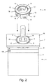
- FIG. 2 shows the switch of FIG. 1 inserted into the opening of a mounting plate, with a sleeve to be inserted;
- FIG. 3 is a side view of the finish-mounted switch of FIGS. 1 and 2 ;
- FIG. 4 is an oblique view of the sleeve according to the invention of FIGS. 2 and 3 .
- FIG. 1 shows a switch 1 in a design corresponding to the device according to the invention, in an oblique view.
- the switch 1 comprises a housing 2 with a housing top side 3 , a fastening protrusion 4 and four evenly distributed resilient tongues 5 , each having a locking protrusion 6 .
- the fastening protrusion 4 is designed as a circular round base and constitutes the bearing of the operating lever (not designated) of the switch 1 at the same time.
- the four resilient tongues 5 extend vertically from the housing top side 3 in the direction of the axis of the circular round fastening protrusion 4 and are spaced apart therefrom.
- the fastening protrusion 4 comprises four nipples 13 that are evenly distributed over the circumference and serve to hold the sleeve 11 , which is shown in FIG. 2 for the first time and configured in the manner of a bayonet lock.
- two accommodating means for accommodating threaded pins are provided with reference numeral 19 in FIG. 1 .
- FIG. 2 shows the switch of FIG. 1 already in the pre-mounted state.
- Fastening protrusion 4 and tongues 5 have already been inserted from behind into a bore 10 of the mounting plate 7 .
- the locking protrusions 6 arranged at the end of the tongues are thereby locked in place with the upper edge of the bore 10 and are thus positioned on the front side 8 of the mounting plate 7 .
- FIG. 2 shows the sleeve 11 , which is still to be inserted.
- the outer diameter of the sleeve 11 is approximately the same as the diameter of the bore 10 and the sleeve 11 comprises a cut-out 12 for each tongue 5 . It can thus be inserted from above into the clearance between the fastening protrusion 4 and the bore 10 .
- the nipples 13 shown in FIG. 1 thereby engage into the four recesses 14 of the sleeve 11 .
- the sleeve 11 configured in the manner of a bayonet lock is locked.
- the tongues 5 are pressed by the wedge-shaped extensions 15 of the sleeve 11 to the outside against the edge of the bore 10 , whereby a possible disengagement of the locking protrusions 6 is prevented.
- the sleeve 11 comprises a decorative ring 16 , which rests with its bottom side at least in part on the mounting plate 7 . The provisional hold provided by the engagement of the locking protrusions 6 is thereby intensified.
- FIG. 3 shows a side view of the finish-mounted switch illustrated in FIGS. 1 and 2 .
- the two threaded pins 18 which are seated in the accommodating means 19 of the housing 2 , are tightened by rotation, thereby supporting the switch 1 on the back side 9 of the mounting plate 7 .
- FIG. 4 shows an oblique bottom view of the sleeve 11 illustrated in FIGS. 2 to 3 .
- the decorative ring 16 is provided on its bottom side with four spirally outwardly oriented grooves 17 that serve to accommodate the locking protrusions 6 . Due to the spiral design of the grooves 17 the locking protrusions 6 are pressed in radial direction outwards against the edge of the bore 10 upon locking of the sleeve 11 configured in the manner of a bayonet lock. Hence, the grooves 17 provide further protection against any disengagement of the locking protrusions 6 .
Landscapes
- Engineering & Computer Science (AREA)
- Power Engineering (AREA)
- Switch Cases, Indication, And Locking (AREA)
- Connection Of Plates (AREA)
Abstract
Description
Claims (14)
Applications Claiming Priority (3)
| Application Number | Priority Date | Filing Date | Title |
|---|---|---|---|
| DE102008057147A DE102008057147B3 (en) | 2008-11-13 | 2008-11-13 | Device for mounting a switch or the like on a mounting plate |
| DE102008057147 | 2008-11-13 | ||
| DE102008057147.4 | 2008-11-13 |
Publications (2)
| Publication Number | Publication Date |
|---|---|
| US20100116957A1 US20100116957A1 (en) | 2010-05-13 |
| US8080750B2 true US8080750B2 (en) | 2011-12-20 |
Family
ID=41821561
Family Applications (1)
| Application Number | Title | Priority Date | Filing Date |
|---|---|---|---|
| US12/616,059 Expired - Fee Related US8080750B2 (en) | 2008-11-13 | 2009-11-10 | Device for mounting a switch or the like on a mounting plate |
Country Status (4)
| Country | Link |
|---|---|
| US (1) | US8080750B2 (en) |
| EP (1) | EP2190086A3 (en) |
| DE (1) | DE102008057147B3 (en) |
| RU (1) | RU2502165C2 (en) |
Cited By (1)
| Publication number | Priority date | Publication date | Assignee | Title |
|---|---|---|---|---|
| US20160053797A1 (en) * | 2014-08-20 | 2016-02-25 | Emerson Network Power, Energy Systems, North America, Inc. | Assemblies and methods for coupling components having slots and/or deformable stakes |
Families Citing this family (4)
| Publication number | Priority date | Publication date | Assignee | Title |
|---|---|---|---|---|
| IT1391302B1 (en) * | 2008-10-28 | 2011-12-01 | Elbi Int Spa | DETECTOR DEVICE OF THE LEVEL OF A LIQUID IN A CONTAINER, IN PARTICULAR OF THE WASHING BATH IN A WASHING MACHINE |
| DE102011101759B4 (en) | 2011-05-17 | 2016-04-21 | Schaltbau Gmbh | Device for mounting an electrical component, in particular a switch, on a mounting plate |
| DE102016213829A1 (en) * | 2016-07-27 | 2018-02-01 | Siemens Aktiengesellschaft | Available holding device for switchgear |
| JP6989149B2 (en) * | 2019-11-06 | 2022-01-05 | Necプラットフォームズ株式会社 | Parts mounting structure, parts mounting mating member, parts fixing member, and parts fixing method |
Citations (6)
| Publication number | Priority date | Publication date | Assignee | Title |
|---|---|---|---|---|
| DE2807798A1 (en) | 1977-02-24 | 1978-08-31 | Idec Izumi Corp | BRACKET FOR A COMPACT ELECTRICAL COMPONENT |
| DE8207613U1 (en) | 1982-02-11 | 1982-11-25 | Baco Constructions Electriques, 67024 Strasbourg | Rotary switch or the like with fastening device for attachment to the rear of a plate-shaped carrier |
| DE3406567A1 (en) | 1983-02-28 | 1984-09-27 | CGEE-Alsthom, Levallois-Perret | DEVICE FOR FASTENING AN OBJECT IN THE OPENING OF A WALL |
| US7217897B2 (en) * | 2004-12-10 | 2007-05-15 | Scoieta′ Europea Componenti Elettrici S.p.A. In Short S.E.C.E. S.p.A. | Backpanel insertion switch |
| US20070194190A1 (en) * | 2004-03-23 | 2007-08-23 | A. Raymond & Cie | Device to be fastened to a support which is provided with a threaded bolt |
| US7741572B2 (en) * | 2004-01-19 | 2010-06-22 | Abb Oy | Switching device module |
Family Cites Families (3)
| Publication number | Priority date | Publication date | Assignee | Title |
|---|---|---|---|---|
| SU1026217A1 (en) * | 1982-03-02 | 1983-06-30 | Ангарский электромеханический завод | Apparatus for fixing electric device |
| DE19832423B4 (en) * | 1998-06-09 | 2006-09-28 | Georg Schlegel Gmbh & Co. | Command or signaling device for installation in a control panel or the like |
| DE19959339A1 (en) * | 1999-12-09 | 2001-06-21 | Ellenberger & Poensgen | Electrical functional device, in particular circuit breaker, for use in aviation |
-
2008
- 2008-11-13 DE DE102008057147A patent/DE102008057147B3/en not_active Expired - Fee Related
-
2009
- 2009-07-28 EP EP09009754.4A patent/EP2190086A3/en not_active Withdrawn
- 2009-09-23 RU RU2009136384/07A patent/RU2502165C2/en not_active IP Right Cessation
- 2009-11-10 US US12/616,059 patent/US8080750B2/en not_active Expired - Fee Related
Patent Citations (6)
| Publication number | Priority date | Publication date | Assignee | Title |
|---|---|---|---|---|
| DE2807798A1 (en) | 1977-02-24 | 1978-08-31 | Idec Izumi Corp | BRACKET FOR A COMPACT ELECTRICAL COMPONENT |
| DE8207613U1 (en) | 1982-02-11 | 1982-11-25 | Baco Constructions Electriques, 67024 Strasbourg | Rotary switch or the like with fastening device for attachment to the rear of a plate-shaped carrier |
| DE3406567A1 (en) | 1983-02-28 | 1984-09-27 | CGEE-Alsthom, Levallois-Perret | DEVICE FOR FASTENING AN OBJECT IN THE OPENING OF A WALL |
| US7741572B2 (en) * | 2004-01-19 | 2010-06-22 | Abb Oy | Switching device module |
| US20070194190A1 (en) * | 2004-03-23 | 2007-08-23 | A. Raymond & Cie | Device to be fastened to a support which is provided with a threaded bolt |
| US7217897B2 (en) * | 2004-12-10 | 2007-05-15 | Scoieta′ Europea Componenti Elettrici S.p.A. In Short S.E.C.E. S.p.A. | Backpanel insertion switch |
Cited By (1)
| Publication number | Priority date | Publication date | Assignee | Title |
|---|---|---|---|---|
| US20160053797A1 (en) * | 2014-08-20 | 2016-02-25 | Emerson Network Power, Energy Systems, North America, Inc. | Assemblies and methods for coupling components having slots and/or deformable stakes |
Also Published As
| Publication number | Publication date |
|---|---|
| RU2502165C2 (en) | 2013-12-20 |
| RU2009136384A (en) | 2011-03-27 |
| US20100116957A1 (en) | 2010-05-13 |
| EP2190086A3 (en) | 2014-03-12 |
| DE102008057147B3 (en) | 2010-04-15 |
| EP2190086A2 (en) | 2010-05-26 |
Similar Documents
| Publication | Publication Date | Title |
|---|---|---|
| US8080750B2 (en) | Device for mounting a switch or the like on a mounting plate | |
| US7841782B2 (en) | Dome type camera with independently rotatable and lockable cover | |
| JP5616901B2 (en) | Spacer device and mounting structure including spacer device | |
| CN102046423B (en) | Bracket for motor vehicle accessories and device for holding motor vehicle accessories | |
| US7131806B2 (en) | Grommet and anchoring structure | |
| KR20140067889A (en) | Fastening clip | |
| CA2283606A1 (en) | Threaded ceiling hook with anti-rotation washer | |
| US7070306B2 (en) | Assembly for mounting a self-supporting spotlight on a stretched ceiling | |
| JP2013504174A (en) | Lamp unit | |
| EP2167280A1 (en) | Attachment mechanism | |
| US6314593B1 (en) | Sanitary fitting | |
| US8220968B2 (en) | Mount adjustable end cap clamp lock for lighting systems | |
| US20130049426A1 (en) | Seat adjustment apparatus | |
| US6283619B1 (en) | Lighting fixture assembly having locking arm components | |
| US20100006411A1 (en) | Switch attachment assembly | |
| US6783314B2 (en) | Fastener device | |
| CN111963947B (en) | Ceiling lamp | |
| US8356780B2 (en) | Foot base and foot for an appliance | |
| US9281665B2 (en) | Device for mounting a switch or the like on a mounting plate | |
| KR102321701B1 (en) | Insert nut for drawer | |
| GB2420702A (en) | Support bracket for camera housing | |
| EP4438935A1 (en) | A mounting bracket | |
| CN101779906B (en) | Locking device | |
| KR100939298B1 (en) | Leg of sink | |
| US20070017887A1 (en) | Rotary shelf assembly mechanism with pin adjustment means |
Legal Events
| Date | Code | Title | Description |
|---|---|---|---|
| AS | Assignment |
Owner name: SCHALTBAU GMBH,GERMANY Free format text: ASSIGNMENT OF ASSIGNORS INTEREST;ASSIGNORS:BAUER, HEINZ;BAUER, ANDREAS;REEL/FRAME:023852/0391 Effective date: 20091119 Owner name: SCHALTBAU GMBH, GERMANY Free format text: ASSIGNMENT OF ASSIGNORS INTEREST;ASSIGNORS:BAUER, HEINZ;BAUER, ANDREAS;REEL/FRAME:023852/0391 Effective date: 20091119 |
|
| STCF | Information on status: patent grant |
Free format text: PATENTED CASE |
|
| FEPP | Fee payment procedure |
Free format text: PAYOR NUMBER ASSIGNED (ORIGINAL EVENT CODE: ASPN); ENTITY STATUS OF PATENT OWNER: LARGE ENTITY |
|
| FPAY | Fee payment |
Year of fee payment: 4 |
|
| FEPP | Fee payment procedure |
Free format text: MAINTENANCE FEE REMINDER MAILED (ORIGINAL EVENT CODE: REM.); ENTITY STATUS OF PATENT OWNER: LARGE ENTITY |
|
| LAPS | Lapse for failure to pay maintenance fees |
Free format text: PATENT EXPIRED FOR FAILURE TO PAY MAINTENANCE FEES (ORIGINAL EVENT CODE: EXP.); ENTITY STATUS OF PATENT OWNER: LARGE ENTITY |
|
| STCH | Information on status: patent discontinuation |
Free format text: PATENT EXPIRED DUE TO NONPAYMENT OF MAINTENANCE FEES UNDER 37 CFR 1.362 |
|
| FP | Lapsed due to failure to pay maintenance fee |
Effective date: 20191220 |