US8079719B2 - Mirror scanning system - Google Patents
Mirror scanning system Download PDFInfo
- Publication number
- US8079719B2 US8079719B2 US12/043,246 US4324608A US8079719B2 US 8079719 B2 US8079719 B2 US 8079719B2 US 4324608 A US4324608 A US 4324608A US 8079719 B2 US8079719 B2 US 8079719B2
- Authority
- US
- United States
- Prior art keywords
- pair
- mirror
- flexure
- cylinders
- flexures
- Prior art date
- Legal status (The legal status is an assumption and is not a legal conclusion. Google has not performed a legal analysis and makes no representation as to the accuracy of the status listed.)
- Expired - Fee Related, expires
Links
Images


Classifications
-
- G—PHYSICS
- G02—OPTICS
- G02B—OPTICAL ELEMENTS, SYSTEMS OR APPARATUS
- G02B7/00—Mountings, adjusting means, or light-tight connections, for optical elements
- G02B7/18—Mountings, adjusting means, or light-tight connections, for optical elements for prisms; for mirrors
- G02B7/182—Mountings, adjusting means, or light-tight connections, for optical elements for prisms; for mirrors for mirrors
- G02B7/1821—Mountings, adjusting means, or light-tight connections, for optical elements for prisms; for mirrors for mirrors for rotating or oscillating mirrors
-
- G—PHYSICS
- G02—OPTICS
- G02B—OPTICAL ELEMENTS, SYSTEMS OR APPARATUS
- G02B26/00—Optical devices or arrangements for the control of light using movable or deformable optical elements
- G02B26/08—Optical devices or arrangements for the control of light using movable or deformable optical elements for controlling the direction of light
- G02B26/10—Scanning systems
- G02B26/101—Scanning systems with both horizontal and vertical deflecting means, e.g. raster or XY scanners
-
- G—PHYSICS
- G02—OPTICS
- G02B—OPTICAL ELEMENTS, SYSTEMS OR APPARATUS
- G02B7/00—Mountings, adjusting means, or light-tight connections, for optical elements
- G02B7/18—Mountings, adjusting means, or light-tight connections, for optical elements for prisms; for mirrors
- G02B7/182—Mountings, adjusting means, or light-tight connections, for optical elements for prisms; for mirrors for mirrors
- G02B7/1822—Mountings, adjusting means, or light-tight connections, for optical elements for prisms; for mirrors for mirrors comprising means for aligning the optical axis
- G02B7/1827—Motorised alignment
- G02B7/1828—Motorised alignment using magnetic means
Definitions
- the present invention relates generally to optical systems, and more specifically to an assembly that flexurally suspends a mirror to reflect millimeter wave energy to a radiometer.
- Mirrors are often used in imaging systems to direct electromagnetic radiation for various applications such as lasers, x-rays, and thermal imaging.
- the scanning mechanism that is the subject of this invention uses a flexurally suspended mirror in a millimeter wave imaging system.
- a millimeter wave imaging system uses either active or passive detection and measurement of electromagnetic radiation at millimeter wavelengths.
- the contrast in radiation between the surrounding background environment and individual undergoing a scan identifies concealed objects under clothing.
- the mirror In an adjustable mirror system, the mirror is used to scan the imaging zone and redirect millimeter wave energy to the focal plane of a lens. This reduces the required size of the radiometer.
- the mirror is mounted on a universal joint about two perpendicular axes.
- the universal joint provides the pivot point as actuators position the mirror as desired.
- this type of prior art system is not suited for scanning at a rapid rate.
- the universal joint is susceptible to failure and vibration as it becomes worn from use.
- the prior art describes an alternative mirror mount whereby a rod and flexible neck serve as a substitute for a universal joint to support the mirror. Actuators are used to tilt the mirror about the flexible neck and a diaphragm secures the mirror to the support body.
- a shortcoming of this type of system is the small field of scanning of less than 1 degree.
- the invention provides for a mirror scanning system with a mirror held substantially rigid in four degrees of freedom by two flexures, which permits rotation about the two remaining degrees of freedom.
- the mirror may be made of a honeycomb type material for lightness with rigidity.
- the system includes a pair of voice coil actuators aligned generally perpendicular to a mirror; a pair of corresponding cylinders secured to a center yoke, or moving coil bobbin, of each of the respective voice coil actuators; the pair of voice coil actuators having a circular flange disposed upon the periphery of the cylinders wherein the cylinders may be moved substantially axially by electrical current driven through the voice coil actuators by external amplifiers.
- Each cylinder is attached to a point on the mirror near its periphery by an actuator rod flexure, and drives the mirror to rotate about one of a pair of mutually perpendicular axes; and a base supporting a back plate generally disposed parallel to the mirror which mounts the voice coil actuators.
- the millimeter wave energy from an imaging zone is reflected by the mirror scanning system of the present invention to a radiometer. The millimeter wave energy is then processed to produce contrast-based images.
- a primary object of the invention is to provide lower fabrication costs of a mirror scanning system.
- Another very important object of the invention is to provide a mirror scanning system that has the ability to scan a large field of view.
- Still another important object of the invention is to provide an improved mirror scanning system that is accurate and not susceptible to wear of the assembly after normal operation.
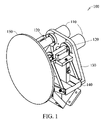
- FIG. 1 is a right perspective view of an embodiment of the present invention
- FIG. 2 is a left perspective view of an embodiment of the present invention
- FIG. 3 is an exploded view of an embodiment of the present invention.
- FIG. 4 is a perspective view of the voice coil flexure assembly in accordance with an embodiment of the present invention shown for clarity;
- FIG. 5 is a partial exploded view of the bottom portion of a voice coil flexure assembly showing how it is mounted to the base assembly in accordance with an embodiment of the present invention
- FIG. 6 is a partial view of the voice coil flexure and cylinder assembly in accordance with an embodiment of the present invention.
- FIG. 7 is a rear perspective view of an embodiment of the present invention.
- FIG. 8 is a front perspective view of the mirror assembly in accordance with an embodiment of the present invention.
- FIG. 9 is a side view of the mirror assembly in accordance with an embodiment of the present invention.
- FIG. 10 is a rear perspective view of the mirror assembly in accordance with an embodiment of the present invention.
- FIG. 11 is a partial view of the structure of the mirror assembly in accordance with an embodiment of the present invention.
- mirror scanning system 100 is shown in accordance with the present invention.
- a pair of voice coil actuators 110 are aligned generally perpendicular to mirror 150 .
- a pair of corresponding cylinders 120 are secured to a center yoke of each of the respective voice coils of the pair of voice coil actuators 110 using a circular flange disposed upon the periphery of cylinders 120 .
- Pair of cylinders 120 oscillate as voice coil actuators 110 are intermittently energized pursuant to a predetermined frequency related to a desired resolution.
- Base 140 provides the support for back plate 130 that secures pair of voice coil actuators 110 and is generally disposed parallel to mirror 150 .
- FIG. 2 shows a left perspective view of mirror scanning system 100 .
- First ends of actuator rod flexures 160 are attached to cylinders 120
- second ends of actuator rod flexures 160 are attached to the back side of mirror 150 .
- pair of voice coil actuators 110 are energized
- pair of actuator rod flexures 160 simultaneously exert a force on mirror 150 causing deflection thereon.
- Pair of voice coil actuators 110 are comprised of an outer stationary cylindrical housing and an internal movable yoke that slides within the cylindrical housing.
- Center rod mount 210 is located below pair of voice coil actuators 110 and mounted to the front face of back plate 130 , projecting rearward through the hole in back plate 130 .
- the center rod 215 is secured to a center portion of mirror 150 .
- a lower portion of front coil flexure 170 is secured to base 140 by base flexure mount 180 .
- the upper portion of front coil flexure 170 is secured to the front portion of pair of cylinders 120 .
- the upper portion of rear coil flexure 175 is secured to the rear portion of pair of cylinders 120 .
- Rear coil flexures 175 act in pairs to guide the voice coils of the voice coil actuators 110 .
- Stoppers 250 are mounted to the front portion of back plate 130 and are disposed so as to restrict the forward range of motion for pair of cylinders 120 .
- the apex of inverted V-shaped mirror support flexure 155 is secured to the center of mirror 150 and the legs of mirror support flexure 155 are secured to base 140 . Accordingly, mirror 150 is flexurally suspended.
- a position sensor 190 is mounted to each sensor bracket 230 , which is adjacent to each cylinder of pair of cylinders 120 .
- Sensor 190 is used to determine precisely the axial positions of cylinders 120 and actuator rod flexures 160 and hence the angles of mirror 150 .
- sensor 190 is a high-resolution glass scale position sensor.
- Scale 240 is mounted to cylinder 120 so that sensor 190 can determine the position of cylinder 120 .
- sensor 190 is a low-resolution metal scale sensor or a photo-reflective limit switch.
- FIG. 4 is a perspective view of the coil flexure assembly wherein elements are removed for clarity.
- Lower portion of back plate 130 is mounted to base 140 .
- Rear coil flexure 175 and front coil flexure 170 comprise triangular planar frames, which are flexible in the out-of-plane direction. There is an aperture at the apex of each triangular frame to allow a continuous path for the pair of rod flexures between the pair of corresponding voice coils and mirror.
- the periphery of the rear surface of each of the apexes of the rear coil flexure 175 is attached to the internal yoke of a corresponding voice coil, which passes through a corresponding aperture in back plate 130 .
- a flange along the periphery of the rear surface of cylinder 120 is attached to the periphery of the front surface of each of the apexes of the rear coil flexure 175 .
- front coil flexure 170 is attached to the front portion of base 140 . Similar to rear coil flexure 175 , front coil flexure 170 comprises a matching pair of apertures disposed at the apex of each triangular member. The pair of apertures allows a continuous path for pair of rod flexures between the pair of corresponding voice coils and the mirror. As shown in FIG. 5 , the lower portion of front flexures 170 is secured to base 140 with clamp bar 260 . A pair of opposing horizontal notches are disposed in the lower member of front coil flexure 170 and matching bosses are disposed on base 140 . Bosses accurately locate front coil flexure 170 vertically, while the vertical notch on the lower member mates with the corresponding boss on base 140 to accurately locate front coil flexure 170 laterally.
- FIG. 6 shows the upper portion of front flexure 170 attached to cylinder 120 .
- Sensor mounting bracket 230 is attached to sensor bracket mount 220 .
- Sensor 190 is supported on a top surface of mounting bracket 230 .
- the rear portion of cylinder 120 has a circular flange about its periphery that is adapted to be secured to the internal yoke of the voice coil that moves cylinder 120 in an axial fashion which in turn moves rear coil flexure and front flexure 170 as the voice coil is intermittently energized.
- FIG. 7 shows a rear perspective view of mirror scanning system 100 .
- Pair of actuator rod flexures 160 are attached to the rear portion of mirror 150 .
- Mirror 150 is mounted resiliently and is deflected as force is applied by rod flexures 160 .
- FIG. 8 shows a front perspective view of mirror 150 having a reflective circular front surface 130 .
- FIG. 9 is a side view of mirror 150 showing the structure supporting reflective front surface 130 .
- Ribs 320 are disposed in radial fashion about the center location of mirror 150 .
- pair of mounting bosses 330 are used to secure pair of actuator rod flexures 160 to mirror 150 .
- Center mounting boss 340 allows for the center rod 215 and V-shaped mirror support flexure 155 to be attached to mirror 150 and about which mirror 150 oscillates.
- FIG. 11 shows an alternative construction for mirror 150 , using a honeycomb sandwich material for the primary mirror structure, with bosses 330 and 340 bonded to it for the attachment of actuator rod flexures 160 and 215 . This construction is significantly lighter and cheaper than the machined construction.
Landscapes
- Physics & Mathematics (AREA)
- General Physics & Mathematics (AREA)
- Optics & Photonics (AREA)
- Mechanical Optical Scanning Systems (AREA)
Abstract
Description
Claims (10)
Priority Applications (1)
| Application Number | Priority Date | Filing Date | Title |
|---|---|---|---|
| US12/043,246 US8079719B2 (en) | 2008-03-06 | 2008-03-06 | Mirror scanning system |
Applications Claiming Priority (1)
| Application Number | Priority Date | Filing Date | Title |
|---|---|---|---|
| US12/043,246 US8079719B2 (en) | 2008-03-06 | 2008-03-06 | Mirror scanning system |
Publications (2)
| Publication Number | Publication Date |
|---|---|
| US20090225382A1 US20090225382A1 (en) | 2009-09-10 |
| US8079719B2 true US8079719B2 (en) | 2011-12-20 |
Family
ID=41053316
Family Applications (1)
| Application Number | Title | Priority Date | Filing Date |
|---|---|---|---|
| US12/043,246 Expired - Fee Related US8079719B2 (en) | 2008-03-06 | 2008-03-06 | Mirror scanning system |
Country Status (1)
| Country | Link |
|---|---|
| US (1) | US8079719B2 (en) |
Families Citing this family (12)
| Publication number | Priority date | Publication date | Assignee | Title |
|---|---|---|---|---|
| US20100259805A1 (en) * | 2009-04-13 | 2010-10-14 | Molecular Devices, Inc. | Methods and systems for reducing scanner image distortion |
| NL1039643C2 (en) * | 2012-06-01 | 2013-12-04 | Janssen Prec Engineering | Optical chopper with combined tip/tilt movement. |
| US20140061420A1 (en) * | 2012-08-20 | 2014-03-06 | National Security Technologies, Llc | Slit Diaphragm Flexure |
| JP2014123020A (en) * | 2012-12-21 | 2014-07-03 | Seiko Epson Corp | Actuator, optical scanner, image display apparatus and head-mounted display |
| CN107505799B (en) * | 2017-09-18 | 2020-04-10 | 北京空间飞行器总体设计部 | Concentrated point type stressed load supporting structure |
| US12204050B2 (en) | 2018-09-14 | 2025-01-21 | Magna Electronics, Llc | Scanning assembly for a detection system |
| US11307294B2 (en) * | 2018-09-14 | 2022-04-19 | Veoneer Us, Inc. | Scanning assembly for a detection system |
| CN114415366A (en) * | 2022-02-16 | 2022-04-29 | 四川中科朗星光电科技有限公司 | Fast reflection mirror mechanism based on voice coil motor |
| CN115728905B (en) * | 2022-11-24 | 2024-08-30 | 中国科学院西安光学精密机械研究所 | A reflector surface shape control device |
| CN116699793B (en) * | 2023-08-09 | 2023-10-20 | 北京瑞控信科技股份有限公司 | Quick reflector based on memory alloy locking structure |
| CN116909013B (en) * | 2023-09-05 | 2023-12-29 | 北京瑞控信科技股份有限公司 | A hollow rapid reflector |
| CN119805735B (en) * | 2025-03-17 | 2025-05-13 | 成都浩孚科技有限公司 | Photoelectric pod adjusting device and method |
Citations (1)
| Publication number | Priority date | Publication date | Assignee | Title |
|---|---|---|---|---|
| US20050046979A1 (en) * | 2003-06-24 | 2005-03-03 | Dave Hiley | Precision mirror displacement assembly |
-
2008
- 2008-03-06 US US12/043,246 patent/US8079719B2/en not_active Expired - Fee Related
Patent Citations (1)
| Publication number | Priority date | Publication date | Assignee | Title |
|---|---|---|---|---|
| US20050046979A1 (en) * | 2003-06-24 | 2005-03-03 | Dave Hiley | Precision mirror displacement assembly |
Also Published As
| Publication number | Publication date |
|---|---|
| US20090225382A1 (en) | 2009-09-10 |
Similar Documents
| Publication | Publication Date | Title |
|---|---|---|
| US8079719B2 (en) | Mirror scanning system | |
| US10663754B2 (en) | Optical unit with shake correction function structured to swing optical element | |
| CN110955095B (en) | Multi-axis optical image stabilization and focusing device, camera module and electronic device | |
| US6844952B2 (en) | Actuator-controlled mirror with Z-stop mechanism | |
| WO2009133691A1 (en) | Optical unit with vibration correction function | |
| JP2009288770A (en) | Optical unit with vibration correction function | |
| JP5949972B1 (en) | Imaging device | |
| KR20120055573A (en) | Holding arrangement for an optical element | |
| JPH09101464A (en) | Device for accurately positioning vertex of off-centered second reflecting mirror with regard to vertex of first reflecting mirror of telescope and telescope having device thereof | |
| JP2015121755A (en) | Image shake correction device, lens device, and imaging device | |
| KR101704204B1 (en) | Three-dimensional shape measurement apparatus | |
| CN108931875B (en) | Biaxial tilting devices, photographic devices, optical devices and electronic equipment | |
| JP7554753B2 (en) | Tiltable folding mirror for optical imaging systems - Patents.com | |
| CN109283654A (en) | A one-dimensional fast mirror device | |
| US6967792B2 (en) | Apparatus for positioning an optical element in a structure | |
| US7733586B2 (en) | Lens positioning assembly | |
| US10928644B2 (en) | Anti-vibration device and binocle | |
| US7573626B2 (en) | Optical scanner and image display apparatus having the same | |
| CN208953763U (en) | A one-dimensional fast mirror device | |
| JPH0882757A (en) | 2-axis luminous flux drive | |
| JP6989311B2 (en) | Optical unit with runout correction function | |
| CN212364723U (en) | Two-dimensional projection image generating device | |
| CN105043550A (en) | Double-arm sweep pendulum type interferometer system | |
| CN110967800B (en) | Lens driving device, camera device and electronic equipment | |
| JP2663543B2 (en) | Secondary mirror vibration device |
Legal Events
| Date | Code | Title | Description |
|---|---|---|---|
| AS | Assignment |
Owner name: BRIJOT IMAGING SYSTEMS, INC., FLORIDA Free format text: ASSIGNMENT OF ASSIGNORS INTEREST;ASSIGNORS:MILLER, WARREN H.;WHITE, KENNETH D.;WARD, REEDER N.;REEL/FRAME:020607/0637 Effective date: 20080104 |
|
| AS | Assignment |
Owner name: MICROSEMI CORPORATION, CALIFORNIA Free format text: ASSIGNMENT OF ASSIGNORS INTEREST;ASSIGNOR:BRIJOT IMAGING SYSTEMS, INC.;REEL/FRAME:026691/0129 Effective date: 20110802 |
|
| AS | Assignment |
Owner name: MORGAN STANLEY & CO. LLC, NEW YORK Free format text: SUPPLEMENTAL PATENT SECURITY AGREEMENT;ASSIGNORS:MICROSEMI CORPORATION;MICROSEMI CORP. - ANALOG MIXED SIGNAL GROUP;MICROSEMI CORP. - MASSACHUSETTS;AND OTHERS;REEL/FRAME:027213/0611 Effective date: 20111026 |
|
| FEPP | Fee payment procedure |
Free format text: PAYOR NUMBER ASSIGNED (ORIGINAL EVENT CODE: ASPN); ENTITY STATUS OF PATENT OWNER: LARGE ENTITY |
|
| AS | Assignment |
Owner name: BANK OF AMERICA, N.A., AS SUCCESSOR AGENT, NORTH C Free format text: NOTICE OF SUCCESSION OF AGENCY;ASSIGNOR:ROYAL BANK OF CANADA (AS SUCCESSOR TO MORGAN STANLEY & CO. LLC);REEL/FRAME:035657/0223 Effective date: 20150402 |
|
| REMI | Maintenance fee reminder mailed | ||
| LAPS | Lapse for failure to pay maintenance fees | ||
| STCH | Information on status: patent discontinuation |
Free format text: PATENT EXPIRED DUE TO NONPAYMENT OF MAINTENANCE FEES UNDER 37 CFR 1.362 |
|
| STCH | Information on status: patent discontinuation |
Free format text: PATENT EXPIRED DUE TO NONPAYMENT OF MAINTENANCE FEES UNDER 37 CFR 1.362 |
|
| AS | Assignment |
Owner name: MICROSEMI CORP.-ANALOG MIXED SIGNAL GROUP, A DELAWARE CORPORATION, CALIFORNIA Free format text: RELEASE BY SECURED PARTY;ASSIGNOR:BANK OF AMERICA, N.A.;REEL/FRAME:037558/0711 Effective date: 20160115 Owner name: MICROSEMI SOC CORP., A CALIFORNIA CORPORATION, CALIFORNIA Free format text: RELEASE BY SECURED PARTY;ASSIGNOR:BANK OF AMERICA, N.A.;REEL/FRAME:037558/0711 Effective date: 20160115 Owner name: MICROSEMI SEMICONDUCTOR (U.S.) INC., A DELAWARE CORPORATION, CALIFORNIA Free format text: RELEASE BY SECURED PARTY;ASSIGNOR:BANK OF AMERICA, N.A.;REEL/FRAME:037558/0711 Effective date: 20160115 Owner name: MICROSEMI FREQUENCY AND TIME CORPORATION, A DELAWARE CORPORATION, CALIFORNIA Free format text: RELEASE BY SECURED PARTY;ASSIGNOR:BANK OF AMERICA, N.A.;REEL/FRAME:037558/0711 Effective date: 20160115 Owner name: MICROSEMI COMMUNICATIONS, INC. (F/K/A VITESSE SEMICONDUCTOR CORPORATION), A DELAWARE CORPORATION, CALIFORNIA Free format text: RELEASE BY SECURED PARTY;ASSIGNOR:BANK OF AMERICA, N.A.;REEL/FRAME:037558/0711 Effective date: 20160115 Owner name: MICROSEMI CORP.-MEMORY AND STORAGE SOLUTIONS (F/K/A WHITE ELECTRONIC DESIGNS CORPORATION), AN INDIANA CORPORATION, CALIFORNIA Free format text: RELEASE BY SECURED PARTY;ASSIGNOR:BANK OF AMERICA, N.A.;REEL/FRAME:037558/0711 Effective date: 20160115 Owner name: MICROSEMI FREQUENCY AND TIME CORPORATION, A DELAWA Free format text: RELEASE BY SECURED PARTY;ASSIGNOR:BANK OF AMERICA, N.A.;REEL/FRAME:037558/0711 Effective date: 20160115 Owner name: MICROSEMI CORP.-MEMORY AND STORAGE SOLUTIONS (F/K/ Free format text: RELEASE BY SECURED PARTY;ASSIGNOR:BANK OF AMERICA, N.A.;REEL/FRAME:037558/0711 Effective date: 20160115 Owner name: MICROSEMI SEMICONDUCTOR (U.S.) INC., A DELAWARE CO Free format text: RELEASE BY SECURED PARTY;ASSIGNOR:BANK OF AMERICA, N.A.;REEL/FRAME:037558/0711 Effective date: 20160115 Owner name: MICROSEMI CORPORATION, CALIFORNIA Free format text: RELEASE BY SECURED PARTY;ASSIGNOR:BANK OF AMERICA, N.A.;REEL/FRAME:037558/0711 Effective date: 20160115 Owner name: MICROSEMI COMMUNICATIONS, INC. (F/K/A VITESSE SEMI Free format text: RELEASE BY SECURED PARTY;ASSIGNOR:BANK OF AMERICA, N.A.;REEL/FRAME:037558/0711 Effective date: 20160115 Owner name: MICROSEMI CORP.-ANALOG MIXED SIGNAL GROUP, A DELAW Free format text: RELEASE BY SECURED PARTY;ASSIGNOR:BANK OF AMERICA, N.A.;REEL/FRAME:037558/0711 Effective date: 20160115 Owner name: MICROSEMI SOC CORP., A CALIFORNIA CORPORATION, CAL Free format text: RELEASE BY SECURED PARTY;ASSIGNOR:BANK OF AMERICA, N.A.;REEL/FRAME:037558/0711 Effective date: 20160115 |
|
| FP | Lapsed due to failure to pay maintenance fee |
Effective date: 20151220 |