US8078935B2 - Method and system for encoding and decoding information with modulation constraints and error control - Google Patents
Method and system for encoding and decoding information with modulation constraints and error control Download PDFInfo
- Publication number
- US8078935B2 US8078935B2 US11/796,094 US79609407A US8078935B2 US 8078935 B2 US8078935 B2 US 8078935B2 US 79609407 A US79609407 A US 79609407A US 8078935 B2 US8078935 B2 US 8078935B2
- Authority
- US
- United States
- Prior art keywords
- code
- parity
- constrained
- words
- word
- Prior art date
- Legal status (The legal status is an assumption and is not a legal conclusion. Google has not performed a legal analysis and makes no representation as to the accuracy of the status listed.)
- Expired - Fee Related, expires
Links
- 238000000034 method Methods 0.000 title claims abstract description 93
- 238000013461 design Methods 0.000 claims abstract description 32
- 230000003287 optical effect Effects 0.000 claims abstract description 28
- 239000011159 matrix material Substances 0.000 claims abstract description 15
- 230000009897 systematic effect Effects 0.000 claims abstract description 13
- 238000000638 solvent extraction Methods 0.000 claims 2
- 238000012937 correction Methods 0.000 abstract description 15
- 238000001514 detection method Methods 0.000 abstract description 11
- 238000012805 post-processing Methods 0.000 abstract description 5
- 230000008569 process Effects 0.000 description 9
- 238000013459 approach Methods 0.000 description 6
- 238000010586 diagram Methods 0.000 description 5
- 230000004044 response Effects 0.000 description 5
- 238000013500 data storage Methods 0.000 description 4
- 230000005291 magnetic effect Effects 0.000 description 4
- 230000007704 transition Effects 0.000 description 3
- 101100400452 Caenorhabditis elegans map-2 gene Proteins 0.000 description 2
- 238000007476 Maximum Likelihood Methods 0.000 description 2
- 238000004891 communication Methods 0.000 description 2
- 238000011161 development Methods 0.000 description 2
- 238000011156 evaluation Methods 0.000 description 2
- 230000006870 function Effects 0.000 description 2
- 238000013507 mapping Methods 0.000 description 2
- 238000012545 processing Methods 0.000 description 2
- 230000008901 benefit Effects 0.000 description 1
- 238000004364 calculation method Methods 0.000 description 1
- 238000005094 computer simulation Methods 0.000 description 1
- 239000000470 constituent Substances 0.000 description 1
- 230000002708 enhancing effect Effects 0.000 description 1
- 238000001914 filtration Methods 0.000 description 1
- 230000006872 improvement Effects 0.000 description 1
- 230000010354 integration Effects 0.000 description 1
- 238000012986 modification Methods 0.000 description 1
- 230000004048 modification Effects 0.000 description 1
- 238000007781 pre-processing Methods 0.000 description 1
- 238000011084 recovery Methods 0.000 description 1
- 238000004088 simulation Methods 0.000 description 1
- 238000010561 standard procedure Methods 0.000 description 1
- 208000011580 syndromic disease Diseases 0.000 description 1
- 238000012546 transfer Methods 0.000 description 1
Images


Classifications
-
- G—PHYSICS
- G11—INFORMATION STORAGE
- G11B—INFORMATION STORAGE BASED ON RELATIVE MOVEMENT BETWEEN RECORD CARRIER AND TRANSDUCER
- G11B20/00—Signal processing not specific to the method of recording or reproducing; Circuits therefor
- G11B20/10—Digital recording or reproducing
- G11B20/18—Error detection or correction; Testing, e.g. of drop-outs
- G11B20/1833—Error detection or correction; Testing, e.g. of drop-outs by adding special lists or symbols to the coded information
-
- G—PHYSICS
- G11—INFORMATION STORAGE
- G11B—INFORMATION STORAGE BASED ON RELATIVE MOVEMENT BETWEEN RECORD CARRIER AND TRANSDUCER
- G11B20/00—Signal processing not specific to the method of recording or reproducing; Circuits therefor
- G11B20/10—Digital recording or reproducing
- G11B20/10009—Improvement or modification of read or write signals
- G11B20/10268—Improvement or modification of read or write signals bit detection or demodulation methods
- G11B20/10287—Improvement or modification of read or write signals bit detection or demodulation methods using probabilistic methods, e.g. maximum likelihood detectors
- G11B20/10296—Improvement or modification of read or write signals bit detection or demodulation methods using probabilistic methods, e.g. maximum likelihood detectors using the Viterbi algorithm
-
- H—ELECTRICITY
- H03—ELECTRONIC CIRCUITRY
- H03M—CODING; DECODING; CODE CONVERSION IN GENERAL
- H03M13/00—Coding, decoding or code conversion, for error detection or error correction; Coding theory basic assumptions; Coding bounds; Error probability evaluation methods; Channel models; Simulation or testing of codes
- H03M13/03—Error detection or forward error correction by redundancy in data representation, i.e. code words containing more digits than the source words
- H03M13/05—Error detection or forward error correction by redundancy in data representation, i.e. code words containing more digits than the source words using block codes, i.e. a predetermined number of check bits joined to a predetermined number of information bits
- H03M13/11—Error detection or forward error correction by redundancy in data representation, i.e. code words containing more digits than the source words using block codes, i.e. a predetermined number of check bits joined to a predetermined number of information bits using multiple parity bits
-
- H—ELECTRICITY
- H03—ELECTRONIC CIRCUITRY
- H03M—CODING; DECODING; CODE CONVERSION IN GENERAL
- H03M13/00—Coding, decoding or code conversion, for error detection or error correction; Coding theory basic assumptions; Coding bounds; Error probability evaluation methods; Channel models; Simulation or testing of codes
- H03M13/31—Coding, decoding or code conversion, for error detection or error correction; Coding theory basic assumptions; Coding bounds; Error probability evaluation methods; Channel models; Simulation or testing of codes combining coding for error detection or correction and efficient use of the spectrum
-
- H—ELECTRICITY
- H03—ELECTRONIC CIRCUITRY
- H03M—CODING; DECODING; CODE CONVERSION IN GENERAL
- H03M5/00—Conversion of the form of the representation of individual digits
- H03M5/02—Conversion to or from representation by pulses
- H03M5/04—Conversion to or from representation by pulses the pulses having two levels
- H03M5/14—Code representation, e.g. transition, for a given bit cell depending on the information in one or more adjacent bit cells, e.g. delay modulation code, double density code
- H03M5/145—Conversion to or from block codes or representations thereof
-
- G—PHYSICS
- G11—INFORMATION STORAGE
- G11B—INFORMATION STORAGE BASED ON RELATIVE MOVEMENT BETWEEN RECORD CARRIER AND TRANSDUCER
- G11B20/00—Signal processing not specific to the method of recording or reproducing; Circuits therefor
- G11B20/10—Digital recording or reproducing
- G11B20/12—Formatting, e.g. arrangement of data block or words on the record carriers
- G11B2020/1264—Formatting, e.g. arrangement of data block or words on the record carriers wherein the formatting concerns a specific kind of data
- G11B2020/1288—Formatting by padding empty spaces with dummy data, e.g. writing zeroes or random data when de-icing optical discs
-
- G—PHYSICS
- G11—INFORMATION STORAGE
- G11B—INFORMATION STORAGE BASED ON RELATIVE MOVEMENT BETWEEN RECORD CARRIER AND TRANSDUCER
- G11B2220/00—Record carriers by type
- G11B2220/20—Disc-shaped record carriers
- G11B2220/25—Disc-shaped record carriers characterised in that the disc is based on a specific recording technology
- G11B2220/2537—Optical discs
- G11B2220/2541—Blu-ray discs; Blue laser DVR discs
Definitions
- the present invention relates to encoding and/or decoding information, for instance in optical recording systems. More particularly, the invention provides a method and system of coding information with improved information density, by imposing both modulation constraints and parity-check constraints in channel coded data sequences.
- Modulation codes also known as constrained codes, are used in recording systems to translate an arbitrary sequence of user data into a sequence with special properties required by the relevant systems.
- Two major constraints for optical recording systems are run-length constraints, or (d, k) constraints, and the dc-free constraint.
- the run-length constraints bound the minimal and/or maximal lengths of runs of zeros in an encoded data stream, to mitigate the problems of intersymbol interference and inaccurate timing.
- the dc-free constraint avoids interference between data and servo signals, and also permits filtering of low-frequency disk noise, such as finger marks on the disk surface.
- Coding and signal processing techniques play a key role in the development of high density and high speed optical recording systems.
- the parity-check codes based approach has found wide acceptance in data storage systems, since the performance-complexity trade-off offered by these codes is very attractive and affordable. Therefore, it is one of the most promising reception techniques for so-called ‘fourth generation’ optical storage systems.
- Parity-check codes may be classified into single-bit parity-check codes and multiple-bit parity-check codes.
- a single-bit parity-check code with even (or odd) parity-check is a simple and basic code, which can detect only a few types of error events.
- Concatenated coding is further proposed to construct modulation codes with error detection and correction capabilities, as discussed in S. Gopalaswamy and J. W. M. Bergmans, “Modified target and concatenated Coding for constrained magnetic recording channels,” in Proc. IEEE Intl. Conf. Commun. (ICC), New La, USA, June 2000, pp. 89-93 and H. Sawaguchi, S. Mita, and J. K. Wolf, “A concatenated coding technique for partial response channels,” IEEE Trans. Magnetics, vol. 37, No. 2, pp. 695-703, March 2001.
- parity-check information is first calculated for each modulation coded data block.
- the concatenated coding scheme achieves high coding efficiency.
- a parity-check bit requires 2 channel bits.
- a parity-check bit requires 1.5 channel bits.
- the concatenated coding scheme has two drawbacks: (i) during decoding, local demodulation is needed to derive the parity-checks. Thus, part of the channel bit-stream corresponding to the parity-check bits needs to be modulation decoded first, before the parity-check information for the combined data block can be obtained. Obviously, this will increase the decoding complexity. (ii) the channel bit-stream corresponding to the parity-check bits is not protected by parity-checks. Therefore, errors occurring in the parity-related data block may lead to further errors during the decoding of the whole data block. Thus results in error propagation.
- the constrained parity-check code consists of a set of two sliding block codes: a standard code and a parity-check enabling code.
- the leading part of the constrained parity-check code includes several standard codes, which are chosen to be conventional constrained codes.
- the combi-code scheme has several drawbacks.
- the combi-code scheme is designed to correct a specific type of error event (i.e. single-bit transition shift error, or n-bit transition shift errors in the same direction). It is difficult to generalise the scheme to detect an arbitrary type of error event as well as error event combinations.
- the disadvantage of a time-varying encoder is that, for each phase of the encoder, a separate code is required. This will cause significant increases in the implementation complexity.
- the combination of parity-check enabling codes with dc-free enabling codes will weaken the dc-suppression. This is because, to get a satisfactory dc-suppression, dc-free enabling codes need to be inserted more frequently than the parity-check enabling codes.
- the main component code i.e. the standard code
- the main component code i.e. the standard code
- the efficiency of both the standard codes and the parity-check enabling codes could be further improved by using the state splitting method proposed by Immink et al. (cf. above).
- the present invention overcomes the above-mentioned drawbacks of the prior art schemes. More particularly, the present invention provides a general and systematic way for constructing capacity-approaching constrained codes with any given parity-check constraint, which can detect and correct any type of dominant error event as well as error event combinations, for instance in optical recording systems.
- a method of encoding data from a data source, an input segment of user data having been partitioned into data words comprises: encoding the data words into one or more first component code words and a second component code word; and concatenating the first component code words with the second component code word to provide a combined code word, with a pre-determined parity-check constraint over the combined code word.
- the one or more first component code words comprise one or more code words of a normal constrained code and the second component code word comprises a code word of a parity-related constrained code.
- a method of designing a parity-related constrained code for use with a sequence of normal constrained code words comprises: designing candidate code words of the parity-related constrained code; computing parity-check bits of the candidate code words; distributing the candidate code words into a group of code word sets; concatenating the code word sets together; and forming a code table for at least one of encoding and decoding of the parity-related constrained code.
- encoding apparatus for encoding user data from a data source, where an input segment of user data has been partitioned into data words.
- the apparatus comprises: first encoder means for encoding one or more data words into one or more first component code words; second encoder means for encoding a data word into a second component code word; and concatenator means for concatenating the one or more first component code words with the second component code word to provide a combined code word, with a pre-determined parity-check constraint over the combined code word.
- the first component code words comprise one or more code words of a normal constrained code and the second component code word comprises a code word of a parity-related constrained code.
- an encoder for encoding user data from a data source, where an input segment of user data has been partitioned into data words.
- the encoder comprises: a plurality of first encoders for encoding data words into first component code words; a second encoder for encoding a data word into a second component code word; and a concatenator for concatenating the first component code words with the second component code word to provide a combined code word, with a predetermined parity-check constraint over the combined code word.
- the first component code words comprise code words of a normal constrained code and the second component code word comprises a code word of a parity-related constrained code.
- the apparatus or encoder of the third or fourth aspects may be operable according to the method of the first or second aspects.
- a method of decoding a constrained parity-check code word into a segment of user data comprising a concatenation of first and second component code words.
- the method comprises decoding a plurality of first component code words and the second component code words into a plurality of user data words.
- the first component code words comprise normal constrained code words and the second component code word comprises a parity-related constrained code word.
- the decoding method of the parity-related constrained code can generally be the same as that of the normal constrained code.
- the decoders can uniquely determine the user data word associated with the current code word.
- decoder apparatus for decoding a constrained parity-check code word into a segment of user data, the code word comprising a concatenation of first and second component code words.
- the apparatus comprises: first decoder means for decoding the plurality of first component code words into a plurality of user data words; and second decoder means for decoding the second component code word into a user data word.
- the first component code words comprise normal constrained code words and the second component code word comprises a parity-related constrained code word.
- a decoder for decoding a constrained parity-check code word into a segment of user data, wherein the code word comprises a plurality of normal constrained code words to which is concatenated a parity-related constrained code word.
- the decoder comprises: a plurality of normal constrained decoders to decode the plurality of normal constrained code words; and a parity-related constrained decoder for decoding the parity-related constrained code word.
- the operation of the parity-related constrained decoder can generally be the same as that of the normal constrained decoder.
- the apparatus or decoder of the sixth or seventh aspects may be operable according to the method of the fifth aspect.
- memory means storing therein data encoded by the method of the first aspect or by the apparatus of the third or fourth aspect.
- a constrained parity-check code includes two types of component codes: the normal constrained code and the parity-related constrained code, which are all designed to have the rates close to the Shannon capacity.
- the parity-check constraint over the entire code word is realised by concatenating the normal constrained code words with a specific parity-related constrained code word chosen from a candidate code word set.
- Both the component codes are finite-state codes with fixed lengths, which are designed based on the same FSM.
- the parity-check constraint is defined by the parity-check polynomial or parity-check matrix of a systematic linear block code. This provides a systematic way for defining the error detection criterion of the constraint parity-check codes. As a result, the codes constructed can detect any type of dominant error event as well as error event combinations of the system.
- Preferred first and second embodiments of the present invention provide methods to design a code in the non-return-to-zero inverted (NRZI) format and the non-return-to-zero (NRZ) format, respectively.
- Designing the codes in NRZ format may reduce the number of parity-check bits required for error detection and simplify error correction (or post-processing).
- the parity-check codes used can be any linear block codes in the systematic form.
- the new codes designed do not suffer from the error propagation between the parity-related constrained code word and the normal constrained code words, since the parity-related constrained code word is also protected by parity-check.
- stricter k constraint and the maximum transition run (MTR) constraint can also be added in the designed codes, by increasing the length of the code word, or the number of states of the FSM.
- FIG. 1 shows a block diagram of an encoder according to a first embodiment, for constructing a constrained parity-check code in NRZI format
- FIG. 2 is a flowchart relating to the operation of the encoder of FIG. 1 ;
- FIG. 3 is a flowchart relating to the design of parity-related constrained codes for use in the encoder of FIG. 1 ;
- FIG. 6 shows a block diagram of a decoder for use with the first embodiment and a second embodiment
- FIG. 7 is a flowchart relating to the operation of the decoder of FIG. 6 ;
- FIG. 8 shows a block diagram of an encoder according to a second embodiment, for constructing a constrained parity-check code in NRZ format
- FIG. 9 shows the distribution of candidate code words in various encoder states for a rate 12/19 (1,18) parity-related constrained code
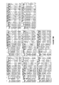
- FIG. 10 shows the beginning portion of a code table for the rate 12/19 (1,18) parity-related constrained code
- FIGS. 11A and 11B show the distribution of candidate code words in various encoder states for a rate 7/16 (1,18) parity-related constrained code
- FIGS. 12A and 12B show examples from the beginning portion of a code table for the rate 7/16 (1,18) parity-related constrained code
- FIG. 13 shows the distribution of candidate code words in various encoder states for a rate 10/20 (2,15) parity-related constrained code
- FIG. 14 shows the beginning portion of a code table for the rate 10/20 (2,15) parity-related constrained code
- FIGS. 15A and 15B show the distribution of candidate code words in various encoder states for a rate 8/22 (2,15) parity-related constrained code
- FIGS. 16A and 16B show examples from the beginning portion of a code table for the rate 8/22 (2,15) parity-related constrained code
- FIG. 17 shows a bit error rate (BER) performance comparison of parity-check coded BD systems with a prior art rate 2/3 (1,7) code and with the newly designed codes, at nominal density;
- FIG. 18 shows a BER performance comparison of parity-check coded BD systems with the prior art rate 2/3 (1,7) code and with the newly designed codes, at high density.
- a sequence of user data which may typically be the binary output of an error correction code (ECC) encoder, is separated into consecutive data blocks, referred to hereafter user data segments. Each user data segment is further partitioned into several data words and then encoded separately.
- ECC error correction code
- parity-related constrained code word All the data words except the last one are encoded by the coding method proposed by Immink et al. (cf. above).
- the obtained code words are referred to as “normal constrained code words”.
- the last data word is, however, encoded by a specific parity-related constrained encoder, and the obtained code word is referred to as the “parity-related constrained code word”. It is designed to realise a certain parity-check constraint over the entire code word, which is a concatenation of the normal constrained code words and the parity-related constrained code word.
- the parity-check constraint to be imposed corresponds to a predetermined parity-check polynomial or parity-check matrix, which is defined to detect dominant error events or error event combinations of a specific data storage system.
- the parity-check polynomial or parity-check matrix needs to be chosen or designed to generate a systematic parity-check code.
- the information bits that satisfy the modulation constraints are used as the code words for both the normal constrained code and the parity-related constrained code, and the parity-check bits are used only for guiding the concatenation of the normal constrained code words and the parity-related constrained code word.
- Both the normal constrained code and the parity-related constrained code are finite-state constrained codes designed based on the same FSM that is proposed by Immink et al. (cf. above), since capacity-approaching codes can thereby be obtained. This also enables the two component codes to be connected seamlessly, without violating the (d, k) constraints.
- For the normal constrained code there is only one code word mapped to each user data word, in each state of the FSM.
- For the parity-related constrained code there is a set of 2 p candidate code words potentially mapped to each user data word, in each state of the FSM, where p is the number of parity-check bits.
- the code word length of the parity-related constrained code has to be longer to achieve the additional parity-check constraint, and hence its rate is smaller.
- the parity-related constrained code is only used as the last code word in the combined code word.
- M is the length of the segment of user data
- N is the length of the combined constrained parity-check code word
- n is the length of the parity-related code word.
- R n and R p are the rates of the normal constrained code and the parity-related constrained code, respectively.
- the choice of the combined code word length N, or the number of consecutive user data segments within a user data sequence, depends on the specific recording system and is a compromise between the code rate loss due to the parity-check and the error correction capability of the post-processor.
- the post-processor can correct both single and double error events that occur within each detected constrained parity-check code word, by using the parity-check result of the detected code word at the output of the channel detector, as well as the channel side information obtained at the input of the channel detector.
- a precoder In the writing path of a data storage system, a precoder, e.g. a modulo-2 integration operation, converts the binary outputs of the constrained encoder into a corresponding modulated signal.
- the modulated signal is further stored on the storage medium.
- the constrained encoded bits before the precoder are referred to as an NRZI sequence, while the precoder output bits are referred to as an NRZ sequence.
- an inverse precoder between the channel detector and the constrained decoder. It converts the detected NRZ sequence back to a NRZI sequence.
- efficient constrained parity-check codes can be designed either in NRZI format or in NRZ format. Corresponding detailed methods are illustrated in the following two embodiments.
- FIG. 1 is a schematic block diagram of encoding apparatus according to a first embodiment of the invention, in the form of a constrained parity-check encoder 10 , which may, for example, operate according to the process illustrated in the flowchart of FIG. 2 .
- an M-bit segment of user data 12 is partitioned into K+1 data words (step S 102 ).
- the K leading data words 14 are individually encoded into first component code words (step S 104 ) by normal constrained encoders 16 .
- K normal constrained code words 14 a are obtained.
- the K+1'th data word 18 is encoded into a second component code word (step S 108 ), which is denoted as the parity-related constrained code word 18 a , by a parity-related constrained encoder 20 .
- a parity-related constrained encoder 20 During encoding the data words into the two component code words 14 a and 18 a , following state information 22 , for instance obtained from a code table stored in a read only memory (ROM) or implemented through a combinatorial logic circuit, is passed from each encoder 16 or 20 to the next encoder 16 or 20 , which is one encoder to the right in FIG. 1 . This state information indicates the next state from which to select a code word for encoding the next data word.
- state information 22 for instance obtained from a code table stored in a read only memory (ROM) or implemented through a combinatorial logic circuit
- the output of the following state information 22 is first stored in a buffer memory 24 .
- the stored state information 22 a at the output of the buffer memory is then passed to the first normal constrained encoder 16 of the encoder 10 while encoding data word 1 of the next data segment.
- the first normal constrained encoder 16 has inputs in the form of the data word 1 of the current data segment, and the state information obtained from the output of the parity-related constrained encoder 20 while encoding the previous data segment.
- the initial following state of the first normal constrained encoder 16 is assumed to be state 1 (S 1 ).
- the encoders 16 and 20 are based on the same FSM, and this encoding process ensures that the (d, k) constraints are satisfied, without introducing further redundant bits between the component code words.
- the apparatus further includes a parity-check unit 26 , which calculates the parity-check bits of the sequence comprising the leading K normal constrained code words (step S 106 ).
- the calculation of the parity-check bits for a given data sequence follows the standard method for encoding linear block codes, as described in S. Lin and D. J. Costello, Error Control Coding Fundamentals and Applications, Prentice-Hall Inc., 1983.
- the obtained parity-check bits 28 are passed to the parity-related encoder 20 , and used to guide encoding the K+1'th data word into the parity-related constrained code word 18 a and to realise a predetermined parity-check constraint over the combined code word.
- the encoder 10 then proceeds with the next data segment of the input user data sequence.
- the concatenation of the obtained N-bit constrained parity-check code words forms the channel encoded data sequence in NRZI format.
- this embodiment uses the FSM proposed by Immink et al. (cf. above), since rates of the constrained codes obtained are very close to the capacity. To achieve a high encoding efficiency, in each state of the FSM one data word is mapped to one code word only. Other FSMs can also be used in conjunction with embodiments of the present invention. However, the obtained code rates may not be as high as that using the FSM proposed by Immink et al. (cf. above).
- this embodiment uses a novel approach, to design sets of candidate code words with various parity-check bits, based on the same FSM of the normal constrained codes.
- the various parity-check bits of the candidate code words correspond to a predetermined parity-check polynomial or parity-check matrix, which is defined to detect dominant error events or error event combinations of a specific system.
- the main steps for the design of the parity-related constrained code in this embodiment are as follows, with reference to FIG. 3 .
- the present embodiment provides a set of criteria that guide the design of the parity-related constrained code. These criteria give clear indications on the choice of size of the code, as well as the number of states in the code table for a given parity-check constraint. They are summarised below.
- the number of candidate code words leaving a state set should be at least 2 m+p times that of the number of states within the state set.
- the candidate code words are divided into S states, which are further classified into two sets of states.
- the first state set has S 1 states, and it includes candidate code words that start with ‘0’.
- the criteria (2) and (3) indicate the smallest length n of the candidate code word that may be obtained for the parity-related constraint code.
- the length n of the candidate code word is further decided by the following criteria.
- the number of candidate code words leaving a state set should be at least 2 m that of the number of states within the state set.
- each candidate code word For each set of the candidate code words with the same parity-check bits, each candidate code word has an assigned following state, which specifies the next state from which to select the code word for the next user data word.
- the same candidate code word that end with a ‘0’ i.e. candidate code words in sets 00 and 10
- the same candidate code word that end with a ‘1’ i.e. candidate code words in sets 01 and 11
- the particular mapping of candidate code word to the data word as defined in the encoder is a matter of design choice, and is not critical to the operation of the system. However, to ensure reliable decoding, different states cannot contain the same candidate code word.
- the candidate code words are divided into S states, which are further classified into three sets of states.
- the first state set has S 1 states, and it includes candidate code words that start only with ‘00’.
- the second state set includes S 2 states, and it includes candidate code words that start with one of ‘10’, ‘01’ or ‘00’.
- the criteria (6), (7) and (8) indicate the smallest length n of the candidate code word that may be obtained for the parity-related constraint code.
- the length n of the candidate code word is further decided by the following criteria that guide the design of each set of candidate code words that has the same parity-check bits:
- the same candidate code word that ends with a ‘00’ i.e. candidate code words in sets 0000 , 1000 and 0100
- the same candidate code word that ends with a ‘10’ i.e. candidate code words in sets 0010 , 1010 , and 0110
- the same candidate code word that ends with a ‘01’ can only be assigned to up to S 1 following states in the first state set and S 3 states in the third state set, and therefore can be used to map to S 1 +S 3 different user data words.
- the same candidate code word that ends with a ‘01’ i.e.
- candidate code words in sets 0001 , 1001 and 0101 can be only assigned to up to S 1 different following states in the first state set, and therefore can be used to map to S 1 different user data words.
- the particular mapping of candidate code word to the data word as defined in the encoder is a matter of design choice, and is not critical to the operation of the system. However, to ensure reliable decoding, different states cannot contain the same candidate code word.
- the first column is the decimal notation of the user data words (i.e. the binary data words 00, 01, 10 and 11 are listed as 0, 1, 2 and 3, respectively).
- Elements in the second to eleventh columns correspond to candidate code words with even parity and the associated following state information.
- the second, fourth, sixth, eighth, and tenth columns are the corresponding candidate code words mapped to the user data words in states 1 to 5, respectively.
- the third, fifth, seventh, ninth, and eleventh columns are the following state information associated with candidate code words in the second, fourth, sixth, eighth, and tenth columns, respectively.
- candidate code words with odd parity and their associated following state information are shown in the twelfth to twenty-first columns.
- FIG. 5 Assuming that the present user data word ( 18 in FIG. 1 ) is ‘11’ (binary—i.e. 3 decimal), all the possible cases that might arise during encoding are listed in FIG. 5 .
- the first two columns illustrate the possible parity-check result ( 28 in FIG. 1 ) of the normal constrained coded sequence, and the following state information 22 associated with the previous code word (code word K in FIG. 1 ), respectively.
- Elements in the third and fourth columns correspond to the obtained current code word (code word 18 a in FIG. 1 ) and the following state information 22 associated with the current code word.
- the combined constrained parity-check code is constructed based on two code tables, i.e. the code table of the normal constrained code and the code table of the parity-related constrained code.
- the normal constrained code words are first constructed and connected. Based on the predetermined parity-check polynomial or parity-check matrix, the parity-check bits of the sequence of the normal constrained code words are computed. After that, the parity-related constrained code word that has the same parity-check bits is selected from the candidate code word sets to concatenate directly with the normal constrained code words. A combined code word satisfying both the modulation constraints and the parity-check constraint is thus constructed.
- the rates of the designed constrained parity-check codes are close to the Shannon capacity, since the two types of component codes are designed based on an efficient FSM, and no additional redundant bits are required to be inserted between the two component code words to sustain the (d, k) constraints. Furthermore, the parity-related constrained code word is also protected by parity-checks, whose parity-check polynomial or parity-check matrix is consistent with that in the sequence of normal constrained code words. This ensures that errors can be corrected equally well over the entire data block. Therefore, error propagation due to the parity-related constrained code word is avoided.
- FIG. 6 illustrates an embodiment of a decoder apparatus in the form of the constrained parity-check decoder 40 for a system for example employing the constrained parity-check encoder 10 described above.
- the decoder 40 performs the reverse process of the encoder 10 and recovers the M-bit segment of user data words 12 from the N-bit constrained parity-check code word 30 a , operating, for example, according to the process illustrated in the flowchart of FIG. 7 .
- the N-bit constrained parity-check code word 30 a is separated into K+1 code words 14 a , 18 a (step S 302 ), which are decoded separately.
- the K normal constrained code words 14 a are decoded by K normal constrained decoders 42 (step S 304 ) into K data words 14 .
- the K+1'th parity-constrained code word 18 a is decoded (step S 306 ) by a parity-related constrained decoder 44 into the K+1'th data word 18 .
- the normal constrained decoders 42 operate as described by Immink et al. (cf. above). Since the normal constrained codes and the parity-related constrained codes are based on the same FSM, the operation of the parity-related constrained decoder 44 in this embodiment is generally the same, but with the associated stored code tables being different.
- the inputs of the normal constrained decoders 42 and the parity-related constrained decoder 44 are both of the current code word and the next code word.
- the decoders 42 , 44 first inspect the next code word, and get its state information through the stored code table. Thereafter, combining this information with the knowledge of the current code word, the decoders 42 , 44 can uniquely determine the user data word associated with the current code word based on the corresponding code table.
- the input following state information is obtained by observing code word K+2 (i.e. code word 1 of the next N-bit code word), and checking the normal constrained code table associated with the code word K+2.
- the decoder 40 needs to inspect one more normal constrained code word of the next N-bit code word. Furthermore, unlike the normal constrained decoders 42 operating based only on one code table of the normal constrained code, the operation of the parity-related constrained decoder 44 is based on two code tables. One code table is the normal constrained code table, which is used to determine the following state of the next code word, while the other code table is the parity-related constrained code table, which is used decode the current code word using the obtained state information of the next code word. In this way, an N-bit constrained parity-check code word is decoded into an M-bit user data segment. The decoder 40 then proceeds with the next N-bit code word in the serial input data, which is referred to as the channel detected data sequences. The similarity in the operation of the two types of decoders 42 and 44 simplifies the hardware implementation.
- the coded bits are all defined in NRZI format.
- the present invention further proposes an approach to design the code in NRZ format. It may be preferable to encode the data in NRZ format due to the following reasons.
- the code table of the normal constrained code can remain the same as that of the normal constrained code in NRZI format.
- the code table for the parity-related constrained code is designed in a different way. The detailed procedures are as follows.
- the order of code word sets with the same parity-check bits may need to be adjusted according to the different initial NRZ bits.
- the criteria that guide the design of the parity-related constrained codes in NRZ format are the same as those guiding the design of the NRZI format codes, the only difference being that the parity-check bits of the candidate code words are computed in the NRZ domain, rather than in the NRZI domain.
- FIG. 8 illustrates a schematic block diagram of an encoder 50 for encoding the constrained parity-check code in the NRZ format.
- an M-bit segment of user data 12 is partitioned into K+1 data words.
- the K leading data words 14 are individually encoded by normal constrained encoders 16 .
- K normal constrained code words 14 a are obtained.
- the K+1'th data word 18 is encoded by a parity-related constrained encoder 52 , which outputs a parity-related constrained code word 54 (which is different from the parity-related constrained code word ( 18 a in FIG. 1 ) produced by the encoder of the first embodiment).
- following state information 22 is passed from each encoder 16 , 52 to the next encoder 16 , 52 .
- This state information 22 indicates the next state from which to select a code word for encoding the next data word.
- the output of the following state information 22 is first stored in a buffer memory 56 .
- the stored state information 22 a at the output of the buffer memory is then passed to the first normal constrained encoder 16 of the encoder 50 while encoding data word 1 of the next data segment.
- the first normal constrained encoder 16 has as its inputs the data word 1 of the current data segment, and the state information obtained from the output of parity-related constrained encoder 52 while encoding the previous data segment.
- the initial following state of the first normal constrained encoder 16 is assumed to be state 1 (S 1 ).
- the encoders 16 , 52 are based on the same FSM, and this encoding process ensures that the (d, k) constraints are satisfied, without introducing further redundant bits between the two component code words.
- the user data words 14 associated with the leading K normal constrained codes are first encoded in NRZI format.
- the resulting constrained code words 14 a are then converted into NRZ format through a first precoder 58 , to produce precoded constrained code words 14 b .
- the parity-check bits 60 of the sequence comprising the leading K precoded normal constrained code words are computed through a parity-check unit 24 , which is the same as that in FIG. 1 .
- the first precoder 58 also outputs the last NRZ bit 62 of the K'th precoded normal constrained code word.
- the parity-related constrained encoder 52 Based on these NRZ parity-check bits 60 as well as the last NRZ bit 62 of the K'th precoded code word, the parity-related constrained encoder 52 assigns its candidate code word in NRZI format that has the same NRZ parity-check bits to the K+1'th data word 18 .
- the obtained parity-related constrained code word 54 needs to be converted into NRZ format through a second precoder 64 , before concatenating with the normal constrained code words 14 b in NRZ format. In this way an N-bit constrained parity-check code word 30 b in NRZ format are obtained.
- the second precoder 64 not only outputs the precoded K+1'th code word 18 b , but also the last NRZ bit 66 of that precoded K+1'th code word.
- This last NRZ bit 66 is first stored in a buffer memory 68 .
- the stored last NRZ bit 66 a at the output of the buffer memory 68 is then passed to the first precoder 58 of the encoder 50 , and is used to encode the next data segment.
- the first precoder 58 has as its inputs the normal constrained code words 14 a and the last NRZ bit 66 a of the precoded K+1'th code word from the previous data segment.
- the initial NRZ bit for the first precoder 58 is assumed to be ‘ ⁇ 1’.
- the subsequent user data segments within the input user data sequence are encoded by the encoder 50 one by one, and the concatenation of the obtained N-bit constrained parity-check code words forms the channel encoded data sequence in NRZ format.
- the detected NRZ data sequence is first converted into NRZI format through an inverse precoder, and the resulting NRZI sequence is then decoded based on the code tables of the normal constrained code and the parity-related constrained code, along the same lines as in the foregoing detailed description and as shown in FIGS. 6 and 7 .
- the user data is encoded and decoded one segment at a time, with encoding occurring in the original order of the data, and decoding in the original order or the reverse order.
- the encoding may be in reverse order and the decoding then in the reverse order or the correct order.
- the above embodiments use following state information produced by the last component code encoder while encoding the previous data segment for encoding the first data word of the current data segment.
- the initial input following state information for encoding the first data word of the first data segment is assumed to be state 1 (S 1 ).
- the above embodiments use the first component code word of the next constrained parity-check code word for decoding the last component code word of the current constrained parity-check code word.
- the following state information at the beginning and end of each segment is obtained from the adjacent segment, in both encoding and decoding.
- the initial following state information may be derived from non-adjacent segments, e.g. from a segment two away.
- the same first segment used to provide following state information to a second segment in encoding should generally be provided with the following state information from the same second segment in decoding.
- a new (1,18) constrained single-bit even parity-check code can be designed.
- the rate 12/19 (1,18) code achieves 1 channel bits per parity-check.
- states 1, 2, and 3 are sub-states in the first state set, which includes candidate code words that start with ‘0’ (i.e. candidate code words in sets 00 and 01 ) only.
- States 4 and 5 are sub-states in the second state set, which includes candidate code words that start either with ‘0’ or ‘1’ (i.e. candidate code words in sets 00 , 01 , 10 , 11 ).
- the candidate code words are distributed according to the restrictions that the same code word ending with a ‘0’ (i.e.
- different states cannot contain the same candidate code word.
- the set 00 has 605 candidate code words allocated in State 1, 599 candidate code words in state 2, and 603 candidate code words in state 3.
- 12-bit user data words can be encoded.
- candidate code words having odd parity with an assumed initial NRZ bit of ‘ ⁇ 1’ (or even parity with an assumed initial NRZ bit of ‘+1’) are distributed as shown in the second table in FIG. 9 .
- This table also shows that 12-bit user data words can be supported.
- a rate 12/19 (1,18) parity-related constrained code can be constructed.
- FIG. 10 shows the beginning portion of the code table for the rate 12/19 (1,18) parity-related constrained code.
- the first column is the decimal notation of the user data words.
- Elements in the second to eleventh columns correspond to the decimal notation of the candidate code words having even parity with an assumed initial NRZ bit of ‘ ⁇ 1’ (or odd parity with an assumed initial NRZ bit of ‘+1’), and the associated following state information.
- the second, fourth, sixth, eighth, and tenth columns are the corresponding candidate code words mapped to the user data words in states 1 to 5, respectively.
- the third, fifth, seventh, ninth, and eleventh columns are the following state information associated with candidate code words in the second, fourth, sixth, eighth, and tenth columns, respectively.
- candidate code words having odd parity with an assumed initial NRZ bit of ‘ ⁇ 1’ (or even parity with an assumed initial NRZ bit of ‘+1’) and their associated following state information are shown in the twelfth to twenty-first columns.
- FIGS. 12A and 12B are examples from the beginning portion of the code table for the rate 7/16 (1,18) parity-related constrained code, in the same manner that FIG. 10 illustrated the code table for the 12/19 code.
- FIGS. 12A and 12B illustrate the first two of these and the last two, respectively.
- the rate 8/15 (2,10) EFM-like code the rate 10/20 (2,15) code achieves 1.25 channel bits per parity-check, and the 8/22 (2,15) code achieves 1.75 channel bits per parity-check.
- the total numbers of candidate code words in the candidate code word sets 0000 , 0010 , 0001 , 1000 , 1010 , 1001 , 0100 , 0110 , and 0101 are illustrated in the third row of the second to tenth columns, respectively.
- states 1, 2, 3, and 4 are sub-states in the first state set, which includes candidate code words that start with ‘00’.
- States 5, 6 and 7 are sub-states in the second state set, which includes candidate code words that start either with one of ‘10’, ‘01’ and ‘00’.
- States 8 and 9 are sub-states in the third state set, which includes candidate code words that start either with ‘01’ or ‘00’.
- the same candidate code word that end with a ‘10’ i.e. candidate code words in sets 0010 , 1010 , and 0110
- S 1 +S 3 6 different user data words.
- different states cannot contain the same candidate code word.
- the set 0000 has 70 candidate code words allocated in State 1, 71 candidate code words in states 2 and 3, 72 candidate code words in state 4, 8 candidate code words in state 7, and 3 candidate code words in state 9.
- 10-bit user data words can be encoded.
- candidate code words having odd parity with an assumed initial NRZ bit of either ‘ ⁇ 1’ or ‘+1’ are distributed as shown in the second table in FIG. 13 .
- This table also shows that 10-bit input data words can be supported. Following the tables shown in FIG. 13 , a rate 10/20 (2,15) parity-related constrained code can be constructed.
- FIG. 14 shows the beginning portion of the code table for the rate 10/20 (2,15) parity-related constrained code.
- the first column is the decimal notation of the user data words.
- Elements in the second to nineteenth columns correspond to the decimal notation of the candidate code words having even parity with an assumed initial NRZ bit of either ‘ ⁇ 1’ or ‘+1’, and the associated following state information.
- the second, fourth, sixth, eighth, tenth, twelfth, fourteenth, sixteenth and eighteenth columns are the corresponding candidate code words mapped to the user data words in states 1 to 9, respectively.
- the third, fifth, seventh, ninth, eleventh, thirteenth, fifteenth, seventeenth and nineteenth columns are the following state information associated with candidate code words in the second, fourth, sixth, eighth, tenth, twelfth, fourteenth, sixteenth and eighteenth columns, respectively.
- candidate code words having odd parity with an assumed initial NRZ bit of either ‘ ⁇ 1’ or ‘+1’ and their associated following state information are shown in the twentieth to thirty-seventh columns.
- there are 16 distribution tables illustrated in FIGS. 15A and 15B corresponding to the various parity-check bits of the candidate code words.
- FIGS. 16A and 16B are examples from the beginning portion of the code table for the rate 8/22 (2,15) parity-related constrained code, in the same manner that FIG. 14 illustrated the code table for the 10/20 code.
- FIGS. 16A and 16B illustrate the first two of these and the last two, respectively.
- ⁇ u f c T u , where f c is the optical cut-off frequency, and T u is the duration of one user bit, is a measure of the recording density. The smaller ⁇ u is, the higher is the recording density, and vice versa.
- the sampled sequence is supplied to a channel detector such as a Viterbi detector.
- the channel noise before equalization is assumed to be Gaussian and white.
- the dominant error events at the Viterbi detector output turn out to be ⁇ 2 ⁇ , ⁇ 2, 0, ⁇ 2 ⁇ 2, 0, ⁇ 2,0,2 ⁇ , and ⁇ 2, 0, ⁇ 2, 0, 2, 0, ⁇ 2 ⁇ .
- the error event is the difference between the transmitted data sequence and the detected data sequence at the channel detector output.
- a post-processor is adopted for error correction. It can correct both single and double error events that occur within each detected constrained parity-check code word, by using the parity-check result of the detected code word at the output of the Viterbi detector, as well as the channel side information obtained at the input of the Viterbi detector.
- FIGS. 17 and 18 illustrate the bit error rate (BER) performance comparison of the parity-check coded BD systems with the conventional rate 2/3 (1,7) code and with the newly designed codes, at nominal density and high density, respectively.
- BER bit error rate
- the parity-check codes are modelled by assuming that the parity-check for each detected code word is known at the detector side. This is done by generating a syndrome component for each detected code word in a ‘data-aided’ mode.
- the performance of the rate 9/13 (1,18) code without parity-check is illustrated by Curve 4 .
- the performances of the new constrained single-bit even parity-check code and the new constrained 4-bit parity-check code are illustrated by Curves 5 and 6 , respectively.
- the code word length of both the single-bit even parity-check codes is chosen to be 97, since it achieves a trade-off between code rate loss due to parity-check and error correction power of the post-processor.
- the overall code rate of the new constrained single-bit event parity-check code, according to equation (1), is thus 0.6804.
- the rate 9/13 code brings significant performance gain over the conventional rate 2/3 code, for both cases without and with the parity-check code, due to its higher code rate.
- the new 4-bit constrained parity-check codes gain around 0.7 dB over the rate 2/3 code with ideal 4-bit parity-check at nominal density.
- the performance improvement is around 1 dB.
- the new 4-bit constrained parity-check code achieves a performance gain of 2 dB at nominal density, and 1.5 dB gain at high density.
- the above-described exemplary embodiments are able to encode a segment of user data into a segment of channel code words so that both modulation constraints and a predetermined parity-check constraint are satisfied.
- Each segment of the user data is partitioned into several data words, and encoded separately by first and second types of component code, which are referred to as the normal constrained code and the parity-related constrained code, respectively.
- the parity-check constraint over the combined code word is achieved by concatenating the sequence of normal constrained code words with a specific parity-related constrained code word chosen from a candidate code word set.
- Both the component codes are finite-state constrained codes, which are designed to have the rates close to the Shannon capacity.
- Two preferred embodiments are provided to design the code in the NRZI format and the NRZ format, respectively. Designing the codes in NRZ format may reduce the number of parity-check bits required for error detection and simplify error correction or post-processing.
- the parity-check constraint is defined by the parity-check polynomial or parity-check matrix of a systematic linear block code, which could detect any type of dominant error event as well as error events combinations of a given optical recording system. As a result, the information density of the system is improved.
- encoders and decoders described above may be implemented using just hardware, with circuits dedicated for the required processing, or by a combination of hardware and software modules.
- a module and in particular the module's functionality, can be implemented in either hardware or software.
- a module is a process, program, or portion thereof, that usually performs a particular function or related functions.
- a module is a functional hardware unit designed for use with other components or modules.
- a module may be implemented using discrete electronic components, or it can form a portion of an entire electronic circuit such as an Application Specific Integrated Circuit (ASIC). Numerous other possibilities exist.
- ASIC Application Specific Integrated Circuit
Landscapes
- Engineering & Computer Science (AREA)
- Theoretical Computer Science (AREA)
- Physics & Mathematics (AREA)
- Probability & Statistics with Applications (AREA)
- Signal Processing (AREA)
- Error Detection And Correction (AREA)
- Signal Processing For Digital Recording And Reproducing (AREA)
- Detection And Correction Of Errors (AREA)
Abstract
Description
where M is the length of the segment of user data, N is the length of the combined constrained parity-check code word, and n is the length of the parity-related code word.
- (1) First release the k constraint (e.g. larger than k=7 for d=1 codes, and larger than k=10 for d=2 codes) (step S202) and design candidate code words of the parity-related constrained code (step S204) (e.g. using the FSM proposed by Immink et al. [cf. above], and following a set of criteria described below), to achieve a capacity approaching code rate. The candidate code words are constructed based on the same FSM with the normal constrained code. For the same length of user data, the length of a parity-related constrained code word needs to be longer than that of the normal constrained code word in order to achieve a specific parity-check constraint.
- (2) Based on the given parity-check polynomial or parity-check matrix, and taking into account the length of the sequence comprising the normal constrained code words, compute the parity-check bits (step S206) of the candidate code words obtained from Step (1) and distribute them (step S208) into a group of code word sets. A total of 2p code word sets are obtained.
- (3) Concatenate the 2p code word sets together (step S210), and form a code table (step S212) for encoding/decoding of the parity-related constrained code. Compared with the code table of the normal constrained code, the code table designed for the parity-related constrained code is enlarged by a factor of 2p. In each state of the FSM, there is a set of 2p candidate code words potentially mapped to one user data word. During encoding, as illustrated in
FIG. 1 , the parity-check bits of the sequence of the normal constrained code words are first calculated, and the parity-related code word having the same parity-check bits is selected from the candidate code word set and assigned to the user data word. - (4) Tighten the k constraint of the candidate code words (step S214) in the table obtained from step (3), towards the original k, by optimising the code table through deleting code words that start or end with long runs of ‘0’s, or by increasing the number of states in the FSM.
S|C 00 |+S 1 |C 01 ≧S 12m+p, (2)
S(|C 00 |+|C 10|)+S 1(|C 01 |+|C 11|)≧S 2 m+p, (3)
where C00 denotes the set of candidate code words that start and end with a ‘0’, C01 denotes the set of candidate code words that start with a ‘0’ and end with a ‘1’, C10 denotes the set of candidate code words that start with a ‘1’ and end with a ‘0’, and C11 denotes the set of candidate code words that start and end with a ‘1’. Here, |Cxy| denotes the size of Cxy.
S|
S(|
where
where the two leading symbols of the subscript of the candidate code word set C denote the leading two bits of the candidate code words, while the two trailing symbols of the subscript denote the trailing two bits of the candidate code words. Here, |Cxyzw| denotes the size of Cxyzw.
where
where Ω is the frequency normalised by the channel bit rate, and R is the rate of the d=1 constrained parity-check code. The quantity Ωu=fcTu, where fc is the optical cut-off frequency, and Tu is the duration of one user bit, is a measure of the recording density. The smaller Ωu is, the higher is the recording density, and vice versa. For an optical recording system using a laser diode with wavelength λ and a lens with numerical aperture NA, the normalised cut-off frequency is given Ωu=2 NA Lu/λ, where Lu is the spatial length of one user bit. For BD systems using the
Claims (81)
R=R n−(n/N)(R n −R p),
Applications Claiming Priority (1)
| Application Number | Priority Date | Filing Date | Title |
|---|---|---|---|
| PCT/SG2004/000357 WO2006046925A1 (en) | 2004-10-26 | 2004-10-26 | Method and system for encoding and decoding information with modulation constraints and error control |
Publications (2)
| Publication Number | Publication Date |
|---|---|
| US20080141095A1 US20080141095A1 (en) | 2008-06-12 |
| US8078935B2 true US8078935B2 (en) | 2011-12-13 |
Family
ID=36228086
Family Applications (1)
| Application Number | Title | Priority Date | Filing Date |
|---|---|---|---|
| US11/796,094 Expired - Fee Related US8078935B2 (en) | 2004-10-26 | 2004-10-26 | Method and system for encoding and decoding information with modulation constraints and error control |
Country Status (4)
| Country | Link |
|---|---|
| US (1) | US8078935B2 (en) |
| JP (1) | JP5011116B2 (en) |
| TW (1) | TW200636442A (en) |
| WO (1) | WO2006046925A1 (en) |
Cited By (4)
| Publication number | Priority date | Publication date | Assignee | Title |
|---|---|---|---|---|
| US20110041653A1 (en) * | 2007-12-12 | 2011-02-24 | Joo Hyun Park | Method of manufacturing ultra low carbon ferritic stainless steel |
| KR101268061B1 (en) | 2011-10-21 | 2013-05-28 | 단국대학교 산학협력단 | Encoing and decoding method using multiple state accumulate code |
| US11695429B2 (en) | 2021-07-29 | 2023-07-04 | Samsung Display Co., Ltd. | Systems and methods for transition encoding with protected key |
| US12081376B2 (en) | 2021-11-05 | 2024-09-03 | Samsung Display Co., Ltd. | DC balanced transition encoding |
Families Citing this family (10)
| Publication number | Priority date | Publication date | Assignee | Title |
|---|---|---|---|---|
| EP1966895A2 (en) * | 2005-12-19 | 2008-09-10 | Koninklijke Philips Electronics N.V. | A coder and a method of coding for codes with a parity-complementary word assignment having a constraint of d=1, r=2 |
| JP5228047B2 (en) | 2007-08-14 | 2013-07-03 | エルジー エレクトロニクス インコーポレイティド | Data transmission method |
| US9431053B2 (en) * | 2014-04-24 | 2016-08-30 | Marvell International Ltd. | Run-length limited (RLL) codes |
| US10771189B2 (en) | 2018-12-18 | 2020-09-08 | Intel Corporation | Forward error correction mechanism for data transmission across multi-lane links |
| CN109753369B (en) * | 2018-12-28 | 2023-10-24 | 上海微阱电子科技有限公司 | Data coding and checking method for sequence array in register and memory |
| US11637657B2 (en) * | 2019-02-15 | 2023-04-25 | Intel Corporation | Low-latency forward error correction for high-speed serial links |
| US11249837B2 (en) | 2019-03-01 | 2022-02-15 | Intel Corporation | Flit-based parallel-forward error correction and parity |
| US11296994B2 (en) | 2019-05-13 | 2022-04-05 | Intel Corporation | Ordered sets for high-speed interconnects |
| US11740958B2 (en) | 2019-11-27 | 2023-08-29 | Intel Corporation | Multi-protocol support on common physical layer |
| US12189470B2 (en) | 2020-09-18 | 2025-01-07 | Intel Corporation | Forward error correction and cyclic redundancy check mechanisms for latency-critical coherency and memory interconnects |
Citations (7)
| Publication number | Priority date | Publication date | Assignee | Title |
|---|---|---|---|---|
| JP2001189059A (en) | 1999-12-28 | 2001-07-10 | Nec Corp | Recording/reproducing device |
| WO2002080373A1 (en) | 2001-03-30 | 2002-10-10 | Koninklijke Philips Electronics N.V. | Methods and devices for converting as well as decoding a stream of data bits, signal and record carrier |
| US20030072242A1 (en) | 2001-10-15 | 2003-04-17 | Fujitsu Limited | Data recording apparatus, data reproducing apparatus, and data recording/reproducing apparatus |
| US6606038B2 (en) | 2000-06-22 | 2003-08-12 | Lg Electronics Inc. | Method and apparatus of converting a series of data words into modulated signals |
| US6639524B2 (en) | 2000-03-22 | 2003-10-28 | Lg Electronics Inc. | Method and apparatus for coding information, method and apparatus for decoding coded information, method of fabricating a recording medium, the recording medium and modulated signal |
| US20050166130A1 (en) * | 2002-04-18 | 2005-07-28 | Koninklijke Philips Electronics N.V. | Signal, storage medium, method and device for encoding, method and device for decoding |
| US20050171973A1 (en) * | 2002-04-26 | 2005-08-04 | Koninkljke Philips Electronics N.V. | Method and apparatus for multi-dimensionally encoding and decoding |
Family Cites Families (3)
| Publication number | Priority date | Publication date | Assignee | Title |
|---|---|---|---|---|
| KR100472524B1 (en) * | 1999-06-30 | 2005-03-09 | 시게이트 테크놀로지 엘엘씨 | Partial response channel having combined mtr and parity constraints |
| US6505320B1 (en) * | 2000-03-09 | 2003-01-07 | Cirrus Logic, Incorporated | Multiple-rate channel ENDEC in a commuted read/write channel for disk storage systems |
| KR20050097924A (en) * | 2002-12-30 | 2005-10-10 | 코닌클리케 필립스 일렉트로닉스 엔.브이. | Coding system |
-
2004
- 2004-10-26 JP JP2007538867A patent/JP5011116B2/en not_active Expired - Fee Related
- 2004-10-26 US US11/796,094 patent/US8078935B2/en not_active Expired - Fee Related
- 2004-10-26 WO PCT/SG2004/000357 patent/WO2006046925A1/en active Application Filing
-
2005
- 2005-10-25 TW TW094137323A patent/TW200636442A/en unknown
Patent Citations (10)
| Publication number | Priority date | Publication date | Assignee | Title |
|---|---|---|---|---|
| JP2001189059A (en) | 1999-12-28 | 2001-07-10 | Nec Corp | Recording/reproducing device |
| US6639524B2 (en) | 2000-03-22 | 2003-10-28 | Lg Electronics Inc. | Method and apparatus for coding information, method and apparatus for decoding coded information, method of fabricating a recording medium, the recording medium and modulated signal |
| US6606038B2 (en) | 2000-06-22 | 2003-08-12 | Lg Electronics Inc. | Method and apparatus of converting a series of data words into modulated signals |
| WO2002080373A1 (en) | 2001-03-30 | 2002-10-10 | Koninklijke Philips Electronics N.V. | Methods and devices for converting as well as decoding a stream of data bits, signal and record carrier |
| US20030028839A1 (en) | 2001-03-30 | 2003-02-06 | Coene Willem Marie Julia Marcel | Methods and devices for converting as well as decoding a stream of data bits, signal and record carrier |
| JP2004532561A (en) | 2001-03-30 | 2004-10-21 | コーニンクレッカ フィリップス エレクトロニクス エヌ ヴィ | Method and apparatus for decoding and converting a data bit stream and signal and record carrier |
| US20030072242A1 (en) | 2001-10-15 | 2003-04-17 | Fujitsu Limited | Data recording apparatus, data reproducing apparatus, and data recording/reproducing apparatus |
| JP2003123400A (en) | 2001-10-15 | 2003-04-25 | Fujitsu Ltd | Data recording device, data reproducing device and data recording / reproducing device |
| US20050166130A1 (en) * | 2002-04-18 | 2005-07-28 | Koninklijke Philips Electronics N.V. | Signal, storage medium, method and device for encoding, method and device for decoding |
| US20050171973A1 (en) * | 2002-04-26 | 2005-08-04 | Koninkljke Philips Electronics N.V. | Method and apparatus for multi-dimensionally encoding and decoding |
Non-Patent Citations (14)
| Title |
|---|
| A. Patapoutian, B.Z. Shen, and P.A. McEwen, "Event Error Control Codes and Their Applications," IEEE Trans. Inform. Theory, vol. 47, No. 6, pp. 2595-2603, Sep. 2001. |
| H. Sawaguchi, S. Mita, and J.K. Wolf, "A concatenated coding technique for partial response channels," IEEE Trans. Magnetics, vol. 37, No. 2, pp. 695-703, Mar. 2001. |
| H. Song, B.V.K. Vijaya Kumar, E. Kurtas, Y. Yuan, L.L. Mc Pheters, and S.W. McLaughlin, "Iterative decoding for partial response (PR) equalized magneto-optical (MO) data storage channels," IEEE, Journal of Selected Area on Communications, vol. 19, pp. 774-883, 2001. |
| Japanese Office Action dated Aug. 2, 2011, from Application No. 2007-538867. |
| Japanese Office Action dated Oct. 26, 2010, from Application No. 2007-538867. |
| K. Cai, V.Y. Krachkovsky, and J.W.M. Bergmans, "Performance bounds for parity coded optical recoding channels with d=1 constraint," Proc. of IEEE International Conference on Communications (ICC), Alaska, USA, May 2003. |
| K.A.S. Immink, J.K. Kim, and S.W. Suh, "Efficient Dc-free RLL codes for Optical Recording," IEEE Trans. Commun., vol. 51, pp. 326-331, Mar. 2003. |
| Korean Office action dated Feb. 18, 2011, from Application No. 10-2007-7011934. |
| L.L. McPheters and S.W. McLaughlin, "Turbo-coded optical recording channels with DVD minimum mark size," IEEE Trans. Magnetics, vol. 38, No. 1, pp. 298-302, Jan. 2002. |
| P. Perry, M.C. Lin, and Z. Zhang, "Runlength-Limited Codes for Single Error-Detection and Single Error-Correction with Mixed Type Errors, "IEEE Trans. Inform. Theory, vol. 44, No. 4, pp. 1588-1592, Jul. 1998. |
| S. Gopalaswamy and J.W.M. Bergmans, "Modified target and concatenated Coding for constrained magnetic recording channels," in Proc. IEEE Intl. Conf. Commun. (ICC), New Orleans, USA, Jun. 2000, pp. 89-93. |
| T. Nakagawa, H. Ino, and Y. Shimpuku, "A simple detection method for RLL codes (Run detector)," IEEE Trans. Magnetics, vol. 33, No. 5, pp. 3262-3264, Sep. 1997. |
| T. Narahara, S. Kobayashi, Y. Shimpuku, G. van den Enden, J. Kahlman, M. van Dijk, and R. van Woudenburg, "Optical disc system for digital video recording," Jpn. J. Appl. Phys., pt. 1, vol. 39, No. 2B, pp. 912-919, 2000. |
| W. Coene, H. Pozidis, J. Bergmans, "Run-length limited parity-check coding for transition-shift errors in optical recording," in Proc. IEEE Intl. Conf. Global Telecommun. (GLOBECOM), San Antonio, Nov. 2001, pp. 2982-2986. |
Cited By (5)
| Publication number | Priority date | Publication date | Assignee | Title |
|---|---|---|---|---|
| US20110041653A1 (en) * | 2007-12-12 | 2011-02-24 | Joo Hyun Park | Method of manufacturing ultra low carbon ferritic stainless steel |
| KR101268061B1 (en) | 2011-10-21 | 2013-05-28 | 단국대학교 산학협력단 | Encoing and decoding method using multiple state accumulate code |
| US11695429B2 (en) | 2021-07-29 | 2023-07-04 | Samsung Display Co., Ltd. | Systems and methods for transition encoding with protected key |
| US12015423B2 (en) | 2021-07-29 | 2024-06-18 | Samsung Display Co., Ltd. | Systems and methods for decoding transition encoded data with protected key |
| US12081376B2 (en) | 2021-11-05 | 2024-09-03 | Samsung Display Co., Ltd. | DC balanced transition encoding |
Also Published As
| Publication number | Publication date |
|---|---|
| JP5011116B2 (en) | 2012-08-29 |
| WO2006046925A1 (en) | 2006-05-04 |
| TW200636442A (en) | 2006-10-16 |
| US20080141095A1 (en) | 2008-06-12 |
| JP2008518381A (en) | 2008-05-29 |
Similar Documents
| Publication | Publication Date | Title |
|---|---|---|
| KR101244580B1 (en) | A coder and a method of coding for codes with a parity-complementary word assignment having a constraint of D=1,R=2 | |
| KR101114057B1 (en) | Rll encoding | |
| JP3477106B2 (en) | Apparatus and method for rate 16/17 (0,5) modulation code for partial response magnetic recording channel | |
| US8078935B2 (en) | Method and system for encoding and decoding information with modulation constraints and error control | |
| US20090027239A1 (en) | Coder and a method of coding for codes having a repeated maximum transition run constraint of 2 | |
| US20050220197A1 (en) | Coding method and decoding method | |
| KR101211244B1 (en) | Modulation coding and decoding | |
| US7616134B1 (en) | Systems and methods for enumerative encoding and decoding of maximum-transition-run codes and PRML (G,I,M) codes | |
| US6347390B1 (en) | Data encoding method and device, data decoding method and device, and data supply medium | |
| US6204781B1 (en) | General rate N/(N+1) (0, G) code construction for data coding | |
| KR19980031982A (en) | PRML code generation method of data storage device | |
| JP3837742B2 (en) | Decoding device and decoding method, recording / reproducing device, program storage medium, and program | |
| US20030028839A1 (en) | Methods and devices for converting as well as decoding a stream of data bits, signal and record carrier | |
| US6097321A (en) | Punctured maximum transition run code, apparatus and method for providing the same | |
| Cai et al. | A general construction of constrained parity-check codes for optical recording | |
| US7203884B2 (en) | Shaped spectral coding and recording systems therefor | |
| Coene et al. | Run-length limited parity-check coding for transition-shift errors in optical recording | |
| Cai et al. | On the design of efficient constrained parity-check codes for optical recording | |
| KR20070074640A (en) | Method and system for encoding and decoding information with modulation constraints and error control | |
| JP2005141887A (en) | Decoding device and method, recording and reproducing device and method, program recording medium, and program | |
| Cai et al. | Distance-Enhancing Constrained Codes for Optical Recording Channels | |
| Cai et al. | Performance bounds for parity coded optical recording channels with d= 1 constraint | |
| Cai et al. | Novel constrained parity-check code and post-processor for advanced blue laser disk | |
| Cai et al. | Distance-enhancing constrained codes with parity-check constraints for data storage channels | |
| Cai et al. | The Art of Combining Distance-Enhancing Constrained Codes with Parity-Check Codes for Data Storage Channels |
Legal Events
| Date | Code | Title | Description |
|---|---|---|---|
| AS | Assignment |
Owner name: AGENCY FOR SCIENCE, TECHNOLOGY AND RESEARCH, SINGA Free format text: ASSIGNMENT OF ASSIGNORS INTEREST;ASSIGNORS:CAI, KUI;IMMINK, KEES A. SCHOUHAMER;REEL/FRAME:019255/0465;SIGNING DATES FROM 20041207 TO 20041212 Owner name: AGENCY FOR SCIENCE, TECHNOLOGY AND RESEARCH, SINGA Free format text: ASSIGNMENT OF ASSIGNORS INTEREST;ASSIGNORS:CAI, KUI;IMMINK, KEES A. SCHOUHAMER;SIGNING DATES FROM 20041207 TO 20041212;REEL/FRAME:019255/0465 |
|
| REMI | Maintenance fee reminder mailed | ||
| LAPS | Lapse for failure to pay maintenance fees | ||
| STCH | Information on status: patent discontinuation |
Free format text: PATENT EXPIRED DUE TO NONPAYMENT OF MAINTENANCE FEES UNDER 37 CFR 1.362 |
|
| FP | Lapsed due to failure to pay maintenance fee |
Effective date: 20151213 |