US8076894B2 - Superconductive rotating electric machine drive control system and superconductive rotating electric machine drive control method - Google Patents
Superconductive rotating electric machine drive control system and superconductive rotating electric machine drive control method Download PDFInfo
- Publication number
- US8076894B2 US8076894B2 US12/513,386 US51338607A US8076894B2 US 8076894 B2 US8076894 B2 US 8076894B2 US 51338607 A US51338607 A US 51338607A US 8076894 B2 US8076894 B2 US 8076894B2
- Authority
- US
- United States
- Prior art keywords
- electric machine
- superconductive
- rotating electric
- power
- synchronous rotating
- Prior art date
- Legal status (The legal status is an assumption and is not a legal conclusion. Google has not performed a legal analysis and makes no representation as to the accuracy of the status listed.)
- Expired - Fee Related, expires
Links
Images


Classifications
-
- B—PERFORMING OPERATIONS; TRANSPORTING
- B63—SHIPS OR OTHER WATERBORNE VESSELS; RELATED EQUIPMENT
- B63H—MARINE PROPULSION OR STEERING
- B63H21/00—Use of propulsion power plant or units on vessels
- B63H21/12—Use of propulsion power plant or units on vessels the vessels being motor-driven
- B63H21/17—Use of propulsion power plant or units on vessels the vessels being motor-driven by electric motor
-
- H—ELECTRICITY
- H02—GENERATION; CONVERSION OR DISTRIBUTION OF ELECTRIC POWER
- H02P—CONTROL OR REGULATION OF ELECTRIC MOTORS, ELECTRIC GENERATORS OR DYNAMO-ELECTRIC CONVERTERS; CONTROLLING TRANSFORMERS, REACTORS OR CHOKE COILS
- H02P23/00—Arrangements or methods for the control of AC motors characterised by a control method other than vector control
- H02P23/0004—Control strategies in general, e.g. linear type, e.g. P, PI, PID, using robust control
-
- H—ELECTRICITY
- H02—GENERATION; CONVERSION OR DISTRIBUTION OF ELECTRIC POWER
- H02P—CONTROL OR REGULATION OF ELECTRIC MOTORS, ELECTRIC GENERATORS OR DYNAMO-ELECTRIC CONVERTERS; CONTROLLING TRANSFORMERS, REACTORS OR CHOKE COILS
- H02P9/00—Arrangements for controlling electric generators for the purpose of obtaining a desired output
- H02P9/14—Arrangements for controlling electric generators for the purpose of obtaining a desired output by variation of field
-
- B—PERFORMING OPERATIONS; TRANSPORTING
- B63—SHIPS OR OTHER WATERBORNE VESSELS; RELATED EQUIPMENT
- B63H—MARINE PROPULSION OR STEERING
- B63H21/00—Use of propulsion power plant or units on vessels
- B63H21/12—Use of propulsion power plant or units on vessels the vessels being motor-driven
- B63H21/17—Use of propulsion power plant or units on vessels the vessels being motor-driven by electric motor
- B63H2021/173—Use of propulsion power plant or units on vessels the vessels being motor-driven by electric motor making use of superconductivity
-
- H—ELECTRICITY
- H02—GENERATION; CONVERSION OR DISTRIBUTION OF ELECTRIC POWER
- H02P—CONTROL OR REGULATION OF ELECTRIC MOTORS, ELECTRIC GENERATORS OR DYNAMO-ELECTRIC CONVERTERS; CONTROLLING TRANSFORMERS, REACTORS OR CHOKE COILS
- H02P2101/00—Special adaptation of control arrangements for generators
- H02P2101/45—Special adaptation of control arrangements for generators for motor vehicles, e.g. car alternators
-
- H—ELECTRICITY
- H02—GENERATION; CONVERSION OR DISTRIBUTION OF ELECTRIC POWER
- H02P—CONTROL OR REGULATION OF ELECTRIC MOTORS, ELECTRIC GENERATORS OR DYNAMO-ELECTRIC CONVERTERS; CONTROLLING TRANSFORMERS, REACTORS OR CHOKE COILS
- H02P2207/00—Indexing scheme relating to controlling arrangements characterised by the type of motor
- H02P2207/05—Synchronous machines, e.g. with permanent magnets or DC excitation
-
- Y—GENERAL TAGGING OF NEW TECHNOLOGICAL DEVELOPMENTS; GENERAL TAGGING OF CROSS-SECTIONAL TECHNOLOGIES SPANNING OVER SEVERAL SECTIONS OF THE IPC; TECHNICAL SUBJECTS COVERED BY FORMER USPC CROSS-REFERENCE ART COLLECTIONS [XRACs] AND DIGESTS
- Y02—TECHNOLOGIES OR APPLICATIONS FOR MITIGATION OR ADAPTATION AGAINST CLIMATE CHANGE
- Y02T—CLIMATE CHANGE MITIGATION TECHNOLOGIES RELATED TO TRANSPORTATION
- Y02T70/00—Maritime or waterways transport
- Y02T70/50—Measures to reduce greenhouse gas emissions related to the propulsion system
Definitions
- the present invention relates to a superconductive rotating electric machine drive control system and a superconductive rotating electric machine drive control method to be used mainly in ships required to have low-speed large torque, as well as in wind-power generation, railroads, automobiles, power generation and industrial auxiliary machines, and the likes.
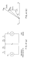
- FIG. 5 is a block diagram showing the structure of an electric propulsion system provided in a super-eco ship.
- This electric propulsion system includes a rotating electric machine 1 , a power supply unit 3 that supplies DC power, a power converting device 5 such as an inverter that converts the DC power supplied from the power supply unit 3 to AC power, and supplies the AC power to the rotating electric machine 1 , a pushing propeller 6 that is connected directly to the rotating electric machine 1 , and a field power supply 7 that supplies a field current to the rotating electric machine 1 .
- a power converting device 5 such as an inverter that converts the DC power supplied from the power supply unit 3 to AC power, and supplies the AC power to the rotating electric machine 1
- a pushing propeller 6 that is connected directly to the rotating electric machine 1
- a field power supply 7 that supplies a field current to the rotating electric machine 1 .
- a synchronous motor formed with a rotating field winding la and a stationary armature winding 1 b is used as the rotating electric machine 1
- the power supply unit 3 is normally formed with a power generator 3 a and a power engine 3 b connected to each other.
- the electric propulsion system shown in FIG. 5 operates the power engine on maximum output at all times (not shown in FIG. 5 , see FIG. 6 instead), and increases and reduces the electric power to be supplied to the rotating electric machine 1 with the power converting device 5 , so as to increase and reduce the propulsion power of the pushing propeller.
- this electric propulsion system In this electric propulsion system, the output of the power engine is always kept at a fixed value. Accordingly, compared with a conventional directly-connected propulsion machine, this electric propulsion system can restrict the toxic substance emission such as carbon dioxide emission to a much smaller amount, and can reduce the adverse influence on environments.
- this electric propulsion system uses a motor, a power generator, and a power converting device. Therefore, this electric propulsion system has lower transmission efficiency than a conventional directly-connected propulsion machine.
- FIG. 6( a ) is a schematic block diagram showing the transmission efficiency of the conventional electric propulsion system shown in FIG. 5 .
- each of the values having the symbol ⁇ attached thereto represents a loss (%)
- each of the values not having the symbol ⁇ attached thereto represents transmission efficiency (%).
- the numerical values shown on the upper side in FIG. 6( a ) represent the transmission efficiency (%) at a rated speed
- the numerical values shown on the lower side in FIG. 6( a ) represent the transmission efficiency (%) at a 1 ⁇ 2 vessel speed.
- the transmission efficiency of 79.7% at the rated speed, and the transmission efficiency of 63.3% at the 1 ⁇ 2 vessel speed are not sufficiently high, from a viewpoint of energy saving.
- the low transmission efficiency is mainly due to the rotating electric machine serving as a power generator or a motor having low transmission efficiency.
- the transmission efficiency of the entire electric propulsion system is expected to become higher by increasing the transmission efficiency of the rotating electric machine serving as a power generator or a motor.
- a load device 4 such as an industrial motor or a general electric power supply unit, instead of the power supply unit 3 , is connected in the power unit 2 .
- the rotating electric machine serving as a power generator or a motor is required to have higher transmission efficiency.
- the rotating electric machine becomes a low-voltage, large-current rotating electric machine, having a small induced electromotive force.
- the current density of the armature winding may be lowered.
- the rotating electric machine becomes larger in size, and therefore, there is a limit to the decrease in the current density.
- the present invention has been made in view of these circumstances, and an object thereof is to provide a superconductive rotating electric machine drive control system that has higher efficiency and is smaller size and lighter in weight than conventional systems, and also to provide a superconductive control method to be implemented in the superconductive rotating electric machine drive control system.
- a superconductive rotating electric machine drive control system including: a synchronous rotating electric machine that has a superconductive field winding and a copper armature winding or a superconductive armature winding; a power unit provided as a power supply unit that supplies power to the synchronous rotating electric machine or as a load unit that receives power from the synchronous rotating electric machine; an armature-side power converting device that converts electric power exchanged between the synchronous rotating electric machine and the power unit; a field power supply that supplies a field current to the synchronous rotating electric machine; a field-side power converting device that controls the current supplied from the field power supply to the superconductive field winding; an unified controller that coordinately controls the direct or alternating current flowing in the superconductive field winding and the copper armature winding or superconductive armature winding; and a refrigerating unit that cools down the superconductive field winding or both the superconductive field winding and the superconductive armature winding to a very low
- I f2 represents the field current applied to the superconductive field winding
- I represents the line current
- E 2 represents the induced electromotive force of the synchronous rotating electric machine
- V t represents the terminal voltage
- k 4 represents the constant
- n 2 represents the number of winding wires in the superconductive field winding
- ⁇ represents the rotation speed of the synchronous rotating electric machine
- r 2 represents the resistance of the synchronous rotating electric machine
- ⁇ 2 represent the reactance of the synchronous rotating electric machine.
- the unified controller may perform a control operation so that the field current I f2 applied to the superconductive field winding satisfies the following equation (18):
- a superconductive rotating electric machine drive control system including: a synchronous rotating electric machine that has a superconductive field winding and a copper armature winding or a superconductive armature winding; a power unit provided as a power supply unit that supplies power to the synchronous rotating electric machine or as a load unit that receives power from the synchronous rotating electric machine; an armature-side power converting device that converts electric power exchanged between the synchronous rotating electric machine and the power unit; a field power supply that supplies a field current to the synchronous rotating electric machine; a field-side power converting device that controls the current supplied from the field power supply to the superconductive field winding; an unified controller that coordinately controls the direct or alternating current flowing in the superconductive field winding and the copper armature winding or superconductive armature winding; and a refrigerating unit that cools down the superconductive field winding or both the superconductive field winding and the superconductive armature winding to a very low
- I f1 and I f2 represent the field currents respectively applied to the field winding of the power supply unit and the superconductive field winding
- I represents the line current
- E 1 and E 2 represent the induced electromotive forces of the power supply unit and the synchronous rotating electric machine
- V t represents the terminal voltage
- k 3 and k 4 represent the constants
- n 1 and n 2 represent the numbers of winding wires in the field winding of the power supply unit and the superconductive field winding of the synchronous rotating electric machine
- ⁇ represents the rotation speed of the synchronous rotating electric machine
- ⁇ represents the power factor angle
- r 1 and r 2 respectively represent the resistance of the power supply unit and the resistance of the synchronous rotating electric machine
- ⁇ 1 and ⁇ 2 respectively represent the reactance of the power supply unit and the reactance of the synchronous rotating electric machine.
- the unified controller may perform a control operation so that the field currents I f1 and I f2 respectively applied to the field winding of the power supply unit and the superconductive field winding of the synchronous rotating electric machine satisfy the following equations (16) and (17):
- I f2 ( ⁇ square root over ( V t 2 ⁇ x 2 2 I 2 ) ⁇ r 2 I )/ k 4 n 2 ⁇
- I f1 ⁇ square root over (( E t 2 +( r 1 +r 2 ) I ) 2 +( x 1 +x 2 ) 2 I 2 )) ⁇ square root over (( E t 2 +( r 1 +r 2 ) I ) 2 +( x 1 +x 2 ) 2 I 2 )) ⁇ / k 3 n 1 ⁇ (17)
- the unified controller may perform a control operation so that the field currents I f1 and I f2 respectively applied to the field winding of the power supply unit and the superconductive field winding of the synchronous rotating electric machine satisfy the following equations (18) and (19):
- a superconductive rotating electric machine drive control system including: a synchronous rotating electric machine that has a superconductive field winding and a copper armature winding or a superconductive armature winding; a power unit provided as a power supply unit that supplies power to the synchronous rotating electric machine or as a load unit that receives power from the synchronous rotating electric machine; an armature-side power converting device that converts electric power exchanged between the synchronous rotating electric machine and the power unit; a field power supply that supplies a field current to the synchronous rotating electric machine; a field-side power converting device that controls the current supplied from the field power supply to the superconductive field winding; an unified controller that coordinately controls the direct or alternating current flowing in the superconductive field winding and the copper armature winding or superconductive armature winding; and a refrigerating unit that cools down the superconductive field winding or both the superconductive field winding and the superconductive armature winding to a very low
- I f2 represents the field current applied to the superconductive field winding
- I represents the line current
- V t represents the terminal voltage
- k 4 represents the constant
- n 2 represents the number of winding wires in the superconductive field winding
- ⁇ represents the rotation speed of the synchronous rotating electric machine
- ⁇ represents the power factor angle
- r 2 represents the resistance of the synchronous rotating electric machine
- ⁇ 2 represent the reactance of the synchronous rotating electric machine.
- the power supply unit may be formed with a copper power generator or a superconductive power generator and a power engine connected to each other.
- the superconductive rotating electric machine drive control system may further include a superconductive transformer that has at least a superconductive winding as the winding on the synchronous rotating electric machine side, and variably adjusts the voltage.
- This superconductive transformer may be placed between the synchronous rotating electric machine and the armature-side power converting device.
- the superconductive rotating electric machine drive control system may further include a power converting device that includes an inverter, a converter, or a cyclo-converter.
- This power converting device may be placed on the synchronous rotating electric machine side of the superconductive transformer or on the opposite side of the superconductive transformer from the synchronous rotating electric machine side.
- the superconductive rotating electric machine drive control system may further include an inductive power collector that has a superconductive coil on the rotor side and includes a rotary transformer that variably adjusts the voltage.
- This inductive power collector may be placed between the field power supply and the field-side power converting device.
- the superconductive rotating electric machine drive control system may further include a power converting device that includes an inverter, a converter, or a cyclo-converter. This power converting device may be placed on the rotor or stator side of the inductive power collector.
- the power converting device provided on the rotor side of the inductive power collector may be an AC/DC converter.
- the superconductive rotating electric machine drive control system may further include a propeller that is connected to the synchronous rotating electric machine.
- a superconductive rotating electric machine drive control method implemented in a superconductive rotating electric machine drive control system, the superconductive rotating electric machine drive control system including: a synchronous rotating electric machine that has a superconductive field winding and a copper armature winding or a superconductive armature winding; a power unit provided as a power supply unit that supplies power to the synchronous rotating electric machine or as a load unit that receives power from the synchronous rotating electric machine; an armature-side power converting device that converts electric power exchanged between the synchronous rotating electric machine and the power unit; a field power supply that supplies a field current to the synchronous rotating electric machine; a field-side power converting device that controls the current supplied from the field power supply to the superconductive field winding; an unified controller that coordinately controls the direct or alternating current flowing in the superconductive field winding and the copper armature winding or superconductive armature winding; and a refrigerating unit that cools down the superconductive field winding
- I f2 represents the field current applied to the superconductive field winding
- I represents the line current
- E 2 represents the induced electromotive force of the synchronous rotating electric machine
- V t represents the terminal voltage
- k 4 represents the constant
- n 2 represents the number of winding wires in the superconductive field winding
- ⁇ represents the rotation speed of the synchronous rotating electric machine
- ⁇ represents the power factor angle
- r 2 represents the resistance of the synchronous rotating electric machine
- ⁇ 2 represent the reactance of the synchronous rotating electric machine.
- a control operation may be performed with the use of the unified controller, so that the field current I f2 applied to the superconductive field winding satisfies the following equation (18):
- a superconductive rotating electric machine drive control method implemented in a superconductive rotating electric machine drive control system, the superconductive rotating electric machine drive control system including: a synchronous rotating electric machine that has a superconductive field winding and a copper armature winding or a superconductive armature winding; a power unit provided as a power supply unit that supplies power to the synchronous rotating electric machine or as a load unit that receives power from the synchronous rotating electric machine; an armature-side power converting device that converts electric power exchanged between the synchronous rotating electric machine and the power unit; a field power supply that supplies a field current to the synchronous rotating electric machine; a field-side power converting device that controls the current supplied from the field power supply to the superconductive field winding; an unified controller that coordinately controls the direct or alternating current flowing in the superconductive field winding and the copper armature winding or superconductive armature winding; and a refrigerating unit that cools down the superconductive field winding
- I f1 and I f2 represent the field currents respectively applied to the field winding of the power supply unit and the superconductive field winding
- I represents the line current
- E 1 and E 2 represent the induced electromotive forces of the power supply unit and the synchronous rotating electric machine
- V t represents the terminal voltage
- k 3 and k 4 represent the constants
- n 1 and n 2 represent the numbers of winding wires in the field winding of the power supply unit and the superconductive field winding of the synchronous rotating electric machine
- ⁇ represents the rotation speed of the synchronous rotating electric machine
- ⁇ represents the power factor angle
- r 1 and r 2 respectively represent the resistance of the power supply unit and the resistance of the synchronous rotating electric machine
- ⁇ 1 and ⁇ 2 respectively represent the reactance of the power supply unit and the reactance of the synchronous rotating electric machine.
- a control operation may be performed with the use of the unified controller, so that the field currents I f1 and I f2 respectively applied to the field winding of the power supply unit and the superconductive field winding of the synchronous rotating electric machine satisfy the following equations (16) and (17):
- I f2 ( ⁇ square root over ( V t 2 ⁇ x 2 2 I 2 ) ⁇ r 2 I )/ k 4 n 2 ⁇
- I f1 ⁇ square root over (( E t 2 +( r 1 +r 2 ) I ) 2 +( x 1 +x 2 ) 2 I 2 )) ⁇ square root over (( E t 2 +( r 1 +r 2 ) I ) 2 +( x 1 +x 2 ) 2 I 2 )) ⁇ / k 3 n 1 ⁇ (17)
- a control operation may be performed with the use of the unified controller, so that the field currents I f1 and I f2 respectively applied to the field winding of the power supply unit and the superconductive field winding of the synchronous rotating electric machine satisfy the following equations (18) and (19):
- a superconductive rotating electric machine drive control method implemented in a superconductive rotating electric machine drive control system, the superconductive rotating electric machine drive control system including: a synchronous rotating electric machine that has a superconductive field winding and a copper armature winding or a superconductive armature winding; a power unit provided as a power supply unit that supplies power to the synchronous rotating electric machine or as a load unit that receives power from the synchronous rotating electric machine; an armature-side power converting device that converts electric power exchanged between the synchronous rotating electric machine and the power unit; a field power supply that supplies a field current to the synchronous rotating electric machine; a field-side power converting device that controls the current supplied from the field power supply to the superconductive field winding; an unified controller that coordinately controls the direct or alternating current flowing in the superconductive field winding and the copper armature winding or superconductive armature winding; and a refrigerating unit that cools down the superconductive field winding
- I f2 represents the field current applied to the superconductive field winding
- I represents the line current
- V t represents the terminal voltage
- k 4 represents the constant
- n 2 represents the number of winding wires in the superconductive field winding
- ⁇ represents the rotation speed of the synchronous rotating electric machine
- ⁇ represents the power factor angle
- r 2 represents the resistance of the synchronous rotating electric machine
- ⁇ 2 represent the reactance of the synchronous rotating electric machine.
- FIG. 1 is a block diagram showing the structure of a superconductive rotating electric machine drive control system in accordance with an embodiment of the present invention in which a superconductive rotating electric machine drive control method in accordance with an embodiment of the present invention is implemented;
- FIG. 2 is a graph showing the V characteristics representing the relationship between the field current and the armature current of each of a superconductive device and a conventional device;
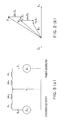
- FIG. 3( a ) is an equivalent circuit diagram of an example case where the synchronous rotating electric machine 1 of the superconductive rotating electric machine drive control of the embodiment shown in FIG. 1 is a synchronous motor;
- FIG. 3( b ) is a vector diagram of an example case where the synchronous rotating electric machine 1 of the superconductive rotating electric machine drive control of the embodiment shown in FIG. 1 is a synchronous motor;
- FIG. 4( a ) is an equivalent circuit diagram of an example case where the synchronous rotating electric machine 1 of the superconductive rotating electric machine drive control of the embodiment shown in FIG. 1 is a synchronous power generator;
- FIG. 4( b ) is a vector diagram of an example case where the synchronous rotating electric machine 1 of the superconductive rotating electric machine drive control of the embodiment shown in FIG. 1 is a synchronous power generator;
- FIG. 5 is a block diagram showing the structure of an electric propulsion system provided in a super-eco ship
- FIG. 6( a ) is a schematic block diagram showing the transmission efficiency of the conventional electric propulsion system shown in FIG. 5 ;
- FIG. 6( b ) is a schematic block diagram showing the transmission efficiency of the superconductive rotating electric machine drive control system in accordance with the embodiment of the present invention in which the superconductive rotating electric machine drive control method in accordance with the embodiment of the present invention is implemented.
- FIG. 1 is a block diagram showing the structure of the superconductive rotating electric machine drive control system that has the superconductive rotating electric machine drive control method implemented therein.
- the superconductive rotating electric machine drive control system in accordance with the embodiment of the present invention includes: a synchronous rotating electric machine 1 that has a superconductive field winding 1 c and a copper armature winding or a superconductive armature winding 1 d; a power unit 2 provided as a power supply unit 3 that supplies power to the synchronous rotating electric machine 1 or as a load unit 4 that receives power from the synchronous rotating electric machine 1 ; an armature-side power converting device 5 such as an inverter, a converter, or a cyclo-converter that converts the power exchanged between the synchronous rotating electric machine 1 and the power unit 2 ; a field power supply 7 that supplies a field current to the synchronous rotating electric machine 1 ; a field-side power converting device 10 such as an inverter, a converter, or a cycle-converter that controls the current supplied from the field power supply 7 to the superconductive field winding 1 c; an unified controller 8 that controls the direct or alternating current flowing in the superconductive
- the unified controller 8 in which the superconductive rotating electric machine drive control method of this embodiment performs a control operation so that the field current flowing in the superconductive field winding 1 c of the synchronous rotating electric machine 1 satisfies the later mentioned equation (11), in accordance with the variation of the electric power exchanged between the synchronous rotating electric machine 1 and the power unit 2 , or the output fluctuation. Therefore, the value of the power exchanged between the synchronous rotating electric machine 1 and the power unit 2 is fed back to the unified controller 8 .
- a propeller 6 may be connected to the synchronous rotary electric machine 1 , for example.
- the power supply unit 3 is normally formed with a copper power generator or a superconductive power generator 3 c and a motor 3 b.
- the superconductive transformer 11 has at least a superconductive winding as the winding on the side of the synchronous rotating electric machine 1 , and the winding on the side of the armature-side power converting device 5 may be either a superconductive winding or a copper winding.
- a power converting device may be further provided on the side of the rotor or stator of the superconductive transformer 11 .
- FIG. 2 is a graph showing the V characteristics representing the relationship between the field current and the armature current of each of a superconductive device and a conventional device.
- the curves S 0 , S 1 , and S 2 represent the V characteristics of the superconductive device when the load is 0%, 50%, and 100%.
- the curves P 0 , P 1 , and P 2 represent the V characteristics of the conventional device when the load is 0%, 50%, and 100%.
- the power factor is 100%, as the armature current becomes highest when the power factor is 100%.
- each of the curves shifts to the leading power factor region.
- each of the curves shifts to the lagging power factor region.
- the armature current becomes higher both in the leading power factor region and the lagging power factor region.
- the armature current gently changes as the field current changes. Accordingly, the V curves of the conventional device are gentle curves, as indicated by the curves P 0 , P 1 , and P 2 .
- the synchronous reactance is small. Accordingly, the armature current rapidly changes as the field current varies. As indicated by the curves S 0 , S 1 , and S 2 , the V curves of the superconductive device are steep curves.
- the operating point needs to be controlled to stay at point A.
- FIG. 3( a ) is an equivalent circuit diagram of a structure in which the synchronous rotating electric machine 1 of the superconductive rotating electric machine drive control system of the embodiment shown in FIG. 1 is a synchronous motor.
- FIG. 3( b ) is a vector diagram of the same structure.
- FIG. 4( a ) is an equivalent circuit diagram of a structure in which the synchronous rotating electric machine 1 is a synchronous power generator.
- FIG. 4( b ) is a vector diagram of the same structure.
- FIGS. 3( a ) and 3 ( b ) and FIGS. 4( a ) and 4 ( b ) the principles of coordinated control performed by the unified controller 8 on the field current and the armature current in the superconductive rotating electric machine drive control system of this embodiment in which the superconductive rotating electric machine drive control method of this embodiment is implemented are described.
- E 1 and E 2 represent the induced electromotive forces of the power generator (the power generator 3 c of FIG. 1 ) and the synchronous motor (the synchronous rotating electric machine 1 of FIG. 1 ),
- V t represents the terminal voltage
- r 1 and ⁇ 1 represent the resistance and the reactance of the power generator
- r 2 and ⁇ 2 represent the resistance and the reactance of the synchronous motor
- ⁇ represents the power factor angle.
- E 1 and E 2 of the synchronous motor and the power generator, the input power P i of the power generator, and the output power R 0 of the synchronous motor are expressed by the following equations:
- P i 3 V t I cos ⁇ + W 1
- P o 3 V t I cos ⁇ W 2 (8)
- k 1 , k 2 , k 3 , and k 4 represent the constants
- ⁇ 1 and ⁇ 2 represent the effective field fluxes of the power generator and the synchronous motor
- n 1 and n 2 represent the numbers of field winding wires in the power generator and the synchronous motor
- I f1 and I f2 represent the field currents of the power generator and the synchronous motor
- W 2 copper loss r 2 I 2 +iron loss+mechanical loss+excitation loss+cooling power).
- the field currents I f1 and I f2 of the synchronous power generator and the synchronous motor are determined by defining E 1 and E 2 , and assigning the defined values to the equations (5) and (6).
- the field currents I f1 and I f2 of the synchronous power generator and the synchronous motor are coordinately controlled in accordance with the load condition, so that the synchronous motor can keep operating while maintaining the desired power factor ⁇ and the load angle ⁇ 2 , even when the load condition varies.
- I f1 ⁇ square root over (( E t 2 +( r 1 +r 2 ) I ) 2 +( x 1 +x 2 ) 2 I 2 )) ⁇ square root over (( E t 2 +( r 1 +r 2 ) I ) 2 +( x 1 +x 2 ) 2 I 2 )) ⁇ / k 3 n 1 ⁇ (17)
- the power factor ⁇ can be sensed by detecting the terminal voltage V t and the line current I.
- the load angles ⁇ 1 and ⁇ 2 can be sensed by detecting the locations of the terminal voltage V t and the induced electromotive forces E 1 and E 2 .
- I f2 ⁇ square root over (( V t cos ⁇ + 2 I ) 2 +( V t sin ⁇ + x 2 I ) 2 ) ⁇ square root over (( V t cos ⁇ + 2 I ) 2 +( V t sin ⁇ + x 2 I ) 2 ) ⁇ / k 4 n 2 ⁇ (20)
- the power factor angle ⁇ can be maintained at a constant value during operation.
- the superconductive rotating electric machine drive control system and the superconductive rotating electric machine drive control method of this embodiment are implemented in an electric propulsion system such as a ship electric propulsion system required to have low-speed large torque, the induced electromotive force accompanying the low speed can be compensated by a powerful superconductive field flux.
- FIG. 6( b ) is a schematic block diagram showing the transmission efficiency of the superconductive rotating electric machine drive control system of this embodiment in which the superconductive rotating electric machine drive control method of this embodiment is implemented.
- each of the values having the symbol ⁇ attached thereto represents a loss (%)
- each of the values not having the symbol ⁇ attached thereto represents transmission efficiency (%).
- the transmission efficiency has the same value at a rated speed or a 1 ⁇ 2 vessel speed.
- the transmission efficiency of an electric propulsion system employing the superconductive rotating electric machine drive control system of this embodiment in which the superconductive rotating electric machine drive control method of this embodiment is implemented has the values shown in FIG. 6( b ).
- the transmission efficiency is approximately 10% higher during the rated operation and is approximately 26% higher at the 1 ⁇ 2 vessel speed, compared with the transmission efficiency observed in a case of a conventional electric propulsion system shown in FIG. 6( a ).
- the superconductive rotating electric machine drive control system of this embodiment having the unified controller 8 that performs control by the superconductive rotating electric machine drive control method of this embodiment so that the field current applied to the superconductive field winding 1 c of the synchronous rotating electric machine 1 satisfies the equation (11) in accordance with the variation of the power exchanged between the synchronous rotating electric machine 1 and the power unit 2 or on the output variation, a superconductive coil for supplying a field current is provided on the side of the rotor, and an inductive power collector 9 of a rotary transformer type that variably adjusts the voltage is provided between the field power supply 7 and the field-side power converting device 10 .
- the field circuit in the rotor can be integrally made superconductive, and low-loss excitation and easy heat insulation can be realized.
- the armature structure can be simplified, and the required capacity of the refrigerating unit 12 can be made smaller.
- the power converting device (an AC/DC converting device) 10 is provided on the rotor side of the inductive power collector 9 , since the inductive power collector 9 can supply only an alternating current.
- the power converting device 10 such as a converter, an inverter, or a cyclo-converter is provided on the rotor side or the stator side. With this arrangement, the amount of field current can be readily controlled.
- the superconductive transformer 11 that includes a superconductive coil and variably adjusts the voltage is provided at an electric machine side spot between the synchronous rotating electric machine 1 and the power unit 2 .
- the superconductive transformer 11 includes at least a superconductive winding or a superconductive coil as the winding provided on the side of the synchronous rotating electric machine 1 .
- the winding on the side of the armature-side power converting device 5 may be either a superconductive winding or a copper winding.
- the power converting device 10 such as an inverter, a converter, or a cyclo-converter is provided on the rotating electric machine side or the power unit side of the superconductive transformer 11 , so that the amount of armature current can be readily controlled.
- the propeller 6 is connected to the synchronous rotating electric machine 1 , so that the system can be used for the ship propulsion, wind-power generation, and the likes.
- high-efficiency operation control with high power factor can be achieved.
- the synchronous rotating electric machine 1 is operated as a power generator, and the power unit 2 is used as a rotational or linear motor or as the load unit 4 of a hydrogen energy generating device or a general power supply device or the like.
- this system can be used as the high-efficiency power supply device of a transportation/industrial system motor or a dispersed power and electric power generator or the like.
- this system can be used in wider fields.
- the superconductive rotating electric machine drive control system of this embodiment having the unified controller 8 that performs a control operation by the superconductive rotating electric machine drive control method of this embodiment so that the field current applied to the superconductive field winding 1 c of the synchronous rotating electric machine 1 satisfies the equation (11) in accordance with the output variation, the synchronous rotating electric machine 1 is operated as a motor, and the power unit 2 is used as a power supply equipped with a power engine and a superconductive power generator. In this manner, this system can be used as a high-efficiency electric drive system. Thus, this system can be used in wider fields.
- the superconductive rotating electric machine drive control system of this embodiment includes the unified controller 8 that performs a control operation by the superconductive rotating electric machine drive control method of this embodiment so that the field current applied to the superconductive field winding 1 c of the synchronous rotating electric machine 1 satisfies the equation (11) in accordance with the variation of the electric power exchanged between the synchronous rotating electric machine 1 and the power unit 2 or on the output variation. Accordingly, this embodiment can provide a small-sized, light-weight superconductive rotating electric machine drive control system that can constantly perform drive control on low-voltage large current with high power factor at high efficiency, regardless of changes in operating conditions such as load fluctuations.
- this embodiment can provide a superconductive rotating electric machine drive control method for constantly performing drive control on low-voltage large current with high power factor at high efficiency, regardless of changes in operating conditions such as load fluctuations.
Landscapes
- Engineering & Computer Science (AREA)
- Power Engineering (AREA)
- Chemical & Material Sciences (AREA)
- Combustion & Propulsion (AREA)
- Mechanical Engineering (AREA)
- Ocean & Marine Engineering (AREA)
- Control Of Ac Motors In General (AREA)
- Control Of Eletrric Generators (AREA)
Abstract
Description
I f2 =E 2 /k 4 n 2ν=√{square root over ((V t cos θ−r 2 I)2+(V t sin θ−x 2 I)2)}{square root over ((V t cos θ−r 2 I)2+(V t sin θ−x 2 I)2)}/k 4 n 2ν (11)
I f2=(√{square root over (V t 2 −x 2 2 I 2)}−r 2 I)/k 4 n 2ν (16)
I f2 =E 2 /k 4 n 2ν=√{square root over ((V t −r 2 I)2+(−x 2 I)2)}{square root over ((V t −r 2 I)2+(−x 2 I)2)}/k 4 n 2ν (18)
I f2 =E 2 /k 4 n 2ν=√{square root over ((V t cos θ−r 2 I)2+(V t sin θ−x 2 I)2)}{square root over ((V t cos θ−r 2 I)2+(V t sin θ−x 2 I)2)}/k 4 n 2ν (11)
I f1 =E 1 /k 3 n 1ν=√{square root over ((V t cos θ+r 2 I)2+(V t sin θ+x 2 I)2)}{square root over ((V t cos θ+r 2 I)2+(V t sin θ+x 2 I)2)}/k 3 n 1ν (12)
I f2=(√{square root over (V t 2 −x 2 2 I 2)}−r 2 I)/k 4 n 2ν (16)
I f1=√{square root over ((E t 2+(r 1 +r 2)I)2+(x 1 +x 2)2 I 2))}{square root over ((E t 2+(r 1 +r 2)I)2+(x 1 +x 2)2 I 2))}/k 3 n 1ν (17)
I f2 =E 2 /k 4 n 2ν=√{square root over ((V t −r 2 I)2+(−x 2 I)2)}{square root over ((V t −r 2 I)2+(−x 2 I)2)}/k 4 n 2ν (18)
I f1 =E 1 /k 3 n 1ν=√{square root over ((V t +r 1 I)2+(x 1 I)2)}{square root over ((V t +r 1 I)2+(x 1 I)2)}/k 3 n 1 (19)
I f2=√{square root over ((V t cos θ+2 I)2+(V t sin θ+x 2 I)2)}{square root over ((V t cos θ+2 I)2+(V t sin θ+x 2 I)2)}/ k 4 n 2ν (20)
I f2 =E 2 /k 4 n 2ν=√{square root over ((V t cos θ−r 2 I)2+(V t sin θ−x 2 I)2)}{square root over ((V t cos θ−r 2 I)2+(V t sin θ−x 2 I)2)}/k 4 n 2ν (11)
I f2=(√{square root over (V t 2 −x 2 2 I 2)}−r 2 I)/k 4 n 2ν (16)
I f2 =E 2 /k 4 n 2ν=√{square root over ((V t −r 2 I)2+(−x 2 I)2)}{square root over ((V t −r 2 I)2+(−x 2 I)2)}/k 4 n 2ν (18)
I f2 =E 2 /k 4 n 2ν=√{square root over ((V t cos θ−r 2 I)2+(V t sin θ−x 2 I)2)}{square root over ((V t cos θ−r 2 I)2+(V t sin θ−x 2 I)2)}/k 4 n 2ν (11)
I f1 =E 1 /k 3 n 1ν=√{square root over ((V t cos θ+r 2 I)2+(V t sin θ+x 2 I)2)}{square root over ((V t cos θ+r 2 I)2+(V t sin θ+x 2 I)2)}/k 3 n 1ν (12)
I f2=(√{square root over (V t 2 −x 2 2 I 2)}−r 2 I)/k 4 n 2ν (16)
I f1=√{square root over ((E t 2+(r 1 +r 2)I)2+(x 1 +x 2)2 I 2))}{square root over ((E t 2+(r 1 +r 2)I)2+(x 1 +x 2)2 I 2))}/k 3 n 1ν (17)
I f2 =E 2 /k 4 n 2ν=√{square root over ((V t −r 2 I)2+(−x 2 I)2)}{square root over ((V t −r 2 I)2+(−x 2 I)2)}/k 4 n 2ν (18)
I f1 =E 1 /k 3 n 1ν=√{square root over ((V t +r 1 I)2+(x 1 I)2)}{square root over ((V t +r 1 I)2+(x 1 I)2)}/k 3 n 1 (19)
I f2=√{square root over ((V t cos θ+2 I)2+(V t sin θ+x 2 I)2)}{square root over ((V t cos θ+2 I)2+(V t sin θ+x 2 I)2)}/ k 4 n 2ν (20)
E 1 cos(θ+δ1)−r 1 I=V t cos θ (1)
E 1 sin(θ+δ1)−x 1 I=V t sin θ (2)
E 2 cos(θ−δ2)+r 2 I=V t cos θ (3)
E 2 sin(θ−δ2)+x 2 I=V t sin θ (4)
E1=k1Φ1ν1=k3n1If1ν1 (5)
E2=k2Φ2ν2=k4n2If2ν2 (6)
P i=3V t I cos θ+W 1 (7)
P o=3V t I cos θ−W 2 (8)
(V t cos θ−r 2 I)2+(V t sin θ−x 2 I)2 =E 2 2 (9)
(V t cos θ+r 1 I)2+(V t sin θ+x 1 I)2 =E 1 2 (10)
I f2 =E 2 /k 4 n 2ν=√{square root over ((V t cos θ−r 2 I)2+(V t sin θ−x 2 I)2)}{square root over ((V t cos θ−r 2 I)2+(V t sin θ−x 2 I)2)}/k 4 n 2ν (11)
I f1 =E 1 /k 3 n 1ν=√{square root over ((V t cos θ+r 2 I)2+(V t sin θ+x 2 I)2)}{square root over ((V t cos θ+r 2 I)2+(V t sin θ+x 2 I)2)}/k 3 n 1ν (12)
E 2 +r 2 I=V t cos θ (13)
x2I=Vt sin θ (14)
(E 2 +r 2 I)2 +x 2 2 I 2 =V t 2 (15)
I f2=(√{square root over (V t 2 −x 2 2 I 2)}−r 2 I)/k 4 n 2ν (16)
I f1=√{square root over ((E t 2+(r 1 +r 2)I)2+(x 1 +x 2)2 I 2))}{square root over ((E t 2+(r 1 +r 2)I)2+(x 1 +x 2)2 I 2))}/k 3 n 1ν (17)
I f2 =E 2 /k 4 n 2ν=√{square root over ((V t −r 2 I)2+(−x 2 I)2)}{square root over ((V t −r 2 I)2+(−x 2 I)2)}/k 4 n 2ν (18)
I f1 =E 1 /k 3 n 1ν=√{square root over ((V t +r 1 I)2+(x 1 I)2)}{square root over ((V t +r 1 I)2+(x 1 I)2)}/k 3 n 1 (19)
E 2 cos(θ−δ12)+r 2 I=V t cos θ
E 2 sin(θ+δ2)−x 2 I=V t sin θ
(V t cos θ+r 2 I)2+(V t sin θ+x 2 I)2 =E 2 2
I f2=√{square root over ((V t cos θ+2 I)2+(V t sin θ+x 2 I)2)}{square root over ((V t cos θ+2 I)2+(V t sin θ+x 2 I)2)}/ k 4 n 2ν (20)
Claims (35)
I f2 =E 2 /k 4 n 2ν=√{square root over ((V t cos θ−r 2 I)2+(V t sin θ−x 2 I)2)}{square root over ((V t cos θ−r 2 I)2+(V t sin θ−x 2 I)2)}/k 4 n 2ν (11)
I f2=(√{square root over (V t 2 −x 2 2 I 2)}−r 2 I)/k 4 n 2ν (16)
I f2 =E 2 /k 4 n 2ν=√{square root over ((V t −r 2 I)2+(−x 2 I)2)}{square root over ((V t −r 2 I)2+(−x 2 I)2)}/k 4 n 2ν (18)
I f2 =E 2 /k 4 n 2ν=√{square root over ((V t cos θ−r 2 I)2+(V t sin θ−x 2 I)2)}{square root over ((V t cos θ−r 2 I)2+(V t sin θ−x 2 I)2)}/k 4 n 2ν (11)
I f1 =E 1 /k 3 n 1ν=√{square root over ((V t cos θ+r 2 I)2+(V t sin θ+x 2 I)2)}{square root over ((V t cos θ+r 2 I)2+(V t sin θ+x 2 I)2)}/k 3 n 1ν (12)
I f2=(√{square root over (V t 2 −x 2 2 I 2)}−r 2 I)/k 4 n 2ν (16)
I f1=√{square root over ((E t 2+(r 1 +r 2)I)2+(x 1 +x 2)2 I 2))}{square root over ((E t 2+(r 1 +r 2)I)2+(x 1 +x 2)2 I 2))}/k 3 n 1ν (17)
I f2 =E 2 /k 4 n 2ν=√{square root over ((V t −r 2 I)2+(−x 2 I)2)}{square root over ((V t −r 2 I)2+(−x 2 I)2)}/k 4 n 2ν (18)
I f1 =E 1 /k 3 n 1ν=√{square root over ((V t +r 1 I)2+(x 1 I)2)}{square root over ((V t +r 1 I)2+(x 1 I)2)}/k 3 n 1 (19)
I f2=√{square root over ((V t cos θ+2 I)2+(V t sin θ+x 2 I)2)}{square root over ((V t cos θ+2 I)2+(V t sin θ+x 2 I)2)}/ k 4 n 2ν (20)
I f2 =E 2 /k 4 n 2ν=√{square root over ((V t cos θ−r 2 I)2+(V t sin θ−x 2 I)2)}{square root over ((V t cos θ−r 2 I)2+(V t sin θ−x 2 I)2)}/k 4 n 2ν (11)
I f2=(√{square root over (V t 2 −x 2 2 I 2)}−r 2 I)/k 4 n 2ν (16)
I f2 =E 2 /k 4 n 2ν=√{square root over ((V t −r 2 I)2+(−x 2 I)2)}{square root over ((V t −r 2 I)2+(−x 2 I)2)}/k 4 n 2ν (18)
I f2 =E 2 /k 4 n 2ν=√{square root over ((V t cos θ−r 2 I)2+(V t sin θ−x 2 I)2)}{square root over ((V t cos θ−r 2 I)2+(V t sin θ−x 2 I)2)}/k 4 n 2ν (11)
I f1 =E 1 /k 3 n 1ν=√{square root over ((V t cos θ+r 2 I)2+(V t sin θ+x 2 I)2)}{square root over ((V t cos θ+r 2 I)2+(V t sin θ+x 2 I)2)}/k 3 n 1ν (12)
I f2=(√{square root over (V t 2 −x 2 2 I 2)}−r 2 I)/k 4 n 2ν (16)
I f1=√{square root over ((E t 2+(r 1 +r 2)I)2+(x 1 +x 2)2 I 2))}{square root over ((E t 2+(r 1 +r 2)I)2+(x 1 +x 2)2 I 2))}/k 3 n 1ν (17)
I f2 =E 2 /k 4 n 2ν=√{square root over ((V t −r 2 I)2+(−x 2 I)2)}{square root over ((V t −r 2 I)2+(−x 2 I)2)}/k 4 n 2ν (18)
I f1 =E 1 /k 3 n 1ν=√{square root over ((V t +r 1 I)2+(x 1 I)2)}{square root over ((V t +r 1 I)2+(x 1 I)2)}/k 3 n 1 (19)
I f2=√{square root over ((V t cos θ+2 I)2+(V t sin θ+x 2 I)2)}{square root over ((V t cos θ+2 I)2+(V t sin θ+x 2 I)2)}/ k 4 n 2ν (20)
Applications Claiming Priority (3)
| Application Number | Priority Date | Filing Date | Title |
|---|---|---|---|
| JP2006-302923 | 2006-11-08 | ||
| JP2006302923A JP4882053B2 (en) | 2006-11-08 | 2006-11-08 | Superconducting rotating electrical machine drive control system |
| PCT/JP2007/071201 WO2008056580A1 (en) | 2006-11-08 | 2007-10-31 | Superconductive rotating electric machine drive control system and superconductive rotating electric machine drive control method |
Publications (2)
| Publication Number | Publication Date |
|---|---|
| US20100066299A1 US20100066299A1 (en) | 2010-03-18 |
| US8076894B2 true US8076894B2 (en) | 2011-12-13 |
Family
ID=39364400
Family Applications (1)
| Application Number | Title | Priority Date | Filing Date |
|---|---|---|---|
| US12/513,386 Expired - Fee Related US8076894B2 (en) | 2006-11-08 | 2007-10-31 | Superconductive rotating electric machine drive control system and superconductive rotating electric machine drive control method |
Country Status (4)
| Country | Link |
|---|---|
| US (1) | US8076894B2 (en) |
| EP (1) | EP2117111A4 (en) |
| JP (1) | JP4882053B2 (en) |
| WO (1) | WO2008056580A1 (en) |
Cited By (1)
| Publication number | Priority date | Publication date | Assignee | Title |
|---|---|---|---|---|
| WO2014005593A2 (en) | 2012-07-02 | 2014-01-09 | Danmarks Tekniske Universitet | A control system for and a method of controlling a superconductive rotating electrical machine |
Families Citing this family (18)
| Publication number | Priority date | Publication date | Assignee | Title |
|---|---|---|---|---|
| DE102005047551A1 (en) * | 2005-09-30 | 2007-04-12 | Siemens Ag | Exciter device for an electrical machine |
| JP5362446B2 (en) * | 2009-05-29 | 2013-12-11 | アイシン精機株式会社 | Superconducting device |
| DE102010040907A1 (en) * | 2010-09-16 | 2012-03-22 | Aloys Wobben | Electric motor replacement |
| DE102011082365A1 (en) | 2011-09-08 | 2013-03-14 | Siemens Ag | Superconducting machine and method for its operation |
| KR101380024B1 (en) * | 2012-12-21 | 2014-04-02 | 두산엔진주식회사 | System for controlling super conduction generator |
| KR101445006B1 (en) * | 2012-12-27 | 2014-09-26 | 두산엔진주식회사 | System for controlling superconduction generator for homopolar type |
| EP2908004B1 (en) * | 2013-01-15 | 2016-10-12 | Mitsubishi Heavy Industries, Ltd. | Wind power generation facility, method for operating same, and wind farm control device |
| DE102014208437A1 (en) * | 2014-05-06 | 2015-11-12 | Siemens Aktiengesellschaft | Cooling device for at least two components to be cooled, rail vehicle and method of cooling |
| WO2016033214A1 (en) * | 2014-08-26 | 2016-03-03 | Innovus Power, Inc. | Power system and method |
| DE102014224363A1 (en) * | 2014-11-28 | 2016-06-02 | Siemens Aktiengesellschaft | Device of superconducting technology with coil devices and cooling device as well as vehicle equipped therewith |
| JP6391069B2 (en) * | 2015-01-20 | 2018-09-19 | ジャパンスーパーコンダクタテクノロジー株式会社 | Induction superconducting motor control circuit |
| US12311772B2 (en) | 2018-03-19 | 2025-05-27 | Tula eTechnology, Inc. | Pulse modulated control with field weakening for improved machine efficiency |
| JP7082679B2 (en) | 2018-03-19 | 2022-06-08 | トゥラ イーテクノロジー,インコーポレイテッド | Pulsed electromechanical control |
| US12609646B2 (en) | 2018-03-19 | 2026-04-21 | Tula eTechnology, Inc. | Boosted converter for pulsed electric machine control |
| WO2023278139A1 (en) | 2021-06-28 | 2023-01-05 | Tula eTechnology, Inc. | Selective phase control of an electric machine |
| JP7192071B1 (en) | 2021-10-04 | 2022-12-19 | 西芝電機株式会社 | Shaft drive generator and propulsion motor system |
| CN118830193A (en) | 2022-03-22 | 2024-10-22 | 图拉技术公司 | Delay reduction of pulse wound excitation synchronous machine |
| US12370907B2 (en) | 2023-10-17 | 2025-07-29 | Tula eTechnology, Inc. | On-pulse transition times for pulsed controlled electric machines using boost voltages |
Citations (8)
| Publication number | Priority date | Publication date | Assignee | Title |
|---|---|---|---|---|
| JPH0458799A (en) | 1990-06-28 | 1992-02-25 | Toshiba Corp | Exciter for synchronous machine |
| US5801500A (en) * | 1995-03-18 | 1998-09-01 | Danfoss A/S | Motor/compressor combination having a control arrangement for starting the motor with asynchronous and then synchronous commutation |
| US6362588B1 (en) | 2000-02-09 | 2002-03-26 | Reliance Electric Technologies, Llc | Excitation system for rotating synchronous machines |
| US6650083B2 (en) * | 2000-10-19 | 2003-11-18 | Lg Electronics Inc. | Speed control apparatus of synchronous reluctance motor and method thereof |
| JP2004135477A (en) | 2002-10-15 | 2004-04-30 | Jfe Steel Kk | Operation control method for synchronous motor |
| JP2004282979A (en) | 2003-03-13 | 2004-10-07 | C & S Kokusai Kenkyusho:Kk | Vector control method and its device for hybrid field synchronous motor |
| US20040245949A1 (en) * | 2003-04-30 | 2004-12-09 | Mitsuo Ueda | Motor driving apparatus |
| JP2005237175A (en) | 2004-02-23 | 2005-09-02 | Sumitomo Electric Ind Ltd | Motor and electric vehicle including the motor |
Family Cites Families (1)
| Publication number | Priority date | Publication date | Assignee | Title |
|---|---|---|---|---|
| DE20214297U1 (en) * | 2002-09-14 | 2004-02-12 | Siemens Ag | Cross-Navy system |
-
2006
- 2006-11-08 JP JP2006302923A patent/JP4882053B2/en active Active
-
2007
- 2007-10-31 US US12/513,386 patent/US8076894B2/en not_active Expired - Fee Related
- 2007-10-31 WO PCT/JP2007/071201 patent/WO2008056580A1/en not_active Ceased
- 2007-10-31 EP EP07830935.8A patent/EP2117111A4/en not_active Withdrawn
Patent Citations (8)
| Publication number | Priority date | Publication date | Assignee | Title |
|---|---|---|---|---|
| JPH0458799A (en) | 1990-06-28 | 1992-02-25 | Toshiba Corp | Exciter for synchronous machine |
| US5801500A (en) * | 1995-03-18 | 1998-09-01 | Danfoss A/S | Motor/compressor combination having a control arrangement for starting the motor with asynchronous and then synchronous commutation |
| US6362588B1 (en) | 2000-02-09 | 2002-03-26 | Reliance Electric Technologies, Llc | Excitation system for rotating synchronous machines |
| US6650083B2 (en) * | 2000-10-19 | 2003-11-18 | Lg Electronics Inc. | Speed control apparatus of synchronous reluctance motor and method thereof |
| JP2004135477A (en) | 2002-10-15 | 2004-04-30 | Jfe Steel Kk | Operation control method for synchronous motor |
| JP2004282979A (en) | 2003-03-13 | 2004-10-07 | C & S Kokusai Kenkyusho:Kk | Vector control method and its device for hybrid field synchronous motor |
| US20040245949A1 (en) * | 2003-04-30 | 2004-12-09 | Mitsuo Ueda | Motor driving apparatus |
| JP2005237175A (en) | 2004-02-23 | 2005-09-02 | Sumitomo Electric Ind Ltd | Motor and electric vehicle including the motor |
Non-Patent Citations (2)
| Title |
|---|
| International Preliminary Report on Patentability and Written Opinion of the International Searching Authority dated Jun. 4, 2009 for International Application No. PCT/JP2007/071201. |
| International Search Report mailed Jan. 22, 2008 for International Application No. PCT/JP2007/071201. |
Cited By (3)
| Publication number | Priority date | Publication date | Assignee | Title |
|---|---|---|---|---|
| WO2014005593A2 (en) | 2012-07-02 | 2014-01-09 | Danmarks Tekniske Universitet | A control system for and a method of controlling a superconductive rotating electrical machine |
| WO2014005593A3 (en) * | 2012-07-02 | 2014-06-19 | Danmarks Tekniske Universitet | A control system for and a method of controlling a superconductive rotating electrical machine |
| US20150180381A1 (en) * | 2012-07-02 | 2015-06-25 | Danmarks Tekniske Universitet | Control system for and a method of controlling a superconductive rotating electrical machine |
Also Published As
| Publication number | Publication date |
|---|---|
| JP4882053B2 (en) | 2012-02-22 |
| US20100066299A1 (en) | 2010-03-18 |
| WO2008056580A1 (en) | 2008-05-15 |
| EP2117111A4 (en) | 2015-07-29 |
| EP2117111A1 (en) | 2009-11-11 |
| JP2008125155A (en) | 2008-05-29 |
Similar Documents
| Publication | Publication Date | Title |
|---|---|---|
| US8076894B2 (en) | Superconductive rotating electric machine drive control system and superconductive rotating electric machine drive control method | |
| US10566922B2 (en) | Dynamically reconfigurable motors and generators and systems with efficiency optimization | |
| Polinder et al. | Comparison of direct-drive and geared generator concepts for wind turbines | |
| CN105048905B (en) | Generator for generating electric power | |
| EP3472932B1 (en) | A method for controlling an electric power system and an electric power system | |
| US20110309805A1 (en) | Method for operating a doubly fed permanent magnet synchronous machine, and a system comprising such a machine and a converter | |
| Livadaru et al. | Design and finite element analysis of high-density torque induction motor for traction applications | |
| KR20240038104A (en) | Energy efficient electric motor-generator | |
| Sun et al. | Design and analysis of hybrid excitation generators for aircraft applications under limiting open-circuit voltage | |
| US20190176951A1 (en) | Hybrid electrical and mechanical propulsion and energy system for a ship | |
| Kifune et al. | Overview of electric ship propulsion and fuel consumption | |
| JPH05219767A (en) | Prime mover power transmission system | |
| Sun et al. | Comparative study of switched reluctance generators with separate field current and circulating current excitations | |
| AU2018329736B2 (en) | A hybrid electrical and mechanical propulsion and energy system for a ship | |
| Dorrell | Design requirements for brushless permanent magnet generators for use in small renewable energy systems | |
| Chakraborty et al. | A new series of brushless and permanent magnetless synchronous machines | |
| Alabedalkhamıs | Study the Types of Electrical Generators Used in Wind Turbines | |
| Nonaka et al. | Excitation scheme of brushless self-excited-type three-phase synchronous machine | |
| Dimitrov et al. | Features in the selection and operation of AC motors for electric propulsion system in ship | |
| CN114400798B (en) | A single-winding DC excitation brushless doubly-fed motor and its control circuit | |
| Liu et al. | Design considerations and short-circuit characteristics of fully superconducting wind turbine generators | |
| Ismagilov et al. | Megawatt electric motors with high temperature superconductors | |
| Maki et al. | Design study of high-temperature superconducting motors for ship propulsion systems | |
| Khalid | Evaluation of electric motor concepts for large marine Azipod propulsion units | |
| Kalsi et al. | Benefits of HTS technology to ship systems |
Legal Events
| Date | Code | Title | Description |
|---|---|---|---|
| AS | Assignment |
Owner name: NATIONAL UNIVERSITY CORPORATION TOKYO UNIVERSITY O Free format text: ASSIGNMENT OF ASSIGNORS INTEREST;ASSIGNORS:IZUMI, MITSURU;MAKI, NAOKI;SIGNING DATES FROM 20090406 TO 20090410;REEL/FRAME:022632/0981 |
|
| FEPP | Fee payment procedure |
Free format text: PAYOR NUMBER ASSIGNED (ORIGINAL EVENT CODE: ASPN); ENTITY STATUS OF PATENT OWNER: LARGE ENTITY |
|
| REMI | Maintenance fee reminder mailed | ||
| LAPS | Lapse for failure to pay maintenance fees | ||
| STCH | Information on status: patent discontinuation |
Free format text: PATENT EXPIRED DUE TO NONPAYMENT OF MAINTENANCE FEES UNDER 37 CFR 1.362 |
|
| STCH | Information on status: patent discontinuation |
Free format text: PATENT EXPIRED DUE TO NONPAYMENT OF MAINTENANCE FEES UNDER 37 CFR 1.362 |
|
| FP | Lapsed due to failure to pay maintenance fee |
Effective date: 20151213 |