US8074607B2 - Brisket barrier - Google Patents

Brisket barrier Download PDF

Info

Publication number
US8074607B2
US8074607B2 US11/859,025 US85902507A US8074607B2 US 8074607 B2 US8074607 B2 US 8074607B2 US 85902507 A US85902507 A US 85902507A US 8074607 B2 US8074607 B2 US 8074607B2
Authority
US
United States
Prior art keywords
barrier
ridge
brisket
stall
recessed
Prior art date
Legal status (The legal status is an assumption and is not a legal conclusion. Google has not performed a legal analysis and makes no representation as to the accuracy of the status listed.)
Expired - Fee Related, expires
Application number
US11/859,025
Other versions
US20080072839A1 (en
Inventor
Bob Campbell
Current Assignee (The listed assignees may be inaccurate. Google has not performed a legal analysis and makes no representation or warranty as to the accuracy of the list.)
J Wilson Agricultural Ltd
Original Assignee
J Wilson Agricultural Ltd
Priority date (The priority date is an assumption and is not a legal conclusion. Google has not performed a legal analysis and makes no representation as to the accuracy of the date listed.)
Filing date
Publication date
Application filed by J Wilson Agricultural Ltd filed Critical J Wilson Agricultural Ltd
Assigned to J WILSON AGRICULTURAL LTD reassignment J WILSON AGRICULTURAL LTD ASSIGNMENT OF ASSIGNORS INTEREST (SEE DOCUMENT FOR DETAILS). Assignors: CAMPBELL, BOB
Publication of US20080072839A1 publication Critical patent/US20080072839A1/en
Application granted granted Critical
Publication of US8074607B2 publication Critical patent/US8074607B2/en
Expired - Fee Related legal-status Critical Current
Adjusted expiration legal-status Critical

Links

Images

Classifications

    • AHUMAN NECESSITIES
    • A01AGRICULTURE; FORESTRY; ANIMAL HUSBANDRY; HUNTING; TRAPPING; FISHING
    • A01KANIMAL HUSBANDRY; CARE OF BIRDS, FISHES, INSECTS; FISHING; REARING OR BREEDING ANIMALS, NOT OTHERWISE PROVIDED FOR; NEW BREEDS OF ANIMALS
    • A01K1/00Housing animals; Equipment therefor
    • A01K1/0005Stable partitions
    • A01K1/0011Cubicle partitions

Definitions

  • the present invention relates to barriers for use in animal stalls.
  • a brisket barrier is a barrier for helping to correctly position an animal within an animal stall.
  • the barrier is typically located at the front of the stall, that is the end of the stall where the animal's head is located during use, and extends transversely of the stall.
  • Some animals in particular cows, tend to lie down with either one or both front legs naturally extended.
  • Some conventional brisket barriers discourage or do not allow this natural leg extension.
  • conventional brisket barriers are usually fixed with respect to the stall and so can be difficult and time consuming to reposition.
  • a first aspect of the invention provides a barrier for an animal stall, the barrier comprising a body shaped to define a ridge, the body having at least one recessed section formed therein and extending into said ridge, said at least one recessed section including at least one aperture formed therein and adapted to receive a fixing device.
  • the barrier may be said to comprise a brisket barrier.
  • the body has a first and a second, in use, lower edge, one on either side of the ridge and extending longitudinally of the ridge, each recess being defined by an in use base section or plate which is preferably disposed substantially parallel with, or coplanar with, said edges.
  • Said plates are preferably substantially flat and coplanar with said edges and so provide a ground engaging surface for the barrier.
  • Said at least one aperture preferably takes the form of an elongate slot running substantially perpendicular with the longitudinal axis of the body.
  • the barrier includes at least one recess formed in either side of said ridge.
  • said recesses are located alternately, and preferably substantially evenly spaced, on one side and then the other of said ridge in a longitudinal direction.
  • a plurality of brisket barriers are positioned in an end-to-end manner to create a longer brisket barrier.
  • means for connecting adjacent brisket barriers in use is provided, for example by way of a male and female engagement means.
  • a second aspect of the invention provides an animal stall assembly comprising at least one animal stall having at least one of said barriers.
  • the advantages of preferred embodiments of the invention include that the brisket barrier requires less fixing to the stall and is therefore faster to fit; that the position of the brisket barrier with respect to the stall is readily adjustable; that the brisket barrier is less likely to bend or bow under pressure from an animal; and that the cost of production is relatively low.
  • FIG. 1A shows a side view of an animal stall assembly including brisket barriers embodying the invention
  • FIG. 1B shows a plan view of the animal stall assembly of FIG. 1A ;
  • FIG. 2B shows a perspective view of the brisket barrier of FIG. 2A , with hidden features being indicated by dashed lines;
  • FIGS. 2C to 2F show respectively top, side, bottom and cross sectional views of the brisket barrier of FIG. 2A ;
  • FIG. 3 shows a side view of the interface between two interconnected brisket barriers
  • FIG. 4 shows a perspective view of a second embodiment of a brisket barrier
  • FIG. 5 shows how a plurality of brisket barriers may be stacked
  • FIGS. 6A and 6B show a plan and a side view respectively of a third embodiment of a brisket barrier.
  • the animal stall assembly 40 includes a plurality of animal stalls 11 ( 4 shown in FIG. 1B ) such as may be used in, for example a cattle house or milking parlour.
  • the barriers 10 are particularly suited for use in cow stalls (often referred to as cow cubicles) and may be referred to as brisket barriers.
  • the brisket barrier 10 comprises a ridge shaped body 12 which, in use, is fixed to a ground surface 42 of the stall assembly 40 , extending transversely across the respective stall 11 at or adjacent the front of the stall.
  • the body 12 has a convex and curved cross section, which may for example be substantially parabolic in shape, providing a convex and curved, or rounded, external surface to the body 12 .
  • the body 12 is elongate and substantially linear in shape, and has first and second edges 16 , 18 , which, in use, rest upon the ground surface 42 .
  • the barrier 10 may be releasably fixed to the surface 42 by means of screws, nails or other fixing device (not shown).
  • the barrier 10 is provided with a plurality of recesses, formed in the body 12 , each recess being adapted to receive at least one fixing.
  • the body 12 comprises at least one but typically a plurality of recessed sections 22 .
  • Each recessed section 22 is defined by a base portion, in the preferred form of a plate 20 , which is preferably flat, and walls 24 , 25 .
  • the base plate 20 is located substantially flush with the base of the body 12 , or the plane in which the base of the body 12 lies, such that it contacts the ground surface 42 during use.
  • the base of the body 12 is defined by the edges 16 , 18 and so the preferred arrangement is that the edges 16 , 18 and the plates 20 are substantially coplanar.
  • each recessed section 22 extends from a respective edge 16 , 18 towards the longitudinal axis of the body 12 .
  • Each recess 22 has opposing side walls 24 , which typically extend substantially perpendicular with the respective plate 20 , and an end wall 25 which extends between the side walls 24 .
  • the end walls 25 are preferably curved (convex with respect to the recess 22 ) in cross section. This is found to improve the rigidity of the barrier 10 .
  • a fixing slot or aperture 26 is formed in each plate 20 through which a fixing device, for example as a nail, screw, bolt or the like, may, in use, be inserted to secure the body 12 to the ground surface 42 .
  • the slots 26 preferably run substantially perpendicular with the longitudinal axis of the body 12 , advantageously along substantially the whole length of the plate 20 .
  • the arrangement is such that when fixings are in place in the slots 26 , the barrier 10 can be moved in a direction perpendicular to the longitudinal axis of the body 12 with respect to the ground surface 42 and fixings. Such movement may be allowed or prevented, as desired, by appropriate loosening or tightening of the fixing means.
  • a plurality of apertures or slots may be formed in the plate 20 , spaced apart along its length, i.e. transversely of the ridge.
  • one or more slots or apertures may be provided which extend, or are spaced apart, in a direction parallel with the longitudinal axis of the body to allow the position of the barrier to be adjusted in the longitudinal direction.
  • the recessed sections 22 occur at intervals along the length of the body 12 , preferably at substantially equal intervals along the body 12 .
  • the recessed sections 22 are provided on each side of the body 12 .
  • the recesses 22 on one side of the body 12 are staggered, with respect to the recesses 22 on the other side, preferably with substantially uniform intervals between recesses 22 . It is envisaged that this will result in less fixing being required and consequently the brisket barrier 10 being faster and easier to position.
  • the plates 20 and therefore the recesses 22 , advantageously extend substantially to the longitudinal axis of the body 12 , but preferably stop short of the longitudinal axis. This allows a relatively large amount of adjustability of the barrier 10 , while still providing the body with a solid, or uninterrupted, apex portion 27 to help the rigidity of the body 12 .
  • flanges 30 are provided on the internal surface of the body 12 , for example extending from each end wall 25 .
  • the flanges 30 extend at least partially across the apex of the body 12 .
  • the flanges 30 add strength to the barrier 10 and help to reduce its flexibility about its longitudinal axis.
  • the height of the barrier 10 is typically selected to be sufficiently high that an animal will be encouraged to lie with its body behind rather than on the barrier 10 , but not so high that it is prevented from extending its legs over the barrier 10 .
  • the brisket barrier 10 may be approximately 130 mm in height.
  • the brisket barrier 10 may be manufactured in lengths of approximately 600 mm to 1200 mm.
  • the body 12 may be formed from any suitable material, especially rigid or semi-rigid plastics.
  • a plurality of brisket barriers 10 may be positioned in an adjacent end-to-end manner to create a longer brisket barrier.
  • means for interconnecting adjacent brisket barriers 10 is provided.
  • the brisket barriers 10 shown in FIG. 2 have male connecting means in the preferred form of a flange 32 projecting from each end substantially parallel with the longitudinal axis. The flanges 32 may follow the cross sectional shape of the body 12 while being stepped inwardly of the external surface of the body 12 .
  • a second embodiment of a brisket barrier shown in FIGS. 4A to 4F generally indicated as 110 .
  • the barrier 110 is similar to the barrier 10 and like numerals are used to indicate like parts.
  • the barrier 110 does not, however, comprise the flanges 32 . Instead, it includes respective female connecting means at each end which, in the present example, are adapted to receive the flanges 32 .
  • This may be achieved by making the body 12 open ended so that the flanges 32 of a barrier 10 may fit into a respective open end of a respective barrier 110 .
  • the flanges 32 engage with the underside of the body 12 of the adjacent barrier 110 and this may conveniently be achieved by selecting the size of the step to be substantially equal to the thickness of the ends of the body 12 .
  • each barrier may have a male connector (e.g. flange 32 ) at one end of the body and a corresponding female connector (e.g. recess or open end) at the other end, for example in the form of a hybrid of the barriers 10 , 110 .
  • a male connector e.g. flange 32
  • a corresponding female connector e.g. recess or open end
  • a flange 50 may be provided along one or both edges 16 , 18 of the body 12 .
  • The, or each, flange 50 may extend partly or wholly along the length of the respective edge 16 , 18 , preferably lying in substantially the same plane as the base of the body 12 and/or the plates 20 .
  • the plates 20 may be integrally formed with the flanges 50 .
  • the flanges 50 add to the rigidity of the barrier 210 .
  • the barrier 210 is of the hybrid type referred to above.
  • the recesses 222 extend substantially to the longitudinal axis of the body 12 .
  • an even number of recesses 222 is provided on each side of the barrier 210 . This is in contrast to the barriers 10 , 110 which have an odd number of recesses 22 on one side and an even number on the other side.
  • the brisket barriers 10 , 110 , 210 may be stacked as shown such that the recessed sections 22 of a first brisket barrier 10 may receive the plates 20 of a second brisket barrier 10 .
  • brisket barriers 10 are easier to store when not in use.
  • the brisket barriers 10 , 110 , 210 are positioned such that they run transversely across the ground surface 42 of the animal stall assembly 40 near the head of the stall 11 such that when an animal (not shown) steps into the stall 40 (which typically is a step up from a walkway) the animal moves forward towards the brisket barrier 10 , 110 , 210 .
  • the brisket barrier 10 , 110 , 210 is secured to the ground surface 42 of the stall by fixing means as described above. An operator (not shown) applies the fixings such that the brisket barrier 10 may move in the back and forth direction with respect to the ground surface 42 and fixings.
  • a plurality of brisket barriers 10 , 110 , 210 may be laid adjacent one another, preferably interconnected as described above, such that the brisket barriers 10 , 110 , 210 run across all of the stalls 11 .
  • the chest of the animal should be located near or adjacent the barrier 10 , 110 , 210 .
  • a typical purpose of the barrier 10 , 110 , 210 is to position the body of the animal such that the rear of the animal hangs off the rear of the stall 11 and that the head of the animal is not positioned too far forward in the stall 11 .
  • the animal may lie with one or both front legs extended over the brisket barrier 10 , 110 , 210 .
  • the brisket barrier is made of a relatively soft deformable, yet self-supporting, material.
  • the convex shape of the brisket barrier 10 , 110 , 210 may also provide added rigidity.
  • some animals e.g. cattle, stand up they naturally step forward in the stall 11 . In this case the animal may step over and forwards of the brisket barrier 10 , 110 , 210 in the stall 11 .

Abstract

A brisket barrier for an animal stall comprises a ridge-shaped body having recessed sections formed therein and extending into the ridge. The recessed sections include a transversely extending slot adapted to receive a fixing device such as a screw. The recessed sections include a base portion in which the slot is formed, the base portion being arranged to engage with, in use, a ground surface on which said barrier is mounted. The barrier is adjustable, when fitted, in a direction perpendicular to its longitudinal axis.

Description

FIELD OF THE INVENTION
The present invention relates to barriers for use in animal stalls.
BACKGROUND TO THE INVENTION
A brisket barrier is a barrier for helping to correctly position an animal within an animal stall. The barrier is typically located at the front of the stall, that is the end of the stall where the animal's head is located during use, and extends transversely of the stall.
Some animals, in particular cows, tend to lie down with either one or both front legs naturally extended. Some conventional brisket barriers discourage or do not allow this natural leg extension. In addition, conventional brisket barriers are usually fixed with respect to the stall and so can be difficult and time consuming to reposition.
It would be desirable to provide a brisket barrier that mitigates the problems identified above.
SUMMARY OF THE INVENTION
A first aspect of the invention provides a barrier for an animal stall, the barrier comprising a body shaped to define a ridge, the body having at least one recessed section formed therein and extending into said ridge, said at least one recessed section including at least one aperture formed therein and adapted to receive a fixing device.
In typically embodiments, the barrier may be said to comprise a brisket barrier.
In the preferred embodiment, the body has a first and a second, in use, lower edge, one on either side of the ridge and extending longitudinally of the ridge, each recess being defined by an in use base section or plate which is preferably disposed substantially parallel with, or coplanar with, said edges. Said plates are preferably substantially flat and coplanar with said edges and so provide a ground engaging surface for the barrier.
Said at least one aperture preferably takes the form of an elongate slot running substantially perpendicular with the longitudinal axis of the body.
Each recess preferably includes an end wall at one end of said base section or plate distal a respective one of said edges, the end wall preferably having a curved transverse cross-section.
In the preferred embodiment, the barrier includes at least one recess formed in either side of said ridge. Advantageously, said recesses are located alternately, and preferably substantially evenly spaced, on one side and then the other of said ridge in a longitudinal direction.
In a typical mode of use, a plurality of brisket barriers are positioned in an end-to-end manner to create a longer brisket barrier. To this end, means for connecting adjacent brisket barriers in use is provided, for example by way of a male and female engagement means.
A second aspect of the invention provides an animal stall assembly comprising at least one animal stall having at least one of said barriers.
As will be seen from the following description of a specific embodiment, the advantages of preferred embodiments of the invention include that the brisket barrier requires less fixing to the stall and is therefore faster to fit; that the position of the brisket barrier with respect to the stall is readily adjustable; that the brisket barrier is less likely to bend or bow under pressure from an animal; and that the cost of production is relatively low.
Further advantageous aspects of the invention will become apparent to those ordinarily skilled in the art upon review of the following description of a specific embodiment and with reference to the accompanying drawings.
BRIEF DESCRIPTION OF THE DRAWINGS
An embodiment of the invention is now described by way of example and with reference to the accompanying drawings in which like numerals are used to indicate like parts and in which:
FIG. 1A shows a side view of an animal stall assembly including brisket barriers embodying the invention;
FIG. 1B shows a plan view of the animal stall assembly of FIG. 1A;
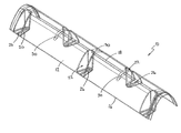
FIG. 2A shows a perspective view of the brisket barrier of FIG. 1;
FIG. 2B shows a perspective view of the brisket barrier of FIG. 2A, with hidden features being indicated by dashed lines;
FIGS. 2C to 2F show respectively top, side, bottom and cross sectional views of the brisket barrier of FIG. 2A;
FIG. 3 shows a side view of the interface between two interconnected brisket barriers;
FIG. 4 shows a perspective view of a second embodiment of a brisket barrier;
FIG. 5 shows how a plurality of brisket barriers may be stacked; and
FIGS. 6A and 6B show a plan and a side view respectively of a third embodiment of a brisket barrier.
DETAILED DESCRIPTION OF THE DRAWINGS
Referring now to FIGS. 1A and 1B of the drawings, there is shown, generally indicated as 40, an animal stall assembly including barriers 10 embodying the invention. The animal stall assembly 40 includes a plurality of animal stalls 11 (4 shown in FIG. 1B) such as may be used in, for example a cattle house or milking parlour. The barriers 10 are particularly suited for use in cow stalls (often referred to as cow cubicles) and may be referred to as brisket barriers. The brisket barrier 10 comprises a ridge shaped body 12 which, in use, is fixed to a ground surface 42 of the stall assembly 40, extending transversely across the respective stall 11 at or adjacent the front of the stall.
Referring now to FIGS. 2A to 2F, a preferred embodiment of the brisket barrier 10 is shown wherein the body 12 has a convex and curved cross section, which may for example be substantially parabolic in shape, providing a convex and curved, or rounded, external surface to the body 12. The body 12 is elongate and substantially linear in shape, and has first and second edges 16, 18, which, in use, rest upon the ground surface 42.
The barrier 10 may be releasably fixed to the surface 42 by means of screws, nails or other fixing device (not shown). To this end, the barrier 10 is provided with a plurality of recesses, formed in the body 12, each recess being adapted to receive at least one fixing. In preferred embodiments, the body 12 comprises at least one but typically a plurality of recessed sections 22. Each recessed section 22 is defined by a base portion, in the preferred form of a plate 20, which is preferably flat, and walls 24, 25. Advantageously, the base plate 20 is located substantially flush with the base of the body 12, or the plane in which the base of the body 12 lies, such that it contacts the ground surface 42 during use. In the illustrated embodiments, the base of the body 12 is defined by the edges 16, 18 and so the preferred arrangement is that the edges 16, 18 and the plates 20 are substantially coplanar.
The plates 20 preferably run substantially perpendicular with the longitudinal axis of the body 12. In the illustrated embodiments, each recessed section 22 extends from a respective edge 16, 18 towards the longitudinal axis of the body 12. Each recess 22 has opposing side walls 24, which typically extend substantially perpendicular with the respective plate 20, and an end wall 25 which extends between the side walls 24. The end walls 25 are preferably curved (convex with respect to the recess 22) in cross section. This is found to improve the rigidity of the barrier 10.
A fixing slot or aperture 26 is formed in each plate 20 through which a fixing device, for example as a nail, screw, bolt or the like, may, in use, be inserted to secure the body 12 to the ground surface 42. The slots 26 preferably run substantially perpendicular with the longitudinal axis of the body 12, advantageously along substantially the whole length of the plate 20. The arrangement is such that when fixings are in place in the slots 26, the barrier 10 can be moved in a direction perpendicular to the longitudinal axis of the body 12 with respect to the ground surface 42 and fixings. Such movement may be allowed or prevented, as desired, by appropriate loosening or tightening of the fixing means. In an alternative embodiment (not illustrated), a plurality of apertures or slots may be formed in the plate 20, spaced apart along its length, i.e. transversely of the ridge. In some embodiments (not illustrated), one or more slots or apertures may be provided which extend, or are spaced apart, in a direction parallel with the longitudinal axis of the body to allow the position of the barrier to be adjusted in the longitudinal direction.
In a preferred embodiment, the recessed sections 22 occur at intervals along the length of the body 12, preferably at substantially equal intervals along the body 12. In the illustrated embodiment, the recessed sections 22 are provided on each side of the body 12. Advantageously, the recesses 22 on one side of the body 12 are staggered, with respect to the recesses 22 on the other side, preferably with substantially uniform intervals between recesses 22. It is envisaged that this will result in less fixing being required and consequently the brisket barrier 10 being faster and easier to position.
The plates 20, and therefore the recesses 22, advantageously extend substantially to the longitudinal axis of the body 12, but preferably stop short of the longitudinal axis. This allows a relatively large amount of adjustability of the barrier 10, while still providing the body with a solid, or uninterrupted, apex portion 27 to help the rigidity of the body 12.
Advantageously, flanges 30 are provided on the internal surface of the body 12, for example extending from each end wall 25. Preferably, the flanges 30 extend at least partially across the apex of the body 12. The flanges 30 add strength to the barrier 10 and help to reduce its flexibility about its longitudinal axis.
The height of the barrier 10 is typically selected to be sufficiently high that an animal will be encouraged to lie with its body behind rather than on the barrier 10, but not so high that it is prevented from extending its legs over the barrier 10. By way of example, for use with cows in particular, the brisket barrier 10 may be approximately 130 mm in height. Conveniently, the brisket barrier 10 may be manufactured in lengths of approximately 600 mm to 1200 mm. The body 12 may be formed from any suitable material, especially rigid or semi-rigid plastics.
Referring to FIG. 3, a plurality of brisket barriers 10 may be positioned in an adjacent end-to-end manner to create a longer brisket barrier. In preferred embodiments, means for interconnecting adjacent brisket barriers 10 is provided. For example, the brisket barriers 10 shown in FIG. 2 have male connecting means in the preferred form of a flange 32 projecting from each end substantially parallel with the longitudinal axis. The flanges 32 may follow the cross sectional shape of the body 12 while being stepped inwardly of the external surface of the body 12.
A second embodiment of a brisket barrier shown in FIGS. 4A to 4F generally indicated as 110. The barrier 110 is similar to the barrier 10 and like numerals are used to indicate like parts. The barrier 110 does not, however, comprise the flanges 32. Instead, it includes respective female connecting means at each end which, in the present example, are adapted to receive the flanges 32. This may be achieved by making the body 12 open ended so that the flanges 32 of a barrier 10 may fit into a respective open end of a respective barrier 110. Preferably, the flanges 32 engage with the underside of the body 12 of the adjacent barrier 110 and this may conveniently be achieved by selecting the size of the step to be substantially equal to the thickness of the ends of the body 12.
It will be apparent that alternative embodiments of connecting means are possible and, in alternative embodiments, each barrier may have a male connector (e.g. flange 32) at one end of the body and a corresponding female connector (e.g. recess or open end) at the other end, for example in the form of a hybrid of the barriers 10, 110.
Referring to FIGS. 6A and 6B which show a third embodiment of a barrier 210, a flange 50 may be provided along one or both edges 16, 18 of the body 12. The, or each, flange 50 may extend partly or wholly along the length of the respective edge 16, 18, preferably lying in substantially the same plane as the base of the body 12 and/or the plates 20. The plates 20 may be integrally formed with the flanges 50. The flanges 50 add to the rigidity of the barrier 210. It will be seen that the barrier 210 is of the hybrid type referred to above. In this embodiment, the recesses 222 extend substantially to the longitudinal axis of the body 12. Preferably, an even number of recesses 222 is provided on each side of the barrier 210. This is in contrast to the barriers 10, 110 which have an odd number of recesses 22 on one side and an even number on the other side.
Referring to FIG. 5, the brisket barriers 10, 110, 210 may be stacked as shown such that the recessed sections 22 of a first brisket barrier 10 may receive the plates 20 of a second brisket barrier 10. As a result, brisket barriers 10 are easier to store when not in use.
In use, the brisket barriers 10, 110, 210 are positioned such that they run transversely across the ground surface 42 of the animal stall assembly 40 near the head of the stall 11 such that when an animal (not shown) steps into the stall 40 (which typically is a step up from a walkway) the animal moves forward towards the brisket barrier 10, 110, 210. The brisket barrier 10, 110, 210 is secured to the ground surface 42 of the stall by fixing means as described above. An operator (not shown) applies the fixings such that the brisket barrier 10 may move in the back and forth direction with respect to the ground surface 42 and fixings.
Where a plurality of stalls 11 are provided adjacent one another, a plurality of brisket barriers 10, 110, 210 may be laid adjacent one another, preferably interconnected as described above, such that the brisket barriers 10, 110, 210 run across all of the stalls 11.
When the animal lies down in the stall 11, the chest of the animal should be located near or adjacent the barrier 10, 110, 210. A typical purpose of the barrier 10, 110, 210 is to position the body of the animal such that the rear of the animal hangs off the rear of the stall 11 and that the head of the animal is not positioned too far forward in the stall 11. The animal may lie with one or both front legs extended over the brisket barrier 10, 110, 210. For this reason it is preferable that the brisket barrier is made of a relatively soft deformable, yet self-supporting, material. The convex shape of the brisket barrier 10, 110, 210 may also provide added rigidity. In addition, when some animals, e.g. cattle, stand up they naturally step forward in the stall 11. In this case the animal may step over and forwards of the brisket barrier 10, 110, 210 in the stall 11.
The present invention is not limited to the embodiment(s) described herein, which may be amended or modified without departing from the scope of the present invention.

Claims (19)

1. A brisket barrier for an animal stall, the barrier comprising a body shaped to define a ridge having an apex that is curved in transverse cross section, the body having at least one recessed section formed therein and extending into said ridge, said at least one recessed section including at least one slot formed therein extending in a direction transverse of the ridge and adapted to receive a fixing device, said at least one slot being adapted to receive said fixing device in a plurality of different locations, said locations being spaced apart in a direction transverse of the ridge, the brisket barrier being installable within an animal stall transverse to the orientation of the stall whereby an animal lying in the stall is able to extend its legs over the barrier.
2. A brisket barrier as claimed in claim 1, wherein said at least one recessed section includes a base portion in which said at least one slot is formed, said base portion being arranged to face, in use, a ground surface on which said barrier is mounted.
3. A brisket barrier as claimed in claim 2, wherein the body has a base for engagement with said ground surface, and said base portion of said at least one recessed section is substantially flush with said base of the body.
4. A brisket barrier as claimed in claim 1, wherein said at least one recessed section extends from an external surface of said ridge towards a notional plane that bisects the ridge longitudinally.
5. A brisket barrier as claimed in claim 4, wherein said at least one recessed section extends from said external surface substantially to said notional bisecting plane.
6. A brisket barrier as claimed in claim 4, wherein said ridge has a base and said at least one recessed section extends from the base of the ridge.
7. A brisket barrier as claimed in claim 1, wherein said at least one recessed section terminates in an end wall that is curved in transverse cross section.
8. A brisket barrier as claimed in claim 1, wherein at least one of said recessed sections is provided in each side of the ridge.
9. A brisket barrier as claimed in claim 8, wherein said at least one of said recessed sections provided in one side of the ridge are staggered with respect to said at least one of said recessed sections in the other side of the ridge in a longitudinal direction.
10. A brisket barrier as claimed in claim 1, wherein a plurality of said recessed sections are provided in each side of the ridge.
11. A brisket barrier as claimed in claim 1, wherein male or female connecting means are provided at each end of the body.
12. A brisket barrier as claimed in claim 1, wherein the ridge has a base, a respective flange being provided substantially at the base of the ridge along at least one side of the ridge, the respective flange extending longitudinally of the ridge.
13. An animal stall assembly comprising at least one animal stall having at least one brisket barrier as claimed in claim 1 located at an end of said at least one animal stall.
14. An animal stall assembly as claimed in claim 13, comprising a plurality of brisket barriers and wherein said brisket barriers are arranged in at least one row, adjacent barriers being longitudinally aligned and interconnected.
15. A brisket barrier as claimed in claim 1, wherein said body has a convex and curved substantially parabolic shape.
16. A brisket barrier for an animal stall, the barrier comprising:
a body shaped to define a ridge having an apex that is curved in transverse cross section, said body having a base for engagement with a ground surface and having at least one recessed section formed in said body with said at least one recessed section extending into said ridge from an external surface of said ridge towards a notional plane that bisects said ridge longitudinally;
said at least one recessed section including a base portion arranged to face, in use, a ground surface on which said barrier is mounted with said base portion of said at least one recessed section being substantially flush with said base of said body;
said base portion including at least one aperture formed therein extending in a direction transverse of said ridge and adapted to receive a fixing device, said at least one aperture being adapted to receive said fixing device in a plurality of different locations, said locations being spaced apart in a direction transverse of said ridge, said brisket barrier being installable within an animal stall transverse to the orientation of the stall whereby an animal lying in the stall is able to extend its legs over said brisket barrier.
17. A brisket barrier as claimed in claim 16, wherein said at least one recessed section extends from said external surface substantially to said notional bisecting plane.
18. A brisket barrier as claimed in claim 16, wherein at least one of said recessed sections is provided on either side of said ridge.
19. A brisket barrier as claimed in claim 18, wherein said at least one of said recessed sections provided in one side of said ridge are staggered with respect to said at least one of said recessed sections in the other side of said ridge in a longitudinal direction.
US11/859,025 2006-09-21 2007-09-21 Brisket barrier Expired - Fee Related US8074607B2 (en)

Applications Claiming Priority (2)

Application Number Priority Date Filing Date Title
GBGB0618587.0A GB0618587D0 (en) 2006-09-21 2006-09-21 A brisket barrier
GB0618587.0 2006-09-21

Publications (2)

Publication Number Publication Date
US20080072839A1 US20080072839A1 (en) 2008-03-27
US8074607B2 true US8074607B2 (en) 2011-12-13

Family

ID=37421360

Family Applications (1)

Application Number Title Priority Date Filing Date
US11/859,025 Expired - Fee Related US8074607B2 (en) 2006-09-21 2007-09-21 Brisket barrier

Country Status (4)

Country Link
US (1) US8074607B2 (en)
EP (1) EP1902614B1 (en)
CA (1) CA2603611A1 (en)
GB (1) GB0618587D0 (en)

Cited By (1)

* Cited by examiner, † Cited by third party
Publication number Priority date Publication date Assignee Title
US20130255587A1 (en) * 2012-04-02 2013-10-03 Schulte Corporation Migration Barriers, Systems and Methods

Families Citing this family (2)

* Cited by examiner, † Cited by third party
Publication number Priority date Publication date Assignee Title
WO2012164549A1 (en) * 2011-05-31 2012-12-06 Rodicon Limited An assembly and a method for forming a plurality of side by side animal stalls and a stall forming element and a method for forming the stall forming element
CN103392615B (en) * 2013-08-14 2015-04-08 中国农业大学 Bed for cows

Citations (7)

* Cited by examiner, † Cited by third party
Publication number Priority date Publication date Assignee Title
US3636829A (en) * 1969-12-24 1972-01-25 Sherwin Palmer Parking barrier
US5639179A (en) * 1995-08-24 1997-06-17 Jensen; Kevin M. Traffic safety control device
US5882140A (en) * 1997-01-30 1999-03-16 Yodock, Jr.; Leo J. Barrier device
USD421321S (en) 1997-04-17 2000-02-29 Promat Ltd. Animal support
USD520191S1 (en) * 2003-03-03 2006-05-02 Agriprom B.V. Animal brisket board
USD607611S1 (en) * 2007-09-05 2010-01-05 Delaval Holding Ab Brisket board
US7794103B2 (en) * 2007-08-16 2010-09-14 Hoover Scott C Parking space barrier block with photovoltaic illumination

Family Cites Families (4)

* Cited by examiner, † Cited by third party
Publication number Priority date Publication date Assignee Title
US5975026A (en) * 1998-01-08 1999-11-02 Merrill Equipment Company Free stall divider
NL1010497C2 (en) * 1998-08-13 2000-02-15 Boer Stalinrichtingen Cubicle partition.
US6467434B1 (en) * 1999-12-20 2002-10-22 Artex Fabricators Ltd. Cattle handling system and method of installing same
NL1025820C2 (en) * 2004-03-26 2005-09-27 Lely Entpr Ag Cubicle, cubicle construction with such a cubicle, partition part for use in such a cubicle and shed with such a cubicle or cubicle construction.

Patent Citations (7)

* Cited by examiner, † Cited by third party
Publication number Priority date Publication date Assignee Title
US3636829A (en) * 1969-12-24 1972-01-25 Sherwin Palmer Parking barrier
US5639179A (en) * 1995-08-24 1997-06-17 Jensen; Kevin M. Traffic safety control device
US5882140A (en) * 1997-01-30 1999-03-16 Yodock, Jr.; Leo J. Barrier device
USD421321S (en) 1997-04-17 2000-02-29 Promat Ltd. Animal support
USD520191S1 (en) * 2003-03-03 2006-05-02 Agriprom B.V. Animal brisket board
US7794103B2 (en) * 2007-08-16 2010-09-14 Hoover Scott C Parking space barrier block with photovoltaic illumination
USD607611S1 (en) * 2007-09-05 2010-01-05 Delaval Holding Ab Brisket board

Cited By (2)

* Cited by examiner, † Cited by third party
Publication number Priority date Publication date Assignee Title
US20130255587A1 (en) * 2012-04-02 2013-10-03 Schulte Corporation Migration Barriers, Systems and Methods
US9788531B2 (en) * 2012-04-02 2017-10-17 Organized Living Inc. Migration barriers, systems and methods

Also Published As

Publication number Publication date
EP1902614A1 (en) 2008-03-26
EP1902614B1 (en) 2012-11-14
GB0618587D0 (en) 2006-11-01
CA2603611A1 (en) 2008-03-21
US20080072839A1 (en) 2008-03-27

Similar Documents

Publication Publication Date Title
US20090165731A1 (en) Scratching and self-grooming tool
US8074607B2 (en) Brisket barrier
US20060107612A1 (en) Anchoring device
IES20070284A2 (en) A rubber tile
US7007632B1 (en) Milking parlor stall shoulder bumper
US8225749B2 (en) Cubicle, arrangement in a cubicle and a method for mounting said arrangement
US11910777B2 (en) Cubicles for bovine animals and accessories therefor
JPH08173006A (en) Bird injury prevention tool
US20180142496A1 (en) Fence Bracket
SE0000893D0 (en) A device for at least one milking stall and a parlor comprising a plurality of milking stalls
KR102155201B1 (en) Pet fence containing fall down prevention support
US20200146254A1 (en) Separating device for a livestock cubicle and arrangement thereof, in particular for a dairy farm
JPS5851739Y2 (en) Livestock shed
US20020096119A1 (en) Pet Chair
US11525474B1 (en) Fastener device for securing articles to a slatted floor
US11751532B2 (en) Pet enclosure
KR200331102Y1 (en) The floor construction of a delivery pigpen
CN214178544U (en) Combined dung leaking plate for breeding
KR200334577Y1 (en) Assembly fence for breeding pet
CN216982997U (en) Environment-friendly livestock fattening fence based on UPVC (unplasticized polyvinyl chloride) plates
JP3785286B2 (en) Boundary material for ground
RU2001123252A (en) HITCH
CN112021186A (en) Manure leaking floor convenient to assemble and disassemble
US20010048224A1 (en) Coupling for tubular elements arranged at right angles
JPS6025450Y2 (en) Mounting device for plate-shaped objects

Legal Events

Date Code Title Description
AS Assignment

Owner name: J WILSON AGRICULTURAL LTD, IRELAND

Free format text: ASSIGNMENT OF ASSIGNORS INTEREST;ASSIGNOR:CAMPBELL, BOB;REEL/FRAME:019859/0237

Effective date: 20070921

STCF Information on status: patent grant

Free format text: PATENTED CASE

FPAY Fee payment

Year of fee payment: 4

FEPP Fee payment procedure

Free format text: MAINTENANCE FEE REMINDER MAILED (ORIGINAL EVENT CODE: REM.); ENTITY STATUS OF PATENT OWNER: SMALL ENTITY

LAPS Lapse for failure to pay maintenance fees

Free format text: PATENT EXPIRED FOR FAILURE TO PAY MAINTENANCE FEES (ORIGINAL EVENT CODE: EXP.); ENTITY STATUS OF PATENT OWNER: SMALL ENTITY

STCH Information on status: patent discontinuation

Free format text: PATENT EXPIRED DUE TO NONPAYMENT OF MAINTENANCE FEES UNDER 37 CFR 1.362

FP Lapsed due to failure to pay maintenance fee

Effective date: 20191213